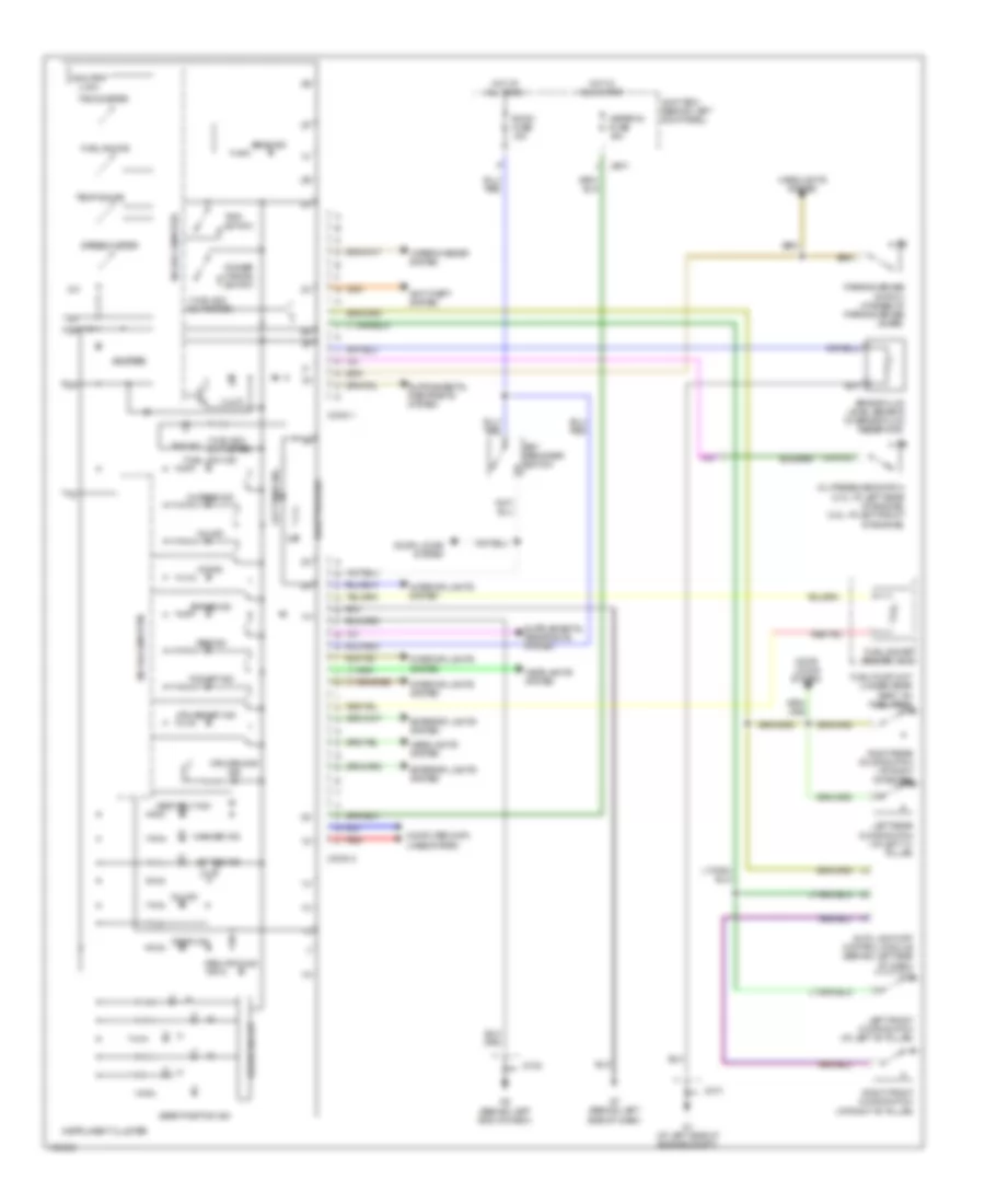
INSTRUMENT CLUSTER
Instrument Cluster Wiring Diagram for Mazda 6 i 2004
List of elements for Instrument Cluster Wiring Diagram for Mazda 6 i 2004:
- (w/ black out meter)
- A/t ind
- Abs ind
- Air bag ind
- Anti-theft system
- Auto light-off control module (behind left side of dash)
- Beam ind
- Brake fluid level sensor (in brake fluid reservoir)
- Brake ind
- Buzzer
- Charge ind
- Computer data lines system
- Conn 1
- Conn 2
- Cruise main ind
- Cruise set ind
- Dimmer cancel switch
- Door ind
- Door locks system
- Drive circuit
- Exterior lights system
- Fuel gauge
- Fuel gauge sender unit
- Fuel low ind
- Fuel pump unit (under rear seat, on fuel tank)
- G1 (at left side of engine compt)
- G2 (behind left end of dash)
- G7 (behind left side of dash)
- Gear position ind
- Headlights system
- Hot at all times
- Hot in run start
- Illum
- Instrument cluster
- Interior lights system
- Jb-01
- Jc-01
- Jc-02
- Joint box (behind left kick panel)
- Key reminder switch
- Left front door switch (at left "b" pillar)
- Left rear door switch (at left "c" pillar)
- Left turn ind
- Meter ig fuse 15a
- Microcomputer
- Mil ind
- Odo/trip (lcd)
- Oil ind
- Oil pressure switch (2.3l: at left rear of engine) (3.0l: at left front of engine)
- Parking brake switch (at base of parking brake lever)
- Red
- Right front door switch (at right "b" pillar)
- Right rear door switch (at right "c" pillar)
- Right turn ind
- Room fuse 15a
- Seat belt ind
- Security ind
- Speedometer
- Tachometer
- Tcs off ind
- Temp gauge
- Tns ind
- Trip switch
- Washer ind
- Wiper/washer system
 English