TRANSMISSION
2.3L
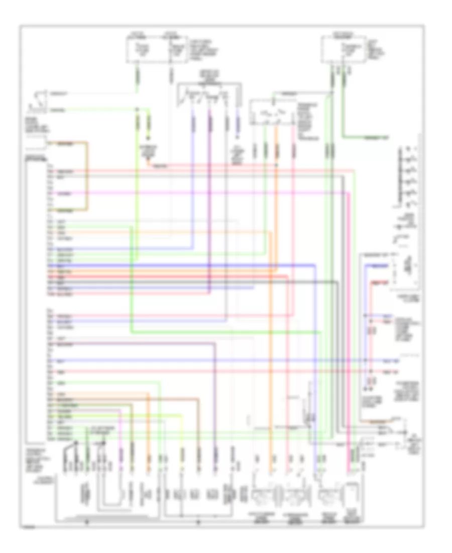
2.3L, A/T Wiring Diagram for Mazda 6 i 2004

List of elements for 2.3L, A/T Wiring Diagram for Mazda 6 i 2004:
- A/t ind
- At main relay
- Audio unit (w/o abs)
- Back fuse 5a
- Computer data lines system
- Control valve body
- Eng+b fuse 7.5a
- Exterior lights system
- G11 (under left front seat)
- G16 (at rear of engine)
- G2 (behind left end of dash)
- G2 (behind left side of dash)
- Gear position ind
- Hot at all times
- Hot in on
- Hot in on or start
- Input/turbine speed sensor (at left side of engine compartment)
- Instrument cluster
- J/c-02
- Jb-01
- Jb-02
- Joint box (behind left kick panel)
- Main fuse & relay box (on left front inner fender panel)
- Meter ig fuse 15a
- Microcomputer
- Oil pressure switch (at left rear of engine)
- Pressure control solenoid
- Range m
- Red
- Selector indicator circuit
- Selector lever component (sport a/t)
- Sensor temperature fluid transaxle
- Shift solenoid a
- Shift solenoid b
- Shift solenoid c
- Shift solenoid d
- Shift solenoid e
- Switch down
- Switch up
- Tcm fuse 10a
- Transaxle control module (tcm) (behind left side of dash)
- Transaxle range switch (at left side of engine compt, on transaxle)
- Vehicle speedometer sensor (at left rear of engine)
3.0L
3.0L, A/T Wiring Diagram for Mazda 6 i 2004
List of elements for 3.0L, A/T Wiring Diagram for Mazda 6 i 2004:
- (at left rear of engine)
- (at left side of engine compt, on transaxle)
- (behind left end of dash)
- (sport a/t) selector lever component
- 1aa
- 2-4 brake sol
- 2aa
- A/t ind
- Audio unit (m/t, w/o abs)
- Brake switch (under left side of dash)
- Computer data lines system
- Control sol pressure
- Control valve body
- Datalink connector 2 (under lower left side of dash)
- Down sw
- Eng+b fuse 7.5a
- Exterior lights system
- Fluid temp- erature sensor
- G11 (under left front seat)
- G17
- Gear position ind
- H2-03
- H2-04
- H2-05
- H2-06
- High clutch sol
- Hot at all times
- Hot in run or start
- Input/turbine speed sensor
- Instrument cluster
- Intermediate speed sensor
- J/c x-23
- J/c-02
- Jb-01
- Jb-02
- Joint box (behind left kick panel)
- M range
- Main fuse & relay box (on left front inner fender panel)
- Meter ig fuse 15a
- Micro- computer
- Nca
- Powertrain control module (pcm) (behind left side of dash)
- Red
- Reduction timing sol
- Selector indicator circuit
- Shift sol a
- Shift sol b
- Shift sol c
- Shift sol neutral
- Stop fuse 15a
- Tcc sol
- Transaxle control module (tcm) (behind left side of dash)
- Transaxle range switch
- Up sw
- Vehicle speed sensor
 English