COOLING FAN
Cooling Fan Wiring Diagram for Mercury Tracer GS 1997
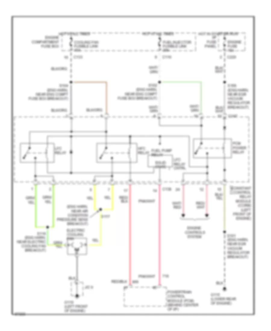
List of elements for Cooling Fan Wiring Diagram for Mercury Tracer GS 1997:
- (eng harn, near air condition pressure sens breakout)
- (left front of engine)
- C110
- C133
- C138
- C147
- C220
- Constant control relay module (ccrm)
- Controls system
- Cooling fan fusible link 40a
- Electric cooling fan
- Engine
- Engine fuse 15a
- Fuel injector fusible link 30a
- Fuel pump relay
- G110 (left front of engine)
- G115 (lower rear of engine)
- Hfc relay
- Hot at all times
- Hot at all times engine compartment fuse box
- Hot in start or run
- I/p fuse panel
- J/c 6
- Lfc relay
- Lfc relay cntrl
- Pcm power relay
- Powertrain control module (pcm) (behind center of i/p)
- S101 (eng harn, near egr vacuum regulator breakout)
- S102 (eng harn, near eng compt fuse box breakout)
- S104 (eng harn, near eng compt fuse box breakout)
- S116 (eng harn, near electric cooling fan breakout)
- S117
- Solid state
 English