SUPPLEMENTAL RESTRAINTS
Supplemental Restraint Wiring Diagram for Mercury Tracer GS 1997
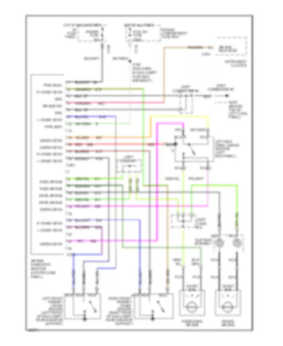
List of elements for Supplemental Restraint Wiring Diagram for Mercury Tracer GS 1997:
- Air bag diagnostic monitor (center dash panel)
- Air bag ind
- Air bag indicator
- C110
- C220
- C254
- C263
- C264
- Driver air bag
- Drvr air bag
- Engine compartment fuse box
- Engine fuse 15a
- Fuel inj fuse 30aa
- G200 (behind top of left cowl panel)
- Gnd
- Hot at all times
- Hot in run or start
- I/p fuse panel
- Instrument cluster
- Joint conn #11
- Joint conn #12
- Joint connector #3
- Joint connector #4
- L crash sens
- Left front primary crash sensor (left front of eng compt, near radiator support)
- Left kick panel safing sensor (left kick panel)
- Nca
- Pass air bag
- Passenger air bag
- Pwr (bat)
- Pwr (run)
- R crash sens
- Red
- Right front primary crash sensor (right front of eng compt, near radiator support)
- S102 (eng harn, in eng compt fuse box breakout)
- Safing sens
- Short bar
- Slip ring assembly
 English