GROUND DISTRIBUTION
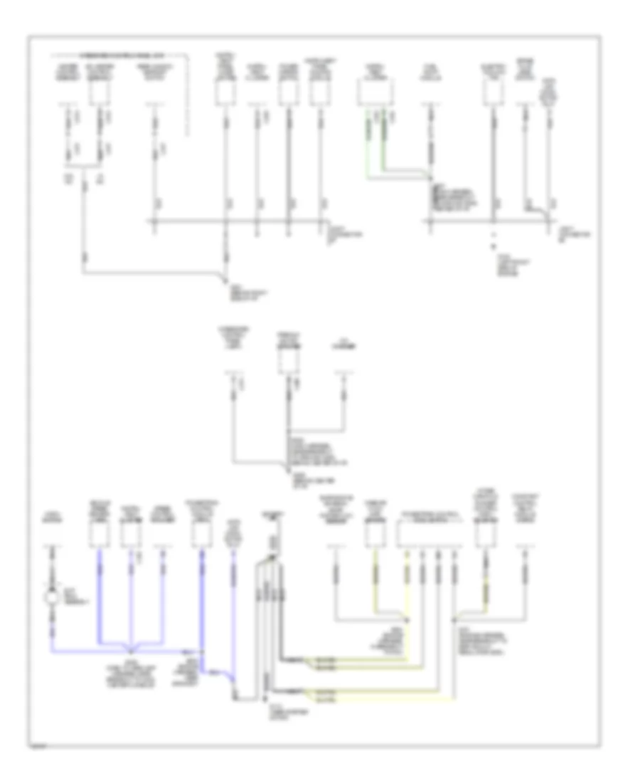
Ground Distribution Wiring Diagram (1 of 3) for Mercury Tracer GS 1997

List of elements for Ground Distribution Wiring Diagram (1 of 3) for Mercury Tracer GS 1997:
- (w/ power windows) one touch down control unit
- Abs control module
- Air bag diagnostic monitor
- Anti- theft hood switch
- Blower motor relay
- C230
- C246
- C247
- C249
- C251
- C263
- C295
- Daytime running lamps (drl) module
- Door lock/ unlock relay
- Ector #5, upper right kick panel)
- Electronic flasher
- Engine coolant level switch
- G101 (front of right fender apron)
- G106 (behind left headlamp)
- G120 (right front side of engine)
- G200 (behind top of left cowl panel)
- I/p fuse panel
- Joint conn- ector #1
- Joint connector #2
- Joint connector #3
- Joint connector #4
- Joint connector #5
- Left fog lamp
- Left front park/ turn lamp
- Left front side marker lamp
- Left headlamp
- Master window/ door lock switch
- Multi- function switch
- Multi-function switch
- Right fog lamp
- Right front park/ turn lamp
- Right front side marker lamp
- Right headlamp
- Right power window/ door lock switch
- S100 (dash to headlamp harness, near grommet)
- S200 (dash to headlamp harness, near breakout to joint connector #5, upper right kick panel)
- S203 (dash to headlamp harness, near grommet)
- S500 (driver's door harness, near breakout to left front door speaker)
- Warning chime module
- Wind- shield wiper motor
- Windshield washer pump motor
Ground Distribution Wiring Diagram (2 of 3) for Mercury Tracer GS 1997
List of elements for Ground Distribution Wiring Diagram (2 of 3) for Mercury Tracer GS 1997:
- A/c-heater control assembly
- Battery
- Brake fluid level switch
- C252
- C253
- C254
- C273
- C274
- C277
- C305
- Cd changer
- Constant control relay module (ccrm)
- Data link conn- ector (dlc)
- Electric cooling fan
- Evaporative emission (evap) purge flow sensor
- Fuel pump module
- G100 (left front side of engine)
- G112 (near starter motor)
- G201 (behind right side of i/p)
- G206 (behind center of i/p)
- Heater control assembly
- Horn switch
- Instru- ment cluster
- Instru- ment panel cigar lighter
- Instrument panel dimming module
- Intake manifold runner control (imrc) solenoid
- Integrated control panel (icp)
- Joint connector #6
- Joint connector #7
- Mass air flow (maf) sensor
- Nca
- Power mirror switch
- Powertrain control module (pcm)
- Premium sound amplifier
- Rear window defrost switch
- S101 (engine harness, near breakout to egr vacuum regulator (evr))
- S204 (engine harness, in breakout to pcm)
- S205 (engine harness, near grommet)
- S206 (dash to headlamp harness, near breakout to c202, center console)
- S207 (main harness, near breakout to ground g206, center of i/p)
- S208 (main harness, near breakout to ground c206, behind center of i/p)
- Slip ring assembly
- Speed control amplifier
- Vehicle speed sensor (vss)
- W/ a/c
- W/o a/c
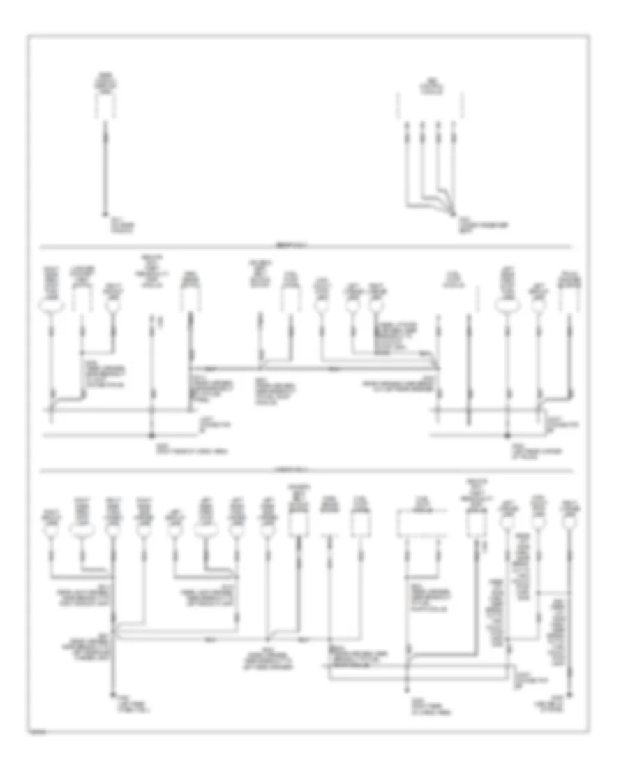
Ground Distribution Wiring Diagram (3 of 3) for Mercury Tracer GS 1997
List of elements for Ground Distribution Wiring Diagram (3 of 3) for Mercury Tracer GS 1997:
- (rear lift- gate harn, near break- out to high mount stop lamp) s405
- (rear liftgate harness, near breakout to hi-mount stop lamp) s405
- Abs control module
- C404
- Driver's seat belt buckle switch
- Fuel pump diode
- Fuel pump module
- G301 (under passenger seat)
- G402 (left rear wheel well)
- G404 (left rear corner of trunk)
- G405 (right rear of cargo area)
- G406 (center of liftgate)
- G411 (on rear window)
- High mount stop lamp
- Joint connector #8
- Joint connector #9
- Left backup lamp
- Left license lamp
- Left rear park/ stop lamp
- Left rear park/ stop/ turn lamp
- Left rear side marker lamp
- Left rear turn/ hazard lamp
- Luggage compart- ment switch
- Nca
- Park sense switch
- Rear window defrost grid
- Remote anti- theft personality (rap) module
- Right backup lamp
- Right license lamp
- Right rear park/ stop lamp
- Right rear park/ stop/ turn lamp
- Right rear side marker lamp
- Right rear turn/ hazard lamp
- S314 (rear harness, near breakout to i/p fuse panel)
- S401 (rear harness, near breakout to left rear side marker lamp)
- S402 (rear harness, near break- out left rear speaker)
- S402 (rear harness, near breakout to left rear speaker)
- S403 (rear harness, near breakout to fuel pump module)
- S404 (rear harness, near breakout to fuel pump module)
- S407 (rear lift- gate harn, near break- out to high mount stop lamp)
- S408 (rear harness, near breakout to joint connector #8)
- S414 (rear lamp harness, near breakout to right backup lamp)
- S415 (rear lamp harness, near breakout to left backup lamp)
- Sedan only
- Trunk release solenoid
- Wagon only