AIR CONDITIONING
4.0L
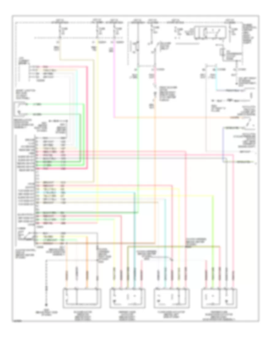
4.0L, Manual A/C Wiring Diagram (1 of 2) for Ford Mustang 2006
 https://portal-diagnostov.com/license.html
Automotive Electricians Portal FZCO
Automotive Electricians Portal FZCO
https://portal-diagnostov.com/license.html
https://portal-diagnostov.com/license.html
Automotive Electricians Portal FZCO
Automotive Electricians Portal FZCO
List of elements for 4.0L, Manual A/C Wiring Diagram (1 of 2) for Ford Mustang 2006:
- (at rear of engine) s100
- (behind center of dash)
- (in main harness, behind center of dash) s203
- (in main harness, behind center of dash) s202
- (in main harness, behind right side of dash) s200
- (on left front of engine compartment) g101
- (right front of engine compt)
- A/c clutch cycling pressure switch (left rear corner of engine compt)
- A/c clutch field coil (lower left side of engine)
- A/c clutch relay
- A/c compressor clutch diode
- A/c demand
- Blend dr act
- Blower motor relay
- Blower motor resistor (behind right side of dash)
- Blwr mtr rly
- Bussed electrical center (bec)
- C1035a c1
- C1035b b6
- C1035c f5
- C2280a
- C2280b
- C2280h
- C294a
- C294b
- Climate control module (behind center of dash)
- Def mode act
- Defrost mode actuator (behind right side of dash)
- Floor mode actuator (behind left side of dash)
- Flr mode act
- Front blower motor (behind right side of dash, in a/c heater plenum)
- Fuse 15a
- Fuse 30a
- Fuse 5a
- G200 (behind right side of dash)
- G201 (behind right side of dash)
- G203 (at right "a" pillar)
- Ground
- High
- Hot at all times
- Hot in acc or run
- Hot in start or run
- Illum
- Low
- Low current board
- Pnk
- Rear def ind
- Rear def sw
- Recirc dr mtr
- Recirculation door motor (on evaporator assembly)
- S201
- S211 (behind dash, on evaporator assembly)
- Sig rtn
- Smart junction box (sjb) (at right kick panel)
- Temperature blend door actuator (behind dash, on evaporator assembly)
- Vpwr
- Vref
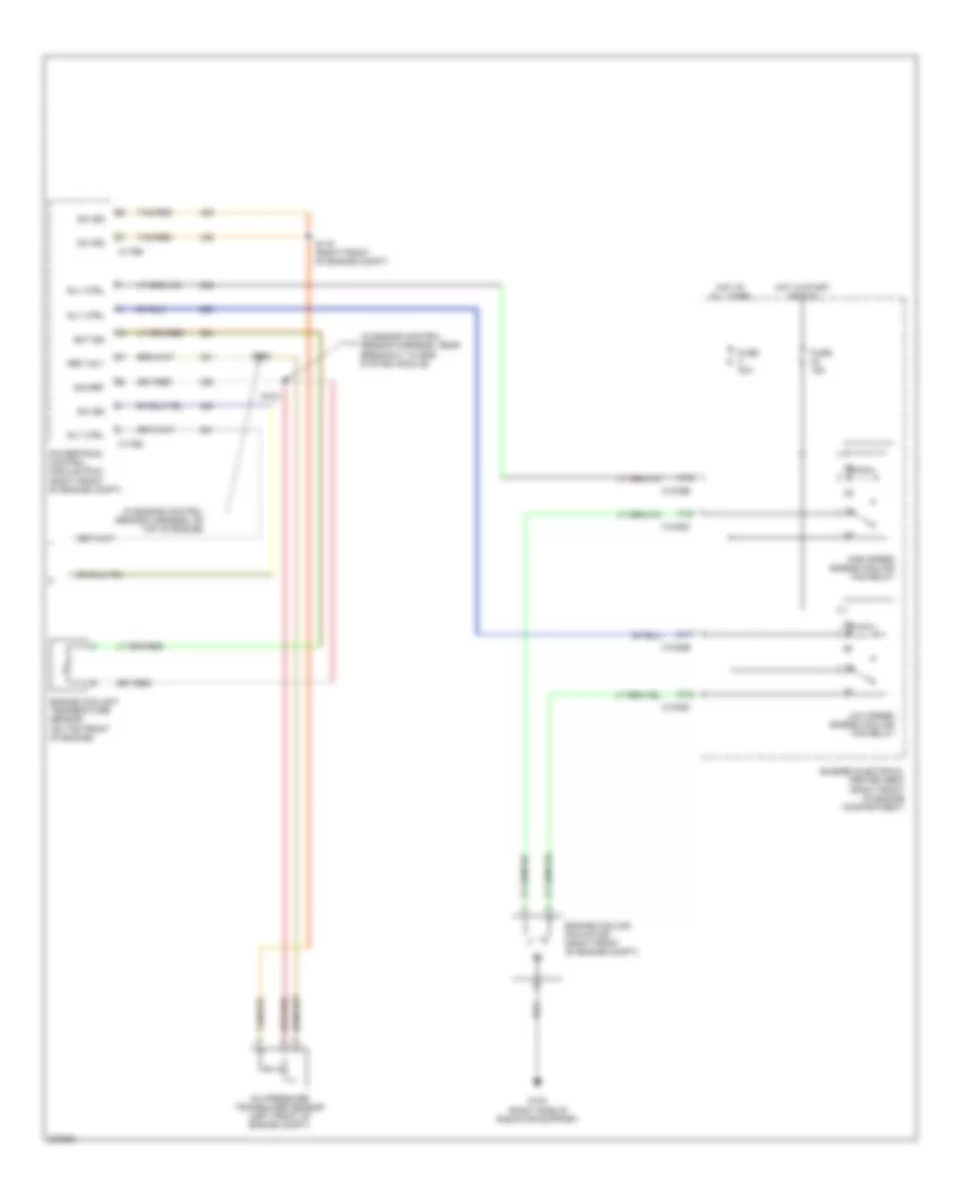
4.0L, Manual A/C Wiring Diagram (2 of 2) for Ford Mustang 2006
List of elements for 4.0L, Manual A/C Wiring Diagram (2 of 2) for Ford Mustang 2006:
- (in engine control sensor harness, near breakout to egr system module)
- (in engine control sensor harness, on top of engine)
- A/c pressure transducer sensor (left front of engine compt)
- A12
- Bussed electrical center (bec) (right front of engine compartment)
- C1035b
- C1035c
- C11
- C12
- C175b
- C175e
- Ect sig
- Engine coolant temperature sensor (on top front of engine)
- Engine cooling fan motor (right front of engine compt)
- F12
- Fuse 15a
- Fuse 40a
- G100 (right side of radiator support)
- High speed engine cooling fan relay
- Hot at all times
- Hot in start or run
- Low speed engine cooling fan relay
- Powertrain control module (pcm) (right front of engine compt)
- Ref volt
- Rly ctrl
- S102
- S103
- S116 (right front of engine compt)
- Sig ret
- Sw sig
- Tan/red
4.6L
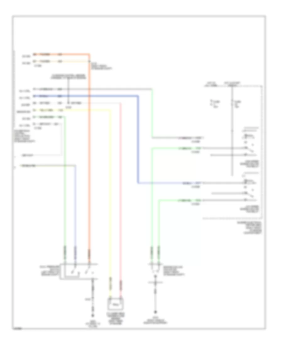
4.6L, Manual A/C Wiring Diagram (1 of 2) for Ford Mustang 2006
List of elements for 4.6L, Manual A/C Wiring Diagram (1 of 2) for Ford Mustang 2006:
- (behind center of dash)
- (in main harness, behind center of dash) s203
- (in main harness, behind center of dash) s202
- (in main harness, behind right side of dash) s200
- (on left front of engine compartment) g101
- (right front of engine compt)
- A/c clutch cycling pressure switch (left rear corner of engine compt)
- A/c clutch field coil (lower left side of engine)
- A/c clutch relay
- A/c compressor clutch diode
- A/c demand
- Blend dr act
- Blower motor relay
- Blower motor resistor (behind right side of dash)
- Blwr mtr rly
- Bussed electrical center (bec)
- C1035a c1
- C1035b b6
- C1035c f5
- C2280a
- C2280b
- C2280h
- C294a
- C294b
- Climate control module (behind center of dash)
- Def mode act
- Defrost mode actuator (behind right side of dash)
- Floor mode actuator (behind left side of dash)
- Flr mode act
- Front blower motor (behind right side of dash, in a/c heater plenum)
- Fuse 15a
- Fuse 30a
- Fuse 5a
- G200 (behind right side of dash)
- G201 (behind right side of dash)
- G203 (at right "a" pillar)
- Ground
- High
- Hot at all times
- Hot in acc or run
- Hot in start or run
- Illum
- Low
- Low current board
- Pnk
- Rear def ind
- Rear def sw
- Recirc dr mtr
- Recirculation door motor (on evaporator assembly)
- S100
- S201
- S211 (behind dash, on evaporator assembly)
- Sig rtn
- Smart junction box (sjb) (at right kick panel)
- Temperature blend door actuator (behind dash, on evaporator assembly)
- Vpwr
- Vref
4.6L, Manual A/C Wiring Diagram (2 of 2) for Ford Mustang 2006
List of elements for 4.6L, Manual A/C Wiring Diagram (2 of 2) for Ford Mustang 2006:
- (in engine control sensor harness, at rear of engine)
- A12
- Bussed electrical center (bec) (right front of engine compartment)
- C1035b
- C1035c
- C11
- C12
- C175b
- C175e
- Cylinder head temperature sensor (right rear of engine)
- Dual pressure switch (left front of engine compt)
- Engine cooling fan motor (right front of engine compt)
- F12
- Fuse 15a
- Fuse 40a
- G100 (right side of radiator support)
- G203 (at right "a" pillar)
- High speed engine cooling fan relay
- Hot at all times
- Hot in start or run
- Low speed engine cooling fan relay
- Powertrain control module (pcm) (right front of engine compt)
- Rly ctrl
- S100
- S106
- S116 (right front of engine compt)
- Sensor sig
- Sig ret
- Sw sig
- Tan/red

 Dansk
Dansk Deutsch
 Ελληνικά
 English
 English
 Español
 Suomi
Suomi Français
 Français
 עברית
עברית Hrvatski
 Magyar
 Italiano
 日本語
日本語 한국어
한국어 Nederlands
 Polski
 Português
 Português
 Română
 Русский
 Slovenčina
 Slovenščina
 Svenska
 Türkçe
 中文 (中国)