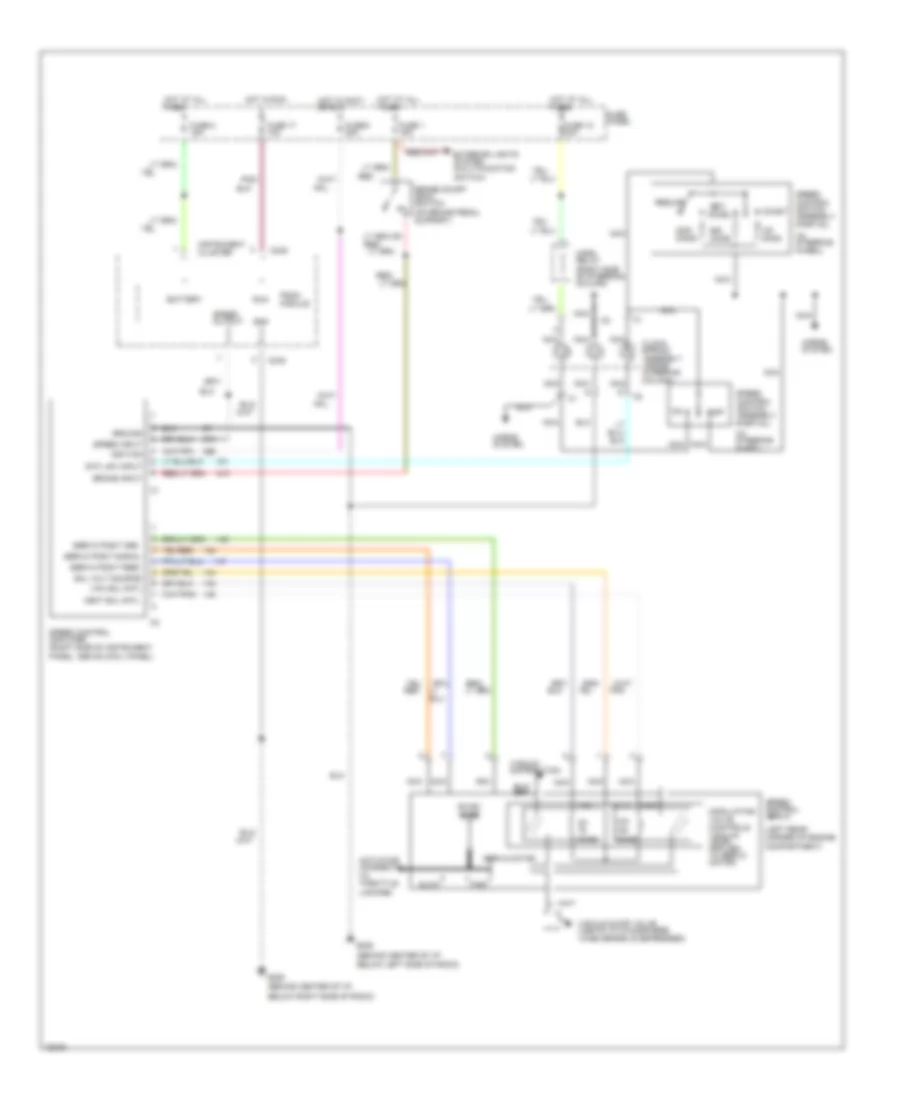
CRUISE CONTROL
Cruise Control Wiring Diagram for Ford Aerostar 1995
List of elements for Cruise Control Wiring Diagram for Ford Aerostar 1995:
- (behind center of i/p,
- (in steering wheel)
- (left rear corner of engine compartment)
- (on brake pedal support)
- 100-
- 40-
- 50,000 ohms
- Accel
- Actuator (connects to throttle linkage)
- Battery
- Below left side of radio)
- Below right side of radio)
- Brake input
- Brake on/off (boo) switch
- C249
- Clock- spring assembly (inside steering column)
- Cntl sw input
- Coast
- Exterior lights system (multi-function switch)
- Fast
- Fuse 1 15a
- Fuse 12 30a
- Fuse 17 10a
- Fuse 6 20a
- Fuse 8 15a
- Fuse panel
- G206
- Gnd
- Ground
- Horn relay (right side of steering column)
- Horns system
- Horns system
- Hot at all times
- Hot in accy or run
- Hot in run
- Ignition
- Instrument cluster
- Nca
- Off
- Ohms
- Pnk
- Pnk/
- Psom module
- Red
- Red/
- Resume
- Run
- Servo motor
- Servo posit feed
- Servo posit gnd
- Servo posit signal
- Set/
- Slow
- Sol volt source
- Sol+
- Speed output
- Speed control amplifier (right side of instrument panel, above cowl panel)
- Speed control servo
- Speed control switch assembly (partial)
- Speed input
- Vac
- Vac sol cntl
- Vacuum distribution
- Vacuum dump valve (vents to atmosphere when brake is depressed)
- Vent
- Vent sol cntl
 Dansk
Dansk Deutsch
 Ελληνικά
 English
 English
 Español
 Suomi
Suomi Français
 Français
 עברית
עברית Hrvatski
 Magyar
 Italiano
 日本語
日本語 한국어
한국어 Nederlands
 Polski
 Português
 Português
 Română
 Русский
 Slovenčina
 Slovenščina
 Svenska
 Türkçe
 中文 (中国)
 Čeština