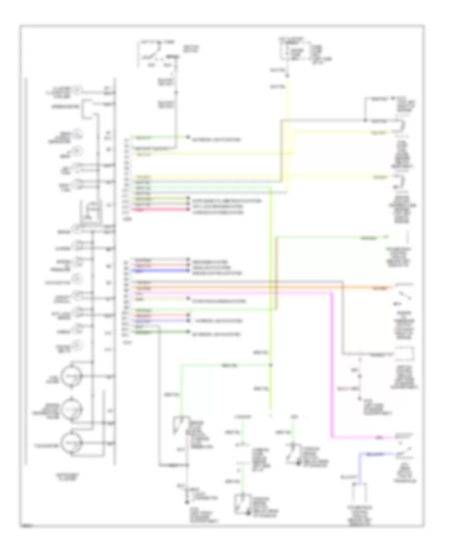
INSTRUMENT CLUSTER
Instrument Cluster Wiring Diagram for Ford Aspire SE 1994
List of elements for Instrument Cluster Wiring Diagram for Ford Aspire SE 1994:
- 5th gear switch (top of transaxle)
- A10
- A11
- A12
- A13
- A14
- Acc
- Airbag
- Anti-lock brake
- Anti-lock brakes system
- B10
- B11
- B12
- B13
- B14
- Brake
- Brake fluid level switch (in brake fluid reservoir)
- C109
- C209
- C210
- Canada
- Charge
- Cluster illumination (4 bulbs)
- Dash fuse box (left side of i/p)
- Defogger system
- Engine controls system
- Engine coolant temperature gauge
- Engine coolant temperature sender (top left side of engine)
- Engine oil pressure
- Engine oil pressure switch (top right front of engine)
- Exterior lights system
- Fasten belts
- Fuel gauge
- Fuel pump/ fuel gauge sender (below rear seat)
- G100 (left front of engine compartment)
- G102 (left side of engine compartment)
- G110 (top left front of engine)
- Headlights system
- Hi beam
- Hot at all times
- Hot in start or run
- Ignition control module (left side of engine compartment)
- Ignition switch
- Instrument cluster
- Interior lights system
- Joint connector
- Left turn
- Lock
- Malfunction
- Meter fuse 15a
- Parking brake switch (below rear of console)
- Pnk
- Powertrain control module (behind left side of i/p)
- Rear window defroster
- Right turn
- Run
- Speedometer
- Start
- Starting/charging system
- Tachometer
- Upshift (manual)
- Usa
- Warning chime module (behind left side of i/p)
- Warning systems system
 Dansk
Dansk Deutsch
 Ελληνικά
 English
 English
 Español
 Suomi
Suomi Français
 Français
 עברית
עברית Hrvatski
 Magyar
 Italiano
 日本語
日本語 한국어
한국어 Nederlands
 Polski
 Português
 Português
 Română
 Русский
 Slovenčina
 Slovenščina
 Svenska
 Türkçe
 中文 (中国)
 Čeština