TRANSMISSION
4.2L
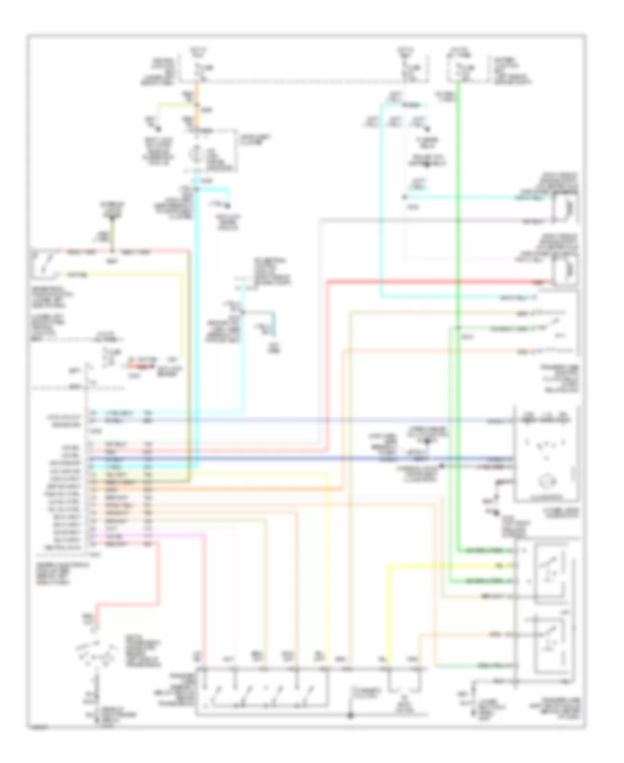
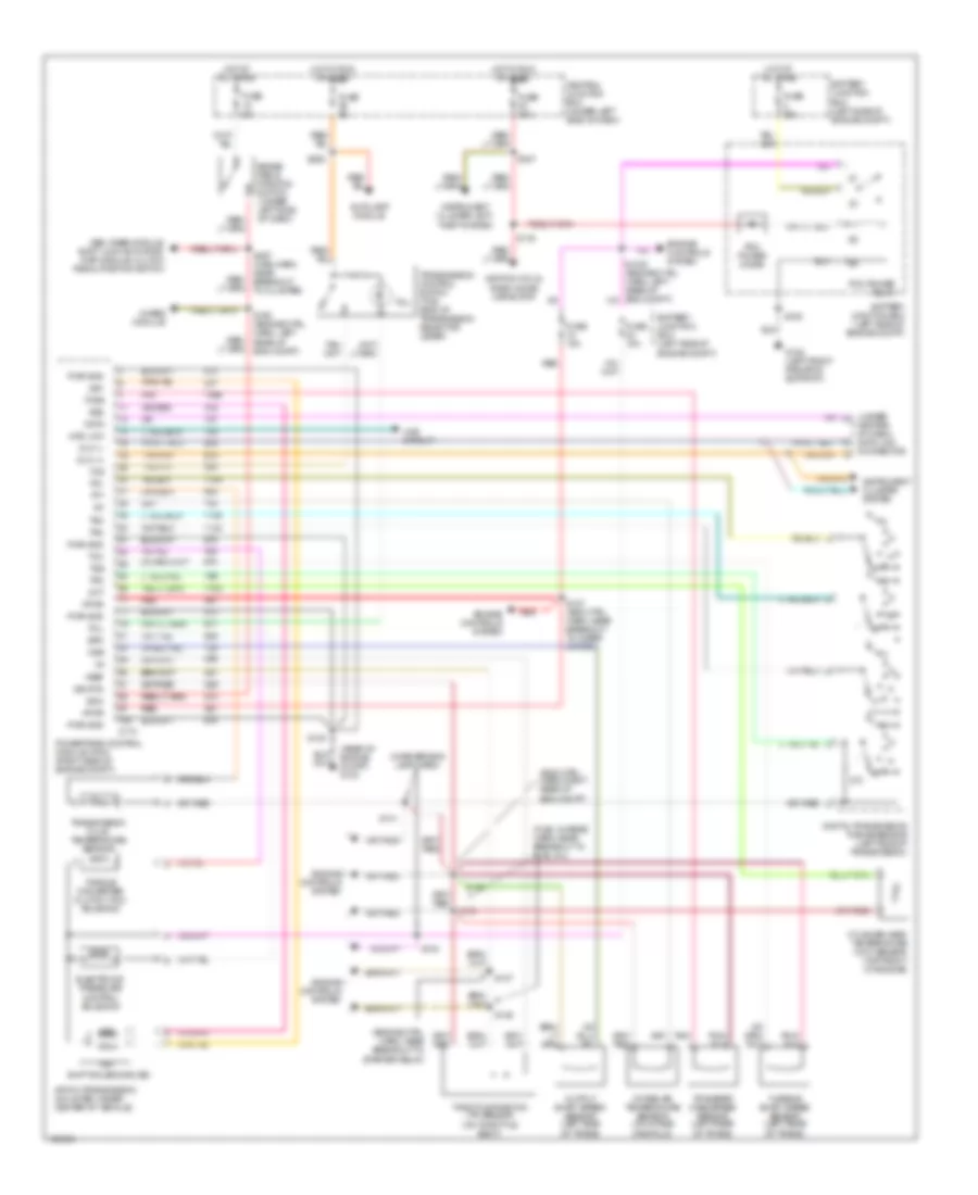
4.2L, A/T Wiring Diagram, 4R70W for Ford Pickup F250 Super Duty 1999
 https://portal-diagnostov.com/license.html
Automotive Electricians Portal FZCO
Automotive Electricians Portal FZCO
https://portal-diagnostov.com/license.html
https://portal-diagnostov.com/license.html
Automotive Electricians Portal FZCO
Automotive Electricians Portal FZCO
List of elements for 4.2L, A/T Wiring Diagram, 4R70W for Ford Pickup F250 Super Duty 1999:
- (engine ctrl harn, near breakout to starter relay)
- (engine ctrl harn, right rear of engine compt)
- (fuel charge harn, near breakout to fuel inj)
- (in reversing lamp harn)
- (rear of engine compartment) g123
- (under center of dash) data link connector
- 4r70w transmission (mounted under center of vehicle)
- 4wabs module
- 4wd circuit
- 4wd low
- Autolamp module
- Battery junction box (left side of engine compt)
- Boo
- Brake pedal position switch (under left side of dash)
- C174
- Central junction box (under left side of dash)
- Cht
- Cylinder head temperature (cht) sensor (4.2l: left side of engine) (4.6l: top front of engine)
- Data
- Digital transmission range sensor (left side of transmission)
- Dlc (+)
- Dlc (-)
- Electronic pressure control solenoid
- Engine controls system
- Epc
- Fuse 15a
- Fuse 30a
- Fuse 5a
- G108 (left front radiator support)
- Gem, rabs module, shift lock actuator, rap module, clutch pedal position switch
- Hot at all times
- Hot in run or start
- Iat
- Ignition coils, radio noise capacitor
- Instrument cluster system
- Instrument cluster, anti- theft system
- Intake air temperature sensor (on intake manifold)
- Oss
- Output shaft speed sensor (left side of trans)
- Pcm power diode
- Pcm power relay
- Pnk
- Powertrain control module (pcm) (right side of engine compt)
- Pwr gnd
- R p
- Red
- S100
- S106
- S116
- S127 (eng ctrl harn, near breakout to wiper motor)
- S135
- S136
- S137
- S138
- S140
- S141
- S160 (engine ctrl harn, left rear of eng compt)
- S225
- S237
- S297 (main harn, near breakout to cluster)
- Shift solenoids (ss)
- Sig rtn
- Ss1
- Ss2
- Tcc
- Tcil
- Tcs
- Tcss
- Tft
- Throttle position (tp) sensor (on throttle body)
- Torque converter clutch (tcc) solenoid
- Tr1
- Tr2
- Tr3
- Tr4
- Transfer case speed sensor (left rear of trans)
- Transmission control switch (tcs) (end of transmission selector lever)
- Transmission fluid temperature sensor
- Vpwr
- Vref
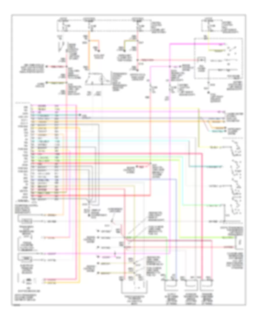
4WD Wiring Diagram, Electronic for Ford Pickup F250 Super Duty 1999
List of elements for 4WD Wiring Diagram, Electronic for Ford Pickup F250 Super Duty 1999:
- (lower right kick panel) g203
- (main harn, near breakout to gem)
- (right side of engine compt) 4x2 center axle disconnect solenoid
- (right side of engine compt) 4x4 center axle disconnect solenoid
- (under left side of dash) central junction box
- 1.1k ohms
- 3.9k ohms
- 4 wheel drive mode switch
- 4wd low out
- 4wd output
- 4x2 sol
- 4x4 high ind
- 4x4 high range indicator
- 4x4 mode sw
- 4x4 sol
- Anti-lock brake module
- Anti-lock brakes
- Apron) g105
- Batt
- Battery junction box (left side of engine compt)
- Bpp sw input
- Brake pedal position switch (under left side of dash)
- C174
- C236
- C239
- C241
- C243
- Central junction box (under left side of dash)
- Digital transmission range (dtr) sensor (left side of transmission)
- Exterior lights system
- Flasher relay
- Fuse 10a
- Fuse 30a
- Fuse 5a
- G108 (top front radiator support)
- Generic electronic module (gem) (behind left side of dash)
- H2l
- H2l rly ctrl
- Hot at all times
- Hot in run
- Illumination
- Instrument cluster
- Interior lights (instrument illumination)
- L2h
- L2h rly ctrl
- Magnetic clutch
- Neutral sw in
- Not used
- Ohms
- Powertrain control module (right side of engine compt)
- Red
- S102
- S120
- S142 (engine ctrl harn, near breakout to pwr dist box)
- S201
- S202
- S213
- S228
- S232 (main harn, near breakout to instrument cluster)
- S238
- S265
- S297
- Shift lock actuator, rear air suspension module
- Shift motor
- Sig return
- Sw a input
- Sw b input
- Sw c input
- Sw d input
- Tcec rly ctrl
- Trailer tow battery relay
- Transfer case assembly (below vehicle, behind transmission)
- Transfer case electric clutch relay (in rpo relay block)
- Transfer case shift relay module (behind center of dash)
- Wiper/washer (multi-function switch)
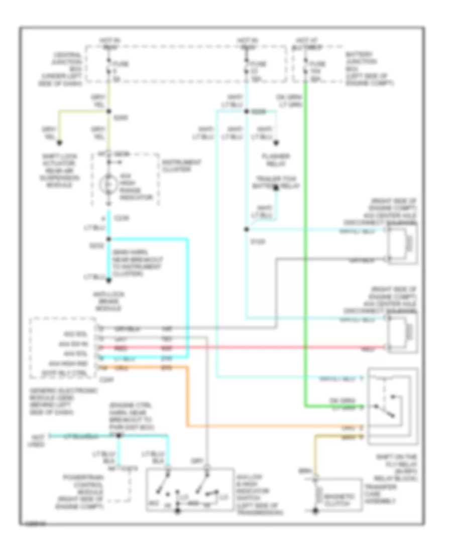
4WD Wiring Diagram, Mechanical for Ford Pickup F250 Super Duty 1999
List of elements for 4WD Wiring Diagram, Mechanical for Ford Pickup F250 Super Duty 1999:
- (engine ctrl harn, near breakout to pwr dist box) s142
- (main harn, near breakout to instrument cluster)
- (right side of engine compt) 4x2 center axle disconnect solenoid
- (right side of engine compt) 4x4 center axle disconnect solenoid
- 4x2
- 4x2 sol
- 4x4 high ind
- 4x4 high range indicator
- 4x4 low & high indicator switch (left side of transmission)
- 4x4 sol
- 4x4 sw in
- Anti-lock brake module
- Battery junction box (left side of engine compt)
- C174
- C236
- C241
- Central junction box (under left side of dash)
- Flasher relay
- Fuse 10a
- Fuse 30a
- Fuse 5a
- Generic electronic module (gem) (behind left side of dash)
- Hot at all times
- Hot in run
- Instrument cluster
- Magnetic clutch
- Not used
- Powertrain control module (right side of engine compt)
- Red
- S120
- S228
- S232
- S265
- Shift lock actuator, rear air suspension module
- Shift on the fly relay (in rpo relay block)
- Sotf rly ctrl
- Trailer tow battery relay
- Transfer case assembly
4.6L
4.6L, A/T Wiring Diagram, 4R70W for Ford Pickup F250 Super Duty 1999
List of elements for 4.6L, A/T Wiring Diagram, 4R70W for Ford Pickup F250 Super Duty 1999:
- (engine ctrl harn, near breakout to starter relay)
- (engine ctrl harn, right rear of engine compt)
- (fuel charge harn, near breakout to fuel inj)
- (in reversing lamp harn)
- (rear of engine compartment) g123
- (under center of dash) data link connector
- 4r70w transmission (mounted under center of vehicle)
- 4wabs module
- 4wd circuit
- 4wd low
- Autolamp module
- Battery junction box (left side of engine compt)
- Boo
- Brake pedal position switch (under left side of dash)
- C174
- Central junction box (under left side of dash)
- Cht
- Cylinder head temperature (cht) sensor (4.2l: left side of engine) (4.6l: top front of engine)
- Data
- Digital transmission range sensor (left side of transmission)
- Dlc (+)
- Dlc (-)
- Electronic pressure control solenoid
- Engine controls system
- Epc
- Fuse 15a
- Fuse 30a
- Fuse 5a
- G108 (left front radiator support)
- Gem, rabs module, shift lock actuator, rap module, clutch pedal position switch
- Hot at all times
- Hot in run or start
- Iat
- Ignition coils, radio noise capacitor
- Instrument cluster system
- Instrument cluster, anti- theft system
- Intake air temperature sensor (on intake manifold)
- Oss
- Output shaft speed sensor (left side of trans)
- Pcm power diode
- Pcm power relay
- Pnk
- Powertrain control module (pcm) (right side of engine compt)
- Pwr gnd
- R p
- Red
- S100
- S106
- S116
- S127 (eng ctrl harn, near breakout to wiper motor)
- S135
- S136
- S137
- S138
- S140
- S141
- S160 (engine ctrl harn, left rear of eng compt)
- S225
- S237
- S297 (main harn, near breakout to cluster)
- Shift solenoids (ss)
- Sig rtn
- Ss1
- Ss2
- Tcc
- Tcil
- Tcs
- Tcss
- Tft
- Throttle position (tp) sensor (on throttle body)
- Torque converter clutch (tcc) solenoid
- Tr1
- Tr2
- Tr3
- Tr4
- Transfer case speed sensor (left rear of trans)
- Transmission control switch (tcs) (end of transmission selector lever)
- Transmission fluid temperature sensor
- Vpwr
- Vref
4WD Wiring Diagram, Electronic for Ford Pickup F250 Super Duty 1999
List of elements for 4WD Wiring Diagram, Electronic for Ford Pickup F250 Super Duty 1999:
- (lower right kick panel) g203
- (main harn, near breakout to gem)
- (right side of engine compt) 4x2 center axle disconnect solenoid
- (right side of engine compt) 4x4 center axle disconnect solenoid
- (under left side of dash) central junction box
- 1.1k ohms
- 3.9k ohms
- 4 wheel drive mode switch
- 4wd low out
- 4wd output
- 4x2 sol
- 4x4 high ind
- 4x4 high range indicator
- 4x4 mode sw
- 4x4 sol
- Anti-lock brake module
- Anti-lock brakes
- Apron) g105
- Batt
- Battery junction box (left side of engine compt)
- Bpp sw input
- Brake pedal position switch (under left side of dash)
- C174
- C236
- C239
- C241
- C243
- Central junction box (under left side of dash)
- Digital transmission range (dtr) sensor (left side of transmission)
- Exterior lights system
- Flasher relay
- Fuse 10a
- Fuse 30a
- Fuse 5a
- G108 (top front radiator support)
- Generic electronic module (gem) (behind left side of dash)
- H2l
- H2l rly ctrl
- Hot at all times
- Hot in run
- Illumination
- Instrument cluster
- Interior lights (instrument illumination)
- L2h
- L2h rly ctrl
- Magnetic clutch
- Neutral sw in
- Not used
- Ohms
- Powertrain control module (right side of engine compt)
- Red
- S102
- S120
- S142 (engine ctrl harn, near breakout to pwr dist box)
- S201
- S202
- S213
- S228
- S232 (main harn, near breakout to instrument cluster)
- S238
- S265
- S297
- Shift lock actuator, rear air suspension module
- Shift motor
- Sig return
- Sw a input
- Sw b input
- Sw c input
- Sw d input
- Tcec rly ctrl
- Trailer tow battery relay
- Transfer case assembly (below vehicle, behind transmission)
- Transfer case electric clutch relay (in rpo relay block)
- Transfer case shift relay module (behind center of dash)
- Wiper/washer (multi-function switch)
4WD Wiring Diagram, Mechanical for Ford Pickup F250 Super Duty 1999
List of elements for 4WD Wiring Diagram, Mechanical for Ford Pickup F250 Super Duty 1999:
- (engine ctrl harn, near breakout to pwr dist box) s142
- (main harn, near breakout to instrument cluster)
- (right side of engine compt) 4x2 center axle disconnect solenoid
- (right side of engine compt) 4x4 center axle disconnect solenoid
- 4x2
- 4x2 sol
- 4x4 high ind
- 4x4 high range indicator
- 4x4 low & high indicator switch (left side of transmission)
- 4x4 sol
- 4x4 sw in
- Anti-lock brake module
- Battery junction box (left side of engine compt)
- C174
- C236
- C241
- Central junction box (under left side of dash)
- Flasher relay
- Fuse 10a
- Fuse 30a
- Fuse 5a
- Generic electronic module (gem) (behind left side of dash)
- Hot at all times
- Hot in run
- Instrument cluster
- Magnetic clutch
- Not used
- Powertrain control module (right side of engine compt)
- Red
- S120
- S228
- S232
- S265
- Shift lock actuator, rear air suspension module
- Shift on the fly relay (in rpo relay block)
- Sotf rly ctrl
- Trailer tow battery relay
- Transfer case assembly
5.4L
4WD Wiring Diagram, Electronic for Ford Pickup F250 Super Duty 1999
List of elements for 4WD Wiring Diagram, Electronic for Ford Pickup F250 Super Duty 1999:
- (lower right kick panel) g203
- (main harn, near breakout to gem)
- (right side of engine compt) 4x2 center axle disconnect solenoid
- (right side of engine compt) 4x4 center axle disconnect solenoid
- (under left side of dash) central junction box
- 1.1k ohms
- 3.9k ohms
- 4 wheel drive mode switch
- 4wd low out
- 4wd output
- 4x2 sol
- 4x4 high ind
- 4x4 high range indicator
- 4x4 mode sw
- 4x4 sol
- Anti-lock brake module
- Anti-lock brakes
- Apron) g105
- Batt
- Battery junction box (left side of engine compt)
- Bpp sw input
- Brake pedal position switch (under left side of dash)
- C174
- C236
- C239
- C241
- C243
- Central junction box (under left side of dash)
- Digital transmission range (dtr) sensor (left side of transmission)
- Exterior lights system
- Flasher relay
- Fuse 10a
- Fuse 30a
- Fuse 5a
- G108 (top front radiator support)
- Generic electronic module (gem) (behind left side of dash)
- H2l
- H2l rly ctrl
- Hot at all times
- Hot in run
- Illumination
- Instrument cluster
- Interior lights (instrument illumination)
- L2h
- L2h rly ctrl
- Magnetic clutch
- Neutral sw in
- Not used
- Ohms
- Powertrain control module (right side of engine compt)
- Red
- S102
- S120
- S142 (engine ctrl harn, near breakout to pwr dist box)
- S201
- S202
- S213
- S228
- S232 (main harn, near breakout to instrument cluster)
- S238
- S265
- S297
- Shift lock actuator, rear air suspension module
- Shift motor
- Sig return
- Sw a input
- Sw b input
- Sw c input
- Sw d input
- Tcec rly ctrl
- Trailer tow battery relay
- Transfer case assembly (below vehicle, behind transmission)
- Transfer case electric clutch relay (in rpo relay block)
- Transfer case shift relay module (behind center of dash)
- Wiper/washer (multi-function switch)
4WD Wiring Diagram, Mechanical for Ford Pickup F250 Super Duty 1999
List of elements for 4WD Wiring Diagram, Mechanical for Ford Pickup F250 Super Duty 1999:
- (engine ctrl harn, near breakout to pwr dist box) s142
- (main harn, near breakout to instrument cluster)
- (right side of engine compt) 4x2 center axle disconnect solenoid
- (right side of engine compt) 4x4 center axle disconnect solenoid
- 4x2
- 4x2 sol
- 4x4 high ind
- 4x4 high range indicator
- 4x4 low & high indicator switch (left side of transmission)
- 4x4 sol
- 4x4 sw in
- Anti-lock brake module
- Battery junction box (left side of engine compt)
- C174
- C236
- C241
- Central junction box (under left side of dash)
- Flasher relay
- Fuse 10a
- Fuse 30a
- Fuse 5a
- Generic electronic module (gem) (behind left side of dash)
- Hot at all times
- Hot in run
- Instrument cluster
- Magnetic clutch
- Not used
- Powertrain control module (right side of engine compt)
- Red
- S120
- S228
- S232
- S265
- Shift lock actuator, rear air suspension module
- Shift on the fly relay (in rpo relay block)
- Sotf rly ctrl
- Trailer tow battery relay
- Transfer case assembly
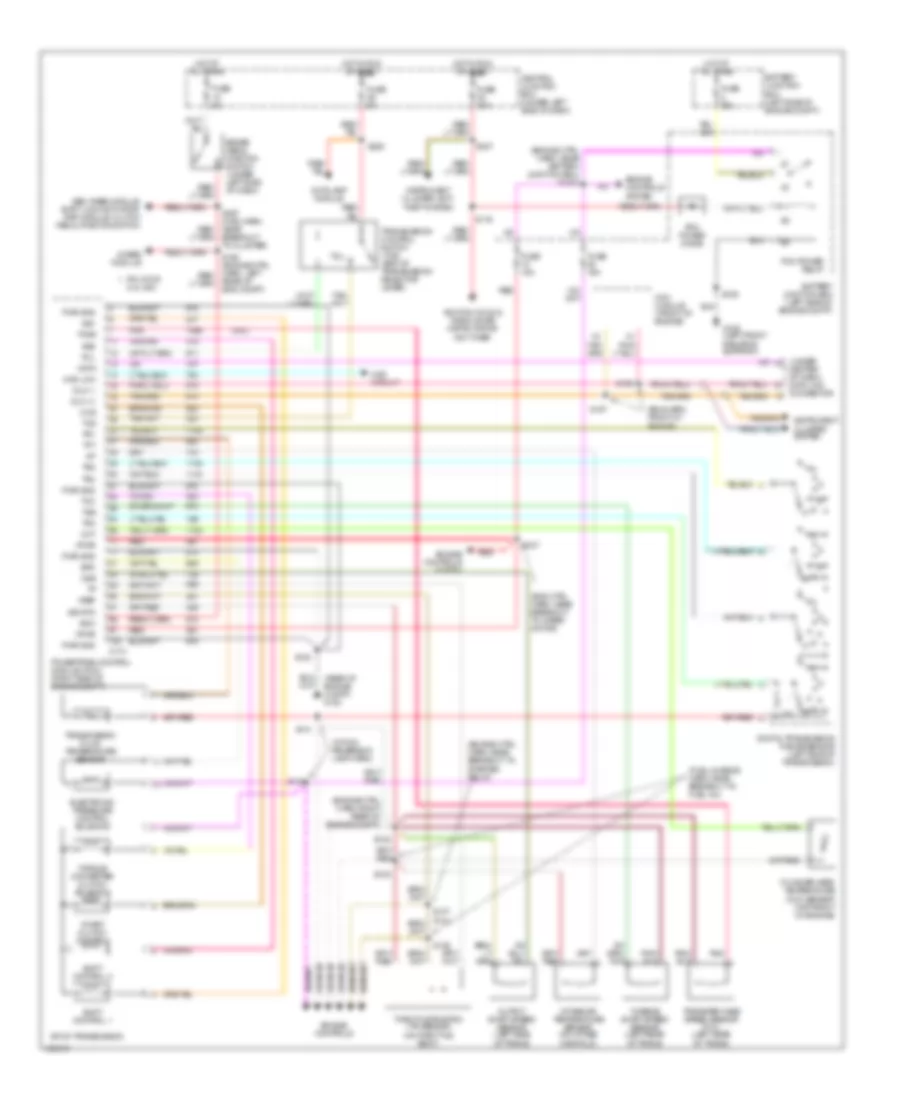
5.4L CNG, A/T Wiring Diagram, 4R100 for Ford Pickup F250 Super Duty 1999
List of elements for 5.4L CNG, A/T Wiring Diagram, 4R100 for Ford Pickup F250 Super Duty 1999:
- (5.4l)
- (eng ctrl harn, near breakout to wiper motor)
- (eng harn, front of engine)
- (engine ctrl harn, near battery junction box) s1003
- (engine ctrl harn, near breakout to starter relay)
- (engine ctrl harn, right rear of engine compt)
- (fuel charge harn, near breakout to fuel inj)
- (rear of engine compt) g123
- (under
- (within reversing lamp harn)
- 4r100 transmission
- 4wabs module
- 4wd circuit
- 4wd low
- Autolamp module
- Battery junction box (left side of engine compt)
- Boo
- Brake pedal position switch (under left side of dash)
- Breakout to cluster)
- C174
- Ccs
- Center of dash) data link connector
- Central junction box (under left side of dash)
- Cht
- Coast clutch control
- Cylinder head temperature (cht) sensor (top front of engine)
- Data
- Digital transmission range sensor (left side of transmission)
- Dlc (+)
- Dlc (-)
- Electronic pressure control solenoid
- Engine controls
- Engine controls system
- Epc
- Fuse 15a
- Fuse 30a
- Fuse 5a
- G108 (left front radiator support)
- Gem, rabs module, shift lock actuator, rap module, clutch pedal position switch
- Hot at all times
- Hot in run or start
- Iat
- Ignition coils & radio noise capacitor or ngv timer
- Instrument cluster system
- Instrument cluster, anti- theft system
- Intake air temperature sensor (on intake manifold)
- Ngv module (front of engine)
- Oss
- Output shaft speed sensor (left side of trans)
- Pcm power diode
- Pcm power relay
- Pin 3 for 5.4l ngv
- Pnk
- Powertrain control module (pcm) (right side of engine compt)
- Pwr gnd
- R p
- Rear of eng compt)
- Red
- S100
- S106
- S116
- S127
- S135
- S136
- S137 (5.4l)
- S138
- S140
- S141
- S156
- S157
- S225
- S237
- Shift control 1
- Shift control 2
- Sig rtn
- Ss1
- Ss2
- Tcc
- Tcil
- Tcs
- Tcss
- Tft
- Throttle position (tp) sensor (on throttle body)
- Torque converter clutch solenoid
- Tr1
- Tr2
- Tr3
- Tr4
- Transfer case speed sensor (5.4l) (left rear of trans)
- Transmission control switch (tcs) (end of transmission selector lever)
- Transmission fluid temperature sensor
- Tss
- Turbine shaft speed sensor (left rear of trans)
- Vpwr
- Vref
5.4L, A/T Wiring Diagram, 4R100 for Ford Pickup F250 Super Duty 1999
List of elements for 5.4L, A/T Wiring Diagram, 4R100 for Ford Pickup F250 Super Duty 1999:
- (5.4l)
- (eng ctrl harn, near breakout to wiper motor)
- (eng harn, front of engine)
- (engine ctrl harn, near battery junction box) s1003
- (engine ctrl harn, near breakout to starter relay)
- (engine ctrl harn, right rear of engine compt)
- (fuel charge harn, near breakout to fuel inj)
- (rear of engine compt) g123
- (under
- (within reversing lamp harn)
- 4r100 transmission
- 4wabs module
- 4wd circuit
- 4wd low
- Autolamp module
- Battery junction box (left side of engine compt)
- Boo
- Brake pedal position switch (under left side of dash)
- Breakout to cluster)
- C174
- Ccs
- Center of dash) data link connector
- Central junction box (under left side of dash)
- Cht
- Coast clutch control
- Cylinder head temperature (cht) sensor (top front of engine)
- Data
- Digital transmission range sensor (left side of transmission)
- Dlc (+)
- Dlc (-)
- Electronic pressure control solenoid
- Engine controls
- Engine controls system
- Epc
- Fuse 15a
- Fuse 30a
- Fuse 5a
- G108 (left front radiator support)
- Gem, rabs module, shift lock actuator, rap module, clutch pedal position switch
- Hot at all times
- Hot in run or start
- Iat
- Ignition coils & radio noise capacitor or ngv timer
- Instrument cluster system
- Instrument cluster, anti- theft system
- Intake air temperature sensor (on intake manifold)
- Ngv module (front of engine)
- Oss
- Output shaft speed sensor (left side of trans)
- Pcm power diode
- Pcm power relay
- Pin 3 for 5.4l ngv
- Pnk
- Powertrain control module (pcm) (right side of engine compt)
- Pwr gnd
- R p
- Rear of eng compt)
- Red
- S100
- S106
- S116
- S127
- S135
- S136
- S137 (5.4l)
- S138
- S140
- S141
- S156
- S157
- S225
- S237
- Shift control 1
- Shift control 2
- Sig rtn
- Ss1
- Ss2
- Tcc
- Tcil
- Tcs
- Tcss
- Tft
- Throttle position (tp) sensor (on throttle body)
- Torque converter clutch solenoid
- Tr1
- Tr2
- Tr3
- Tr4
- Transfer case speed sensor (5.4l) (left rear of trans)
- Transmission control switch (tcs) (end of transmission selector lever)
- Transmission fluid temperature sensor
- Tss
- Turbine shaft speed sensor (left rear of trans)
- Vpwr
- Vref
5.4L, A/T Wiring Diagram, 4R70W for Ford Pickup F250 Super Duty 1999
List of elements for 5.4L, A/T Wiring Diagram, 4R70W for Ford Pickup F250 Super Duty 1999:
- (eng ctrl harn, right rear of eng compt)
- (engine ctrl harn, near breakout to starter relay)
- (fuel charge harn, near breakout to fuel inj)
- (in reversing lamp harn)
- (rear of engine compt) g123
- (under
- 4r70w transmission (mounted under center of vehicle)
- 4wabs module
- 4wd circuit
- 4wd low
- Autolamp module
- Battery junction box (left side of engine compt)
- Boo
- Brake pedal position switch (under left side of dash)
- C174
- Center of dash) data link connector
- Central junction box (under left side of dash)
- Cht
- Cylinder head temperature (cht) sensor (top front of engine)
- Data
- Digital transmission range sensor (left side of transmission)
- Dlc (+)
- Dlc (-)
- Electronic pressure control solenoid
- Engine controls system
- Epc
- Fuse 15a
- Fuse 30a
- Fuse 5a
- G108 (left front radiator support)
- Gem, rabs module, shift lock actuator, rap module, clutch pedal position switch
- Hot at all times
- Hot in run or start
- Iat
- Ignition coils, radio noise capacitor
- Instrument cluster system
- Instrument cluster, anti- theft system
- Intake air temperature sensor (on intake manifold)
- Oss
- Output shaft speed sensor (left side of trans)
- Pcm power diode
- Pcm power relay
- Pnk
- Powertrain control module (pcm) (right side of engine compt)
- Pwr gnd
- R p
- Red
- S100
- S106
- S116
- S127 (eng ctrl harn, near breakout to wiper motor)
- S135
- S136
- S137
- S138
- S140
- S141
- S160 (engine ctrl harn, left rear of eng compt)
- S225
- S237
- S297 (main harn, near breakout to cluster)
- Shift solenoids (ss)
- Sig rtn
- Ss1
- Ss2
- Tcc
- Tcil
- Tcs
- Tcss
- Tft
- Throttle position (tp) sensor (on throttle body)
- Torque converter clutch (tcc) solenoid
- Tr1
- Tr2
- Tr3
- Tr4
- Transfer case speed sensor (left rear of trans)
- Transmission control switch (tcs) (end of transmission selector lever)
- Transmission fluid temperature sensor
- Tss
- Turbine shaft speed sensor (left rear of trans)
- Vpwr
- Vref

 Dansk
Dansk Deutsch
 Ελληνικά
 English
 English
 Español
 Suomi
Suomi Français
 Français
 עברית
עברית Hrvatski
 Magyar
 Italiano
 日本語
日本語 한국어
한국어 Nederlands
 Polski
 Português
 Português
 Română
 Русский
 Slovenčina
 Slovenščina
 Svenska
 Türkçe
 中文 (中国)