TRANSMISSION
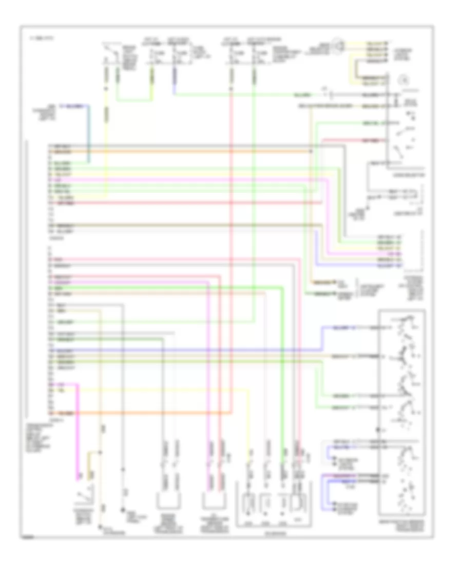
Transmission Wiring Diagram for Volvo 960 1995
List of elements for Transmission Wiring Diagram for Volvo 960 1995:
- (below park brake lever)
- 15i nca
- 1995 vftc c
- 50s nca
- 8/38
- 8/39
- 8/40
- 8/41
- A nca
- B nca
- Bl nca
- Brake light switch (above brake pedal)
- C nca
- C128
- C129
- C130
- Conn a
- Conn b
- Engine compartment fuse/relay block
- Engine speed sensor (left front of transmission)
- Exterior lights system
- Fuse 15a
- Fuse 5a
- Fuse block (left i/p)
- G112 (on engine)
- G200 (left kick panel)
- G206 (center of i/p)
- Gear position sensor (right side of transmission)
- Gear selector illumination
- Hot at all times
- Hot in run or start
- Hot with engine running
- Instrument cluster system
- Interior lights system
- J/c
- J/c (center of i/p)
- Kickdown switch (behind left i/p)
- Mode selector
- Motronic system mfi control module (below left i/p)
- Nca
- O/d indic
- Obd diagnostic socket (left i/p)
- Oil temperature sensor (right side of transmission)
- Pa nca
- Pnk
- Solenoids
- Solid state
- Speedo- meter
- Starting/ charging system
- Sth
- Sthg
- Transmission control module (below left i/p, right of steering column)
 Dansk
Dansk Deutsch
 Ελληνικά
 English
 English
 Español
 Suomi
Suomi Français
 Français
 עברית
עברית Hrvatski
 Magyar
 Italiano
 日本語
日本語 한국어
한국어 Nederlands
 Polski
 Português
 Português
 Română
 Русский
 Slovenčina
 Slovenščina
 Svenska
 Türkçe
 中文 (中国)
 Čeština