TRANSMISSION
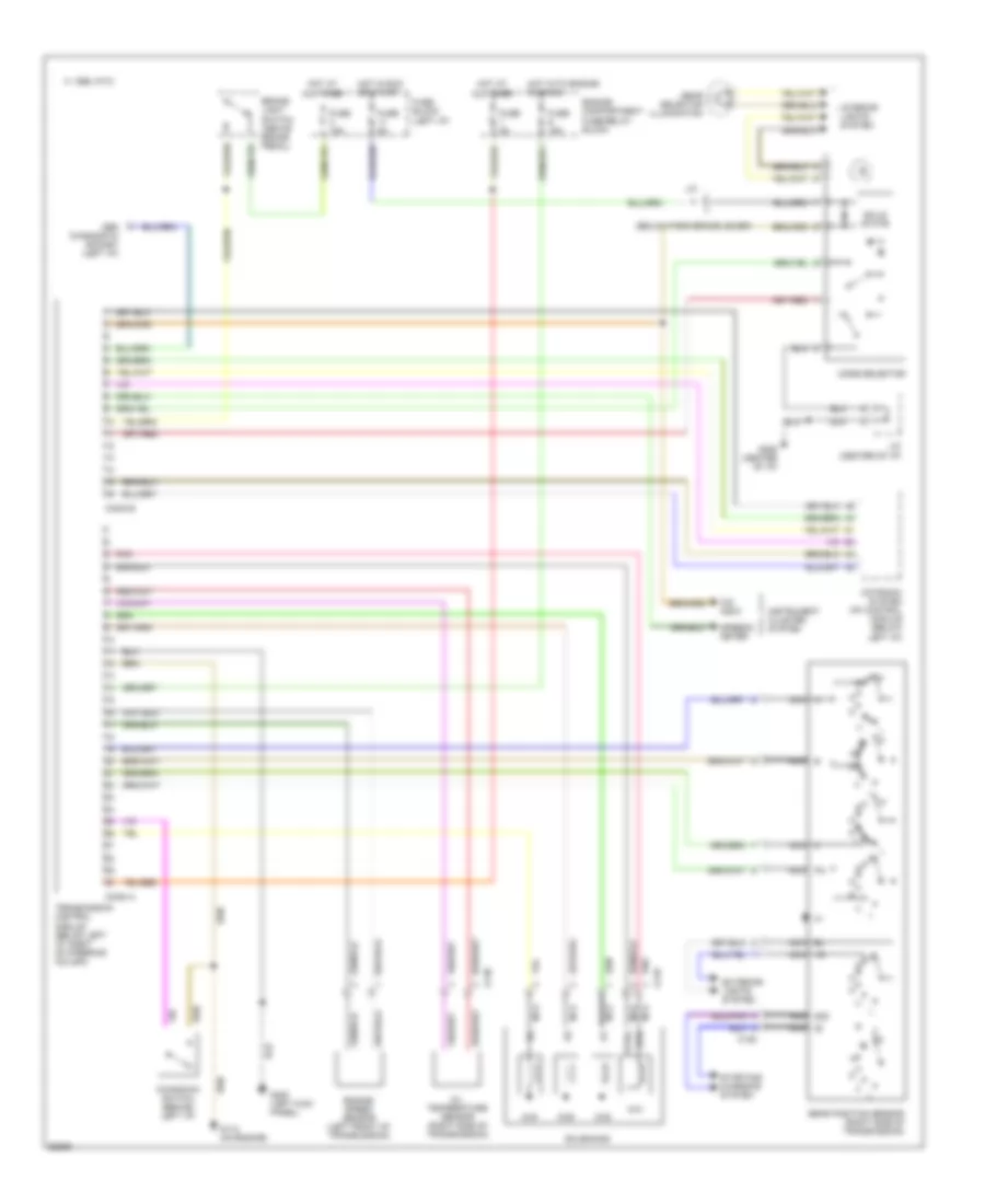
Transmission Wiring Diagram for Volvo 960 1995
List of elements for Transmission Wiring Diagram for Volvo 960 1995:
- (below park brake lever)
- 15i nca
- 1995 vftc c
- 50s nca
- 8/38
- 8/39
- 8/40
- 8/41
- A nca
- B nca
- Bl nca
- Brake light switch (above brake pedal)
- C nca
- C128
- C129
- C130
- Conn a
- Conn b
- Engine compartment fuse/relay block
- Engine speed sensor (left front of transmission)
- Exterior lights system
- Fuse 15a
- Fuse 5a
- Fuse block (left i/p)
- G112 (on engine)
- G200 (left kick panel)
- G206 (center of i/p)
- Gear position sensor (right side of transmission)
- Gear selector illumination
- Hot at all times
- Hot in run or start
- Hot with engine running
- Instrument cluster system
- Interior lights system
- J/c
- J/c (center of i/p)
- Kickdown switch (behind left i/p)
- Mode selector
- Motronic system mfi control module (below left i/p)
- Nca
- O/d indic
- Obd diagnostic socket (left i/p)
- Oil temperature sensor (right side of transmission)
- Pa nca
- Pnk
- Solenoids
- Solid state
- Speedo- meter
- Starting/ charging system
- Sth
- Sthg
- Transmission control module (below left i/p, right of steering column)
 English