ENGINE PERFORMANCE
2.9L
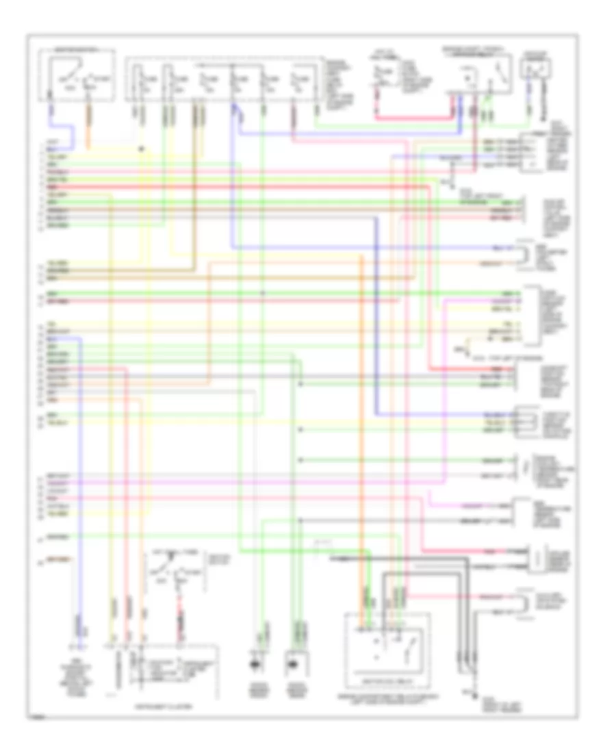
2.9L, Engine Performance Wiring Diagrams (1 of 2) for Volvo 960 1995

List of elements for 2.9L, Engine Performance Wiring Diagrams (1 of 2) for Volvo 960 1995:
- (top left front of engine)
- A12
- A30
- Automatic climate control a/c relay
- Aw30-40/43 control module
- B15
- B16
- Ecc control module
- Engine cooling fan relay & high speed press. sensor
- Engine cooling fan relay & low speed pressure sensor
- Fuel injection system main relay
- Fuel injectors
- Fuel pump (in fuel tank)
- Fuel pump relay
- Fuse 50a
- G112 (lower left side of engine)
- G134
- G134 (top left of engine)
- G300 (below left front seat)
- Hot at all times
- Ignition coils
- Low-pressure sensor
- Main fuse box (right side of engine compt.)
- Motronic 1 power stage (front of intake manifold)
- Motronic 2 power stage (rear of intake manifold)
- Motronic system mfi control module (under left dash)
- Nca
- Pnk
- Red
- Relay unit
- Service socket
- Spark plugs
2.9L, Engine Performance Wiring Diagrams (2 of 2) for Volvo 960 1995
List of elements for 2.9L, Engine Performance Wiring Diagrams (2 of 2) for Volvo 960 1995:
- (engine compt. f/r box) air pump relay
- (top left of engine)
- 15i
- 30i
- A13
- Acc
- Air pump motor
- Auxiliary air system solenoid
- Camshaft position sensor (top right rear of engine)
- Egr converter (left strut tower)
- Egr temperature sensor (left side of engine)
- Engine compart- ment fuse/ relay box (left side of engine compt.)
- Engine compartment relay/fuse box (left side of engine compt.)
- Engine coolant temperature sensor (right rear of engine)
- Front fender)
- Fuse 15a
- Fuse 25a
- Fuse 50a
- Fuse 5a
- G100 (front of left front fender)
- G101 (right
- G134
- G134 (top left front of engine)
- Heated oxygen sensor (left rear of engine)
- Hot at all times
- Idle air control valve (left side of engine compart- ment)
- Ignition coil relay
- Ignition switch
- Impulse sensor (rear of engine)
- Instrument cluster
- Instrument cluster fuse
- Knock sensor (front)
- Knock sensor (rear)
- Main fuse block (right side of engine compt.)
- Malfunc- tion indicator lamp
- Mass air flow sensor (left side of engine compart- ment)
- Nca
- Obd diagnostic socket (partial) (behind left shock tower)
- Off
- Pnk
- Red
- Run
- Speedometer
- Start
- Tach
- Throttle position sensor (on intake manifold)