SUPPLEMENTAL RESTRAINTS
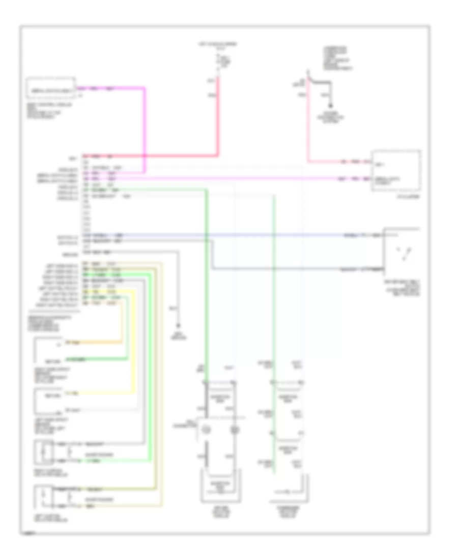
Supplemental Restraint Wiring Diagram for Saturn LW300 2001
List of elements for Supplemental Restraint Wiring Diagram for Saturn LW300 2001:
- A10
- A11
- A12
- A13
- A14
- A15
- A16
- A17
- A18
- B tan
- Body control module (bcm) (mounted to top of glove box)
- D10
- D5 (or f8)
- Driver inflator module
- Driver seat belt switch (in driver's seat belt buckle)
- Ground
- Hot in run & crank
- I/p cluster
- Ign 1
- Ign 1 fuse 10a
- Left curtain inflator module
- Left sattelite in
- Left sattelite out
- Left side impact sensor (on lower left "b" pillar)
- Left side mod hi
- Left side mod lo
- Module hi
- Module lo
- Nca
- Passenger inflator module
- Pnk
- Power distribution system
- Return
- Right curtain inflator module
- Right sattelite in
- Right sattelite out
- Right side impact sensor (on lower right "b" pillar)
- Right side mod hi
- Right side mod lo
- Roll connector
- Sdm ground
- Sensing & diagnostic module (sdm) (under rear of floor console)
- Serial data class 2
- Shorting bar
- Switch hi
- Switch lo
- Tan
- Underhood fuse block (uhfb) (left side of engine compartment)
 Čeština
 Deutsch
 Ελληνικά
 English
 English
 Español
 Suomi
Suomi Français
 Français
 עברית
עברית Hrvatski
 Magyar
 Italiano
 日本語
日本語 한국어
한국어 Nederlands
 Polski
 Português
 Português
 Română
 Русский
 Slovenčina
 Slovenščina
 Svenska
 Türkçe
 中文 (中国)
 Dansk
Dansk