AIR CONDITIONING
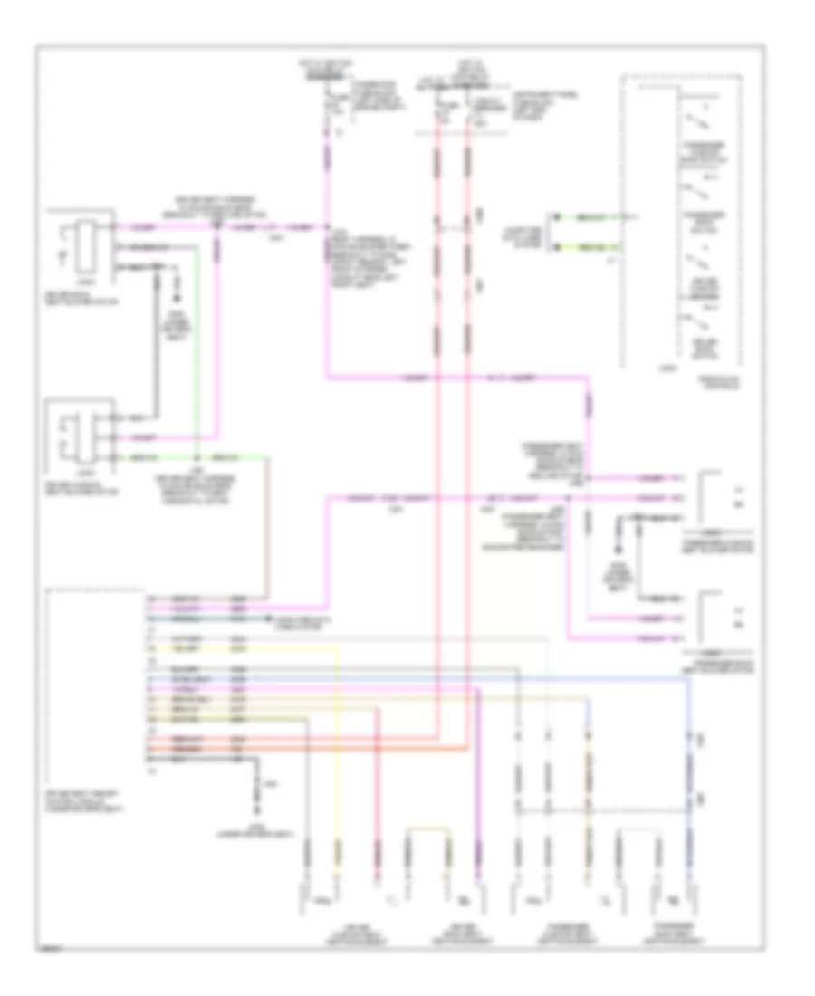
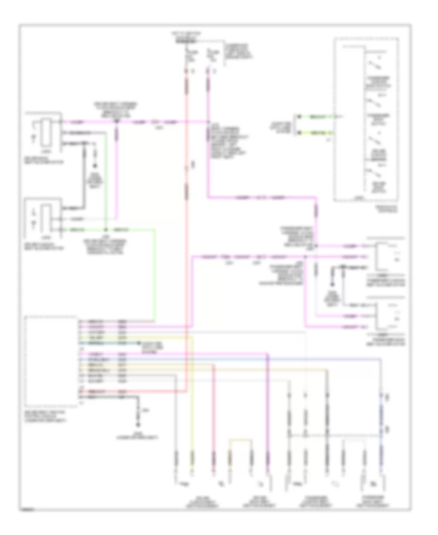
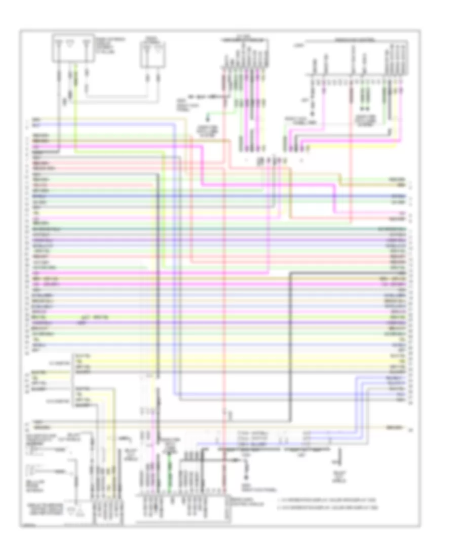
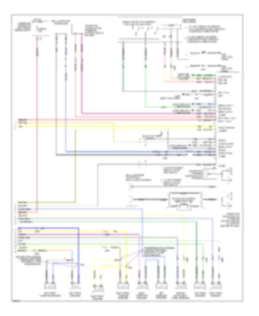
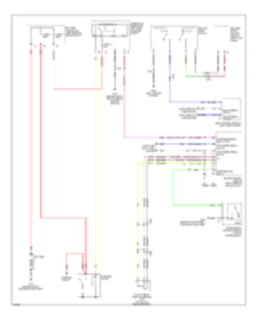
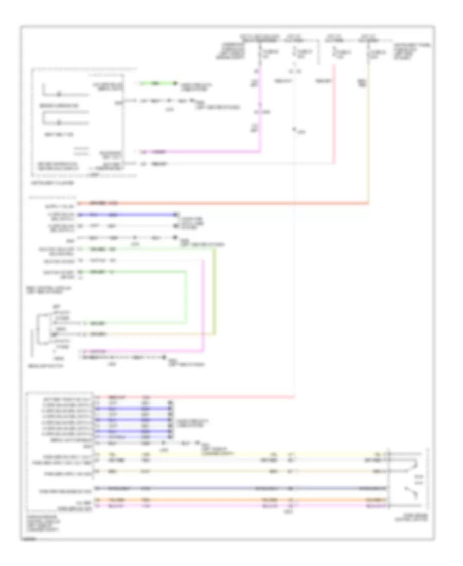
Automatic A/C Wiring Diagram, Dual Fans (1 of 6) for Saab 9-5 Aero 2011
 https://portal-diagnostov.com/license.html
Automotive Electricians Portal FZCO
Automotive Electricians Portal FZCO
https://portal-diagnostov.com/license.html
https://portal-diagnostov.com/license.html
Automotive Electricians Portal FZCO
Automotive Electricians Portal FZCO
List of elements for Automatic A/C Wiring Diagram, Dual Fans (1 of 6) for Saab 9-5 Aero 2011:
- (left center of dash)
- (or tan)
- 5-volt ref
- A/c compressor solenoid valve (rear of a/c compressor)
- A/c refrigerant pressure sensor
- Air quality sens sig
- Auxiliary heater cntl
- Auxiliary heater status sig
- Battery positive voltage
- Blower mtr spd ctrl
- Body control module (left end of dash)
- Computer data lines system
- Defogger system
- Duct lower air temperature sensor (mounted on hvac module)
- Duct upper air temperature sensor (mounted on hvac module)
- Electric variable displacement ctrl
- Electric variable displacement sply
- G206
- Gnd
- Humidity sens sig
- Humidity temp sens sig
- Hvac control module (center of dash)
- Inside air temp sens sig
- J299
- Linear interconnect network bus 9
- Low ref
- Low speed gmlan serial data
- Lower air temp sens sig
- Rear blower mtr spd ctrl
- Rear defog rly ctrl
- Run relay coil cntl
- Run rly coil ctrl
- Security ind ctrl
- Solar sens drv sig
- Twilight sentinel delay sig
- Underhood fuse block (left side of engine compt)
- Upper air temp sens sig
- Windshield temp sens sig
- X108
- X118
- X200
- X201
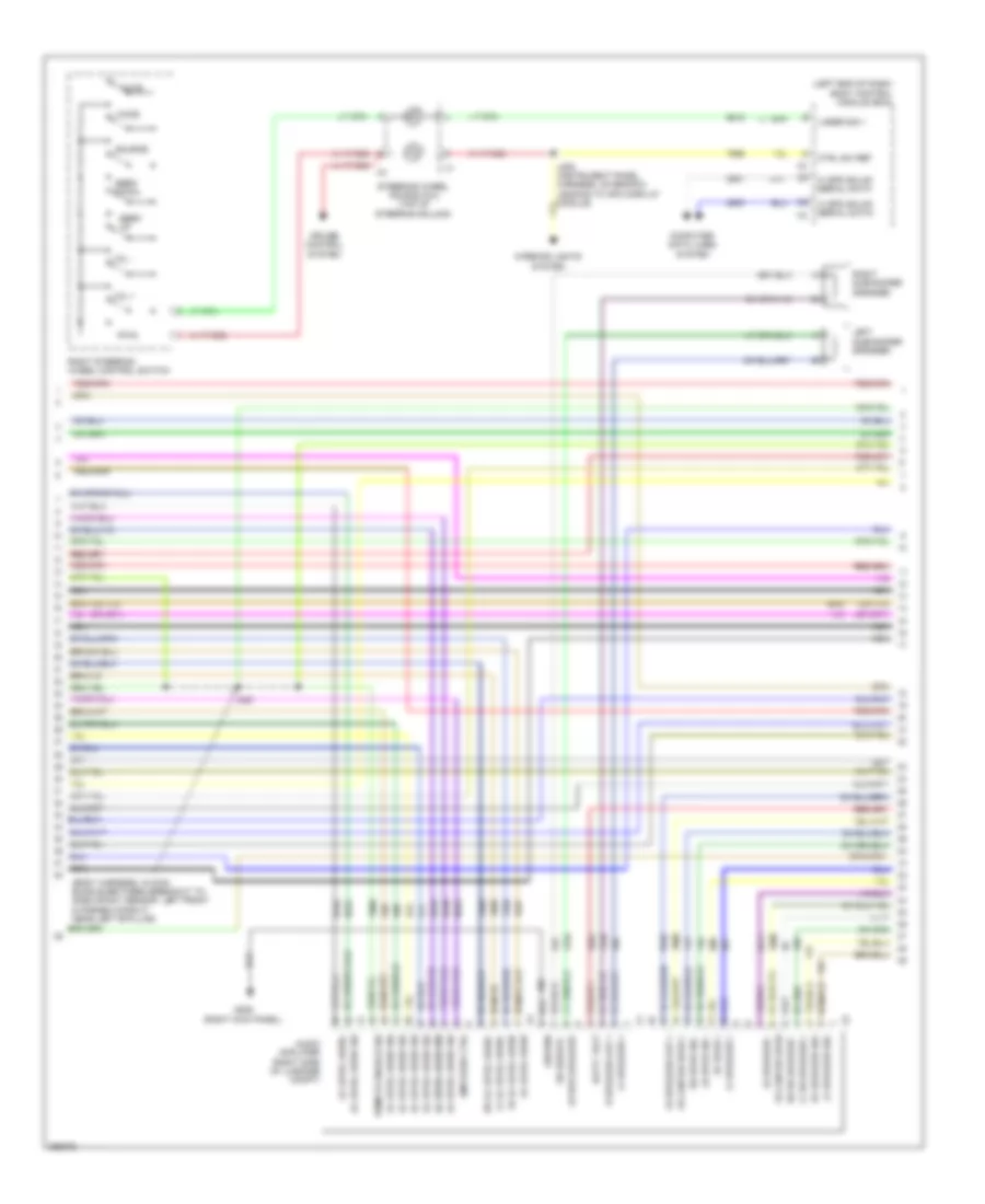
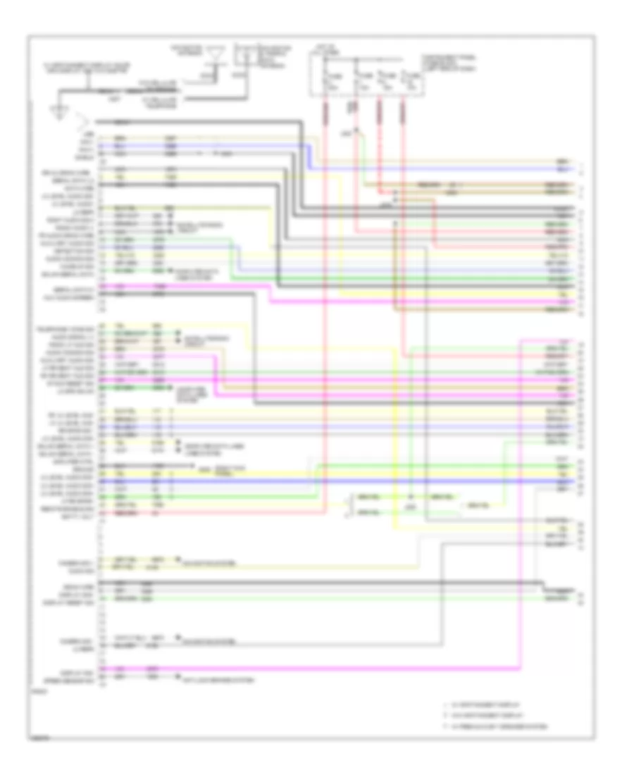
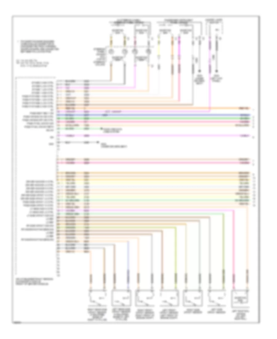
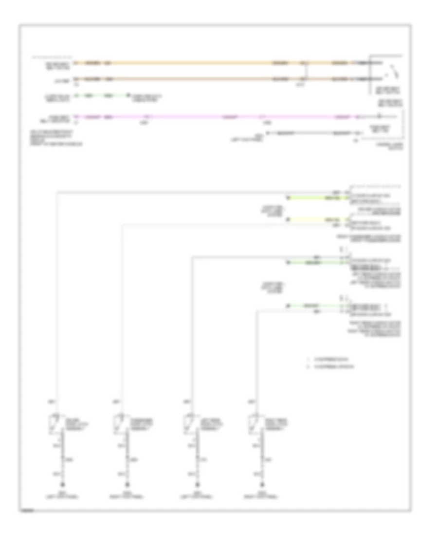
Automatic A/C Wiring Diagram, Dual Fans (2 of 6) for Saab 9-5 Aero 2011
List of elements for Automatic A/C Wiring Diagram, Dual Fans (2 of 6) for Saab 9-5 Aero 2011:
- (2.8l) air quality sensor
- (engine harness, in formed conduit by throttle body)
- (on branch leading to remote control door lock receiver)
- (or 151)
- (or 2761)
- (or tan)
- 2.0l
- 2.8l
- 5v ref 1
- A/c refrigerant press
- Ambient light/sunload sensor (top center of dash)
- Auxiliary blower motor
- Auxiliary blower motor control module
- Computer data lines system
- Coolant temp sens sig
- Engine control module (right rear of engine compt)
- Engine controls system
- Engine coolant temperature sensor (right rear of engine)
- Fuse 10a
- Fuse 5a
- Fuse 7.5a
- G109 (engine compt, on left strut tower)
- G201 (left kick panel)
- Hi spd cooling fan rly ctrl
- Hot at all times
- Hot w/ ignition main relay energized
- J126 (2.8l)
- J131
- J136
- J204
- J318
- Logic
- Lw spd cooling fan rly ctrl
- Rear body fuse block (left side of luggage compt)
- Sens sig
- Sig gnd
- Underhood fuse block (left side of engine compt)
- Windshield temperature & inside moisture sensor (top center of windshield)
- X200
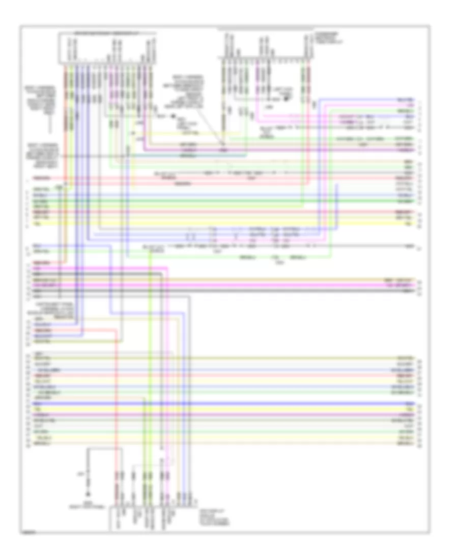
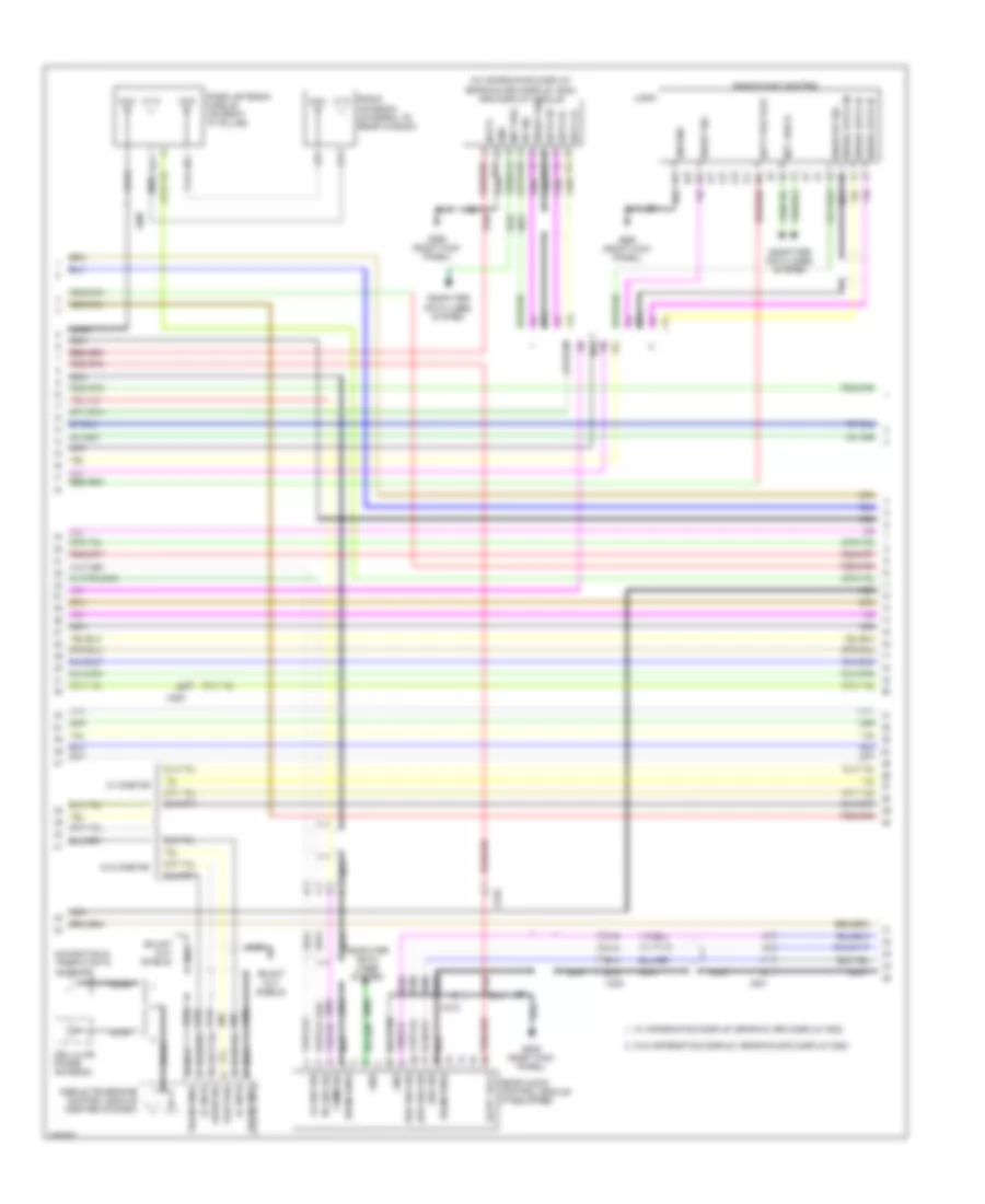
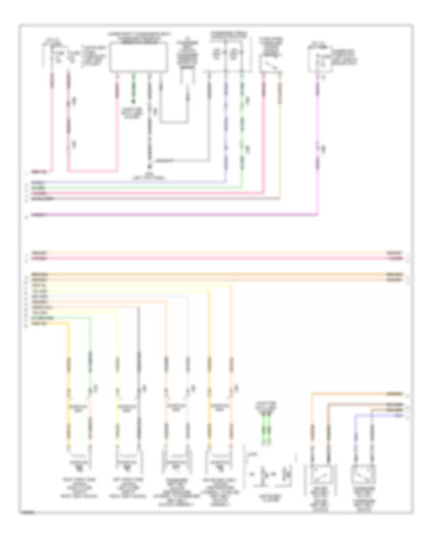
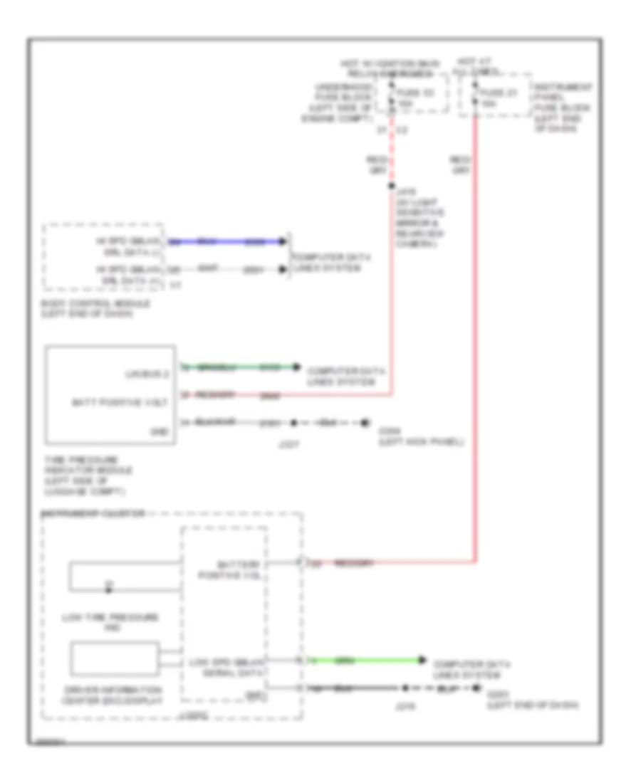
Automatic A/C Wiring Diagram, Dual Fans (3 of 6) for Saab 9-5 Aero 2011
List of elements for Automatic A/C Wiring Diagram, Dual Fans (3 of 6) for Saab 9-5 Aero 2011:
- (right side of dash) blower motor
- (right side of dash) blower motor control module
- (under driver's seat)
- A/c evaporator temperature sensor
- Auxiliary heater ctrl
- Auxiliary underhood fuse block
- Batt + volt
- Batt positive volt
- Blower mtr fan ctrl
- Blower mtr spd ctrl
- Blower mtr sply volt
- Computer data lines system
- Electrical auxiliary heater (part of hvac module)
- Fuse 100a
- Fuse 10a
- Fuse 50a
- G111 (engine compt, rearward of battery)
- G305
- Gnd
- Heater status sig
- Hot at all times
- Instrument cluster
- Instrument panel fuse block (left end of dash)
- J207
- J298
- Left duct lower air temperature sensor (mounted on hvac module)
- Left duct upper air temperature sensor (mounted on hvac module)
- Red
- Right duct lower air temperature sensor (mounted on hvac module)
- Right duct upper air temperature sensor (mounted on hvac module)
- Run/crank ign 1 volt
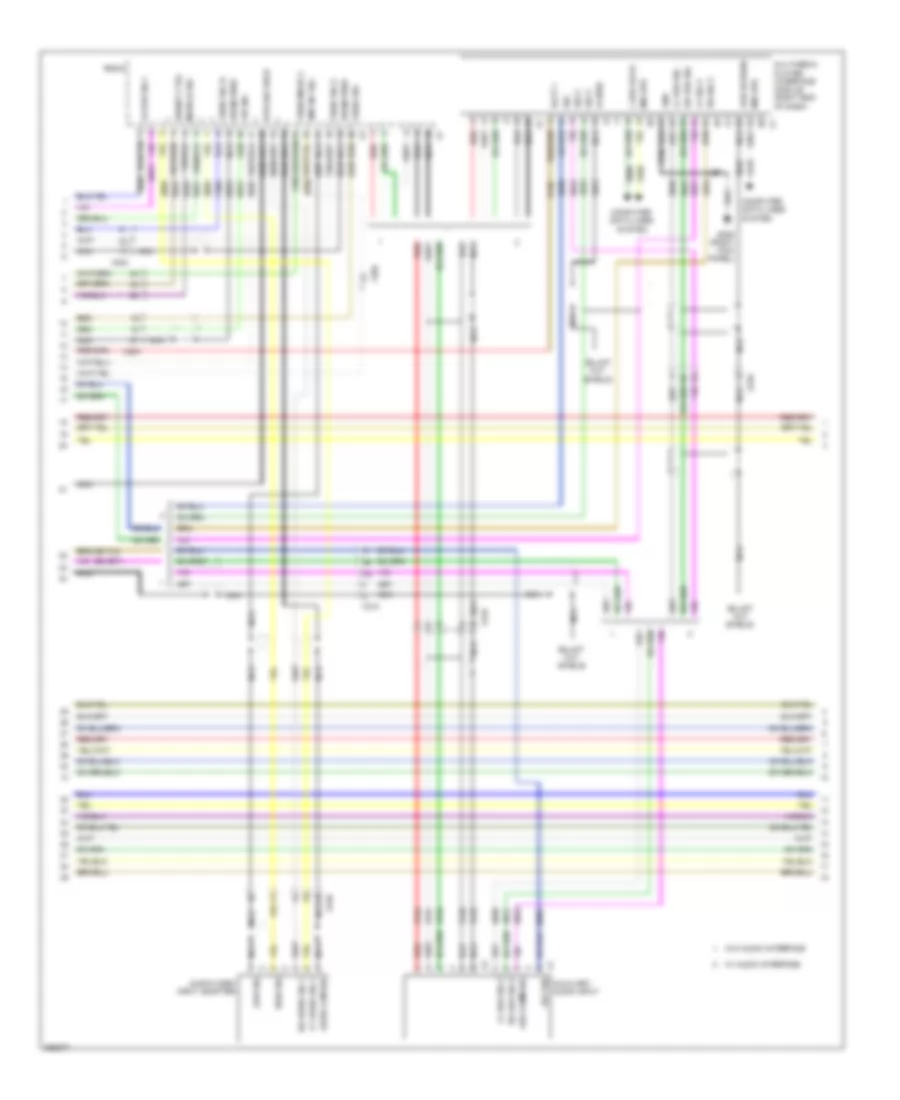
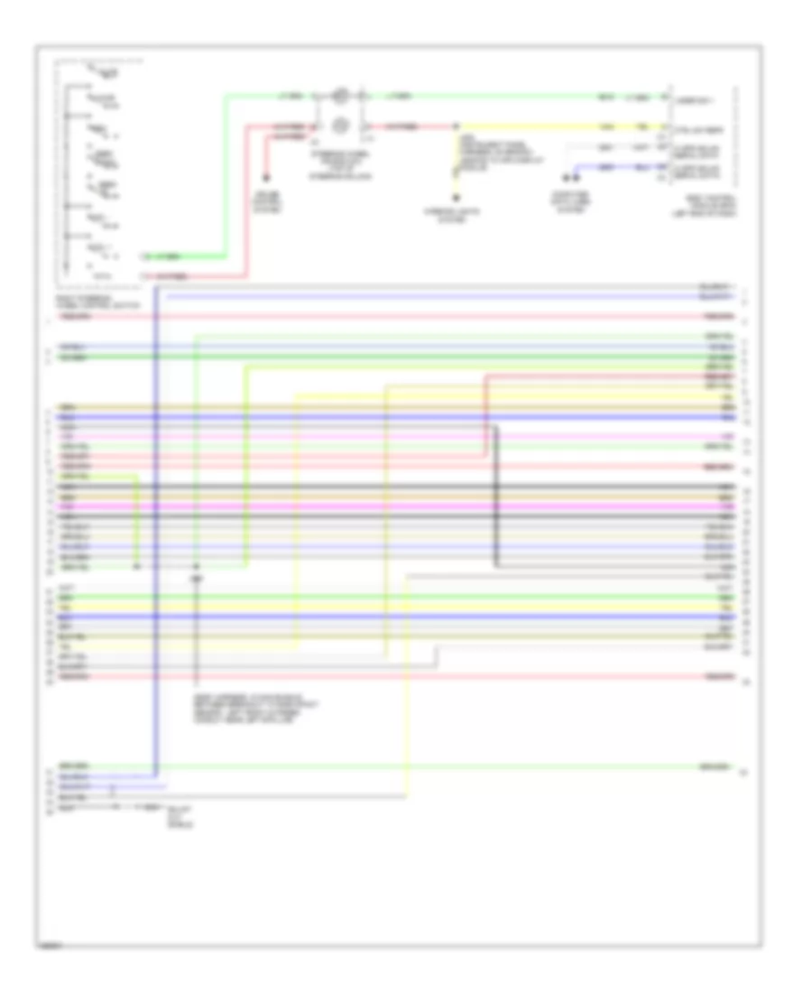
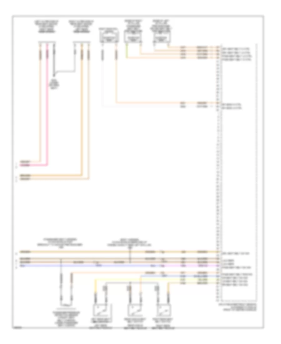
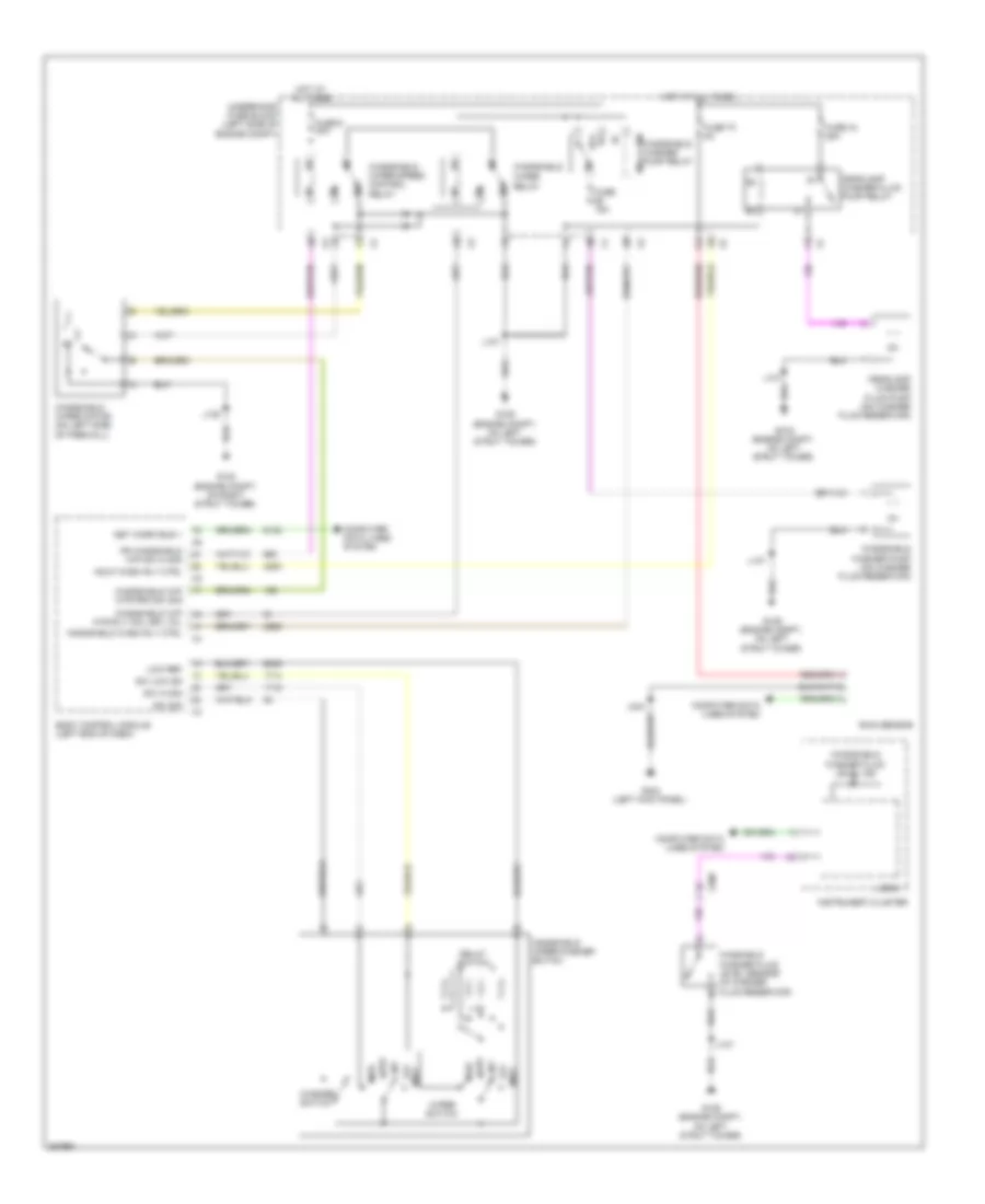
Automatic A/C Wiring Diagram, Dual Fans (4 of 6) for Saab 9-5 Aero 2011
List of elements for Automatic A/C Wiring Diagram, Dual Fans (4 of 6) for Saab 9-5 Aero 2011:
- (body harness, in branch to body control module, near breakout to left front door inline)
- (body harness, in main bundle between breakout to left front door inline & g201)
- A/c request switch
- Air inlet door actuator
- Air inlet dr stepper mtr ctrl 1
- Air inlet dr stepper mtr ctrl 2
- Air inlet dr stepper mtr ctrl 3
- Air inlet dr stepper mtr ctrl 4
- Air recirculation door motor
- Air recirculation switch
- Auto switch
- Auxiliary mode door actuator
- Blower switch
- Defog switch
- Defrost switch
- Evap core temp sens sig
- Floor switch
- Hvac control module (center of dash)
- Hvac mtr sply volt
- Inlet dr stepper mtr ctrl 1
- Inlet dr stepper mtr ctrl 2
- Inlet dr stepper mtr ctrl 3
- Inlet dr stepper mtr ctrl 4
- J232
- J233
- Left air temperature door actuator
- Lf dr temp stepper mtr ctrl 1
- Lf dr temp stepper mtr ctrl 2
- Lf dr temp stepper mtr ctrl 3
- Lf dr temp stepper mtr ctrl 4
- Logic
- Lwr lf air temp sens sig
- Lwr rh air temp sens sig
- Mode door actuator
- Mode dr stepper mtr ctrl 1
- Mode dr stepper mtr ctrl 2
- Mode dr stepper mtr ctrl 3
- Mode dr stepper mtr ctrl 4
- Mode ind
- Mode switch
- Panel switch
- Pnk
- Radio/ hvac controls
- Rear mode motor sply voltage
- Red
- Rh dr temp stepper mtr pass ctrl 1
- Rh dr temp stepper mtr pass ctrl 2
- Rh dr temp stepper mtr pass ctrl 3
- Rh dr temp stepper mtr pass ctrl 4
- Right air temperature door actuator
- Sens low reference
- Temp dr stepper mtr ctrl 1
- Temp dr stepper mtr ctrl 2
- Temp dr stepper mtr ctrl 3
- Temp dr stepper mtr ctrl 4
- Tempe- rature down switch
- Tempe- rature up switch
- Upper left air temp sens sig
- Upper rh air temp sens sig
- Zone switch
Automatic A/C Wiring Diagram, Dual Fans (5 of 6) for Saab 9-5 Aero 2011
List of elements for Automatic A/C Wiring Diagram, Dual Fans (5 of 6) for Saab 9-5 Aero 2011:
- (not used)
- Cooling fan high speed relay
- Cooling fan low speed relay
- Cooling fan relay
- Cooling fan speed control relay
- Fuse 10a
- Fuse 30a
- Fuse 42 20a
- G109 (engine compt, on left strut tower)
- Hot at all times
- Hot w/ engine control module relay energized
- J115 (engine harness, between fuse block underhood & g120)
- J137
- Left cooling fan motor (behind radiator)
- Underhood fuse block (left side of engine compt)
- X117
- X119
- X3 (not used)
Automatic A/C Wiring Diagram, Dual Fans (6 of 6) for Saab 9-5 Aero 2011
List of elements for Automatic A/C Wiring Diagram, Dual Fans (6 of 6) for Saab 9-5 Aero 2011:
- (engine compartment, left center of radiator support)
- (engine cooling harness, on branch, between main bundle & relay block- underhood)
- (engine cooling harness, on branch, between main bundle & relay block-underhood)
- Cooling fan speed control 2 relay
- G106
- J105 (engine cooling harness, on branch, between main bundle & relay block - underhood)
- J106
- J107
- J108
- Left cooling fan medium speed relay
- Right cooling fan medium speed relay
- Right cooling fan motor (behind radiator)
- Underhood relay block (left side of engine compt)
- X117
Automatic A/C Wiring Diagram, Single Fan (1 of 5) for Saab 9-5 Aero 2011
List of elements for Automatic A/C Wiring Diagram, Single Fan (1 of 5) for Saab 9-5 Aero 2011:
- (left center of dash)
- (or tan)
- 5-volt ref
- A/c compressor solenoid valve (rear of a/c compressor)
- A/c refrigerant pressure sensor
- Air quality sens sig
- Auxiliary heater cntl
- Auxiliary heater status sig
- Battery positive voltage
- Blower mtr spd ctrl
- Body control module (left end of dash)
- Computer data lines system
- Defogger system
- Duct lower air temperature sensor (mounted on hvac module)
- Duct upper air temperature sensor (mounted on hvac module)
- Electric variable displacement ctrl
- Electric variable displacement sply
- G206
- Gnd
- Humidity sens sig
- Humidity temp sens sig
- Hvac control module (center of dash)
- Inside air temp sens sig
- J299
- Linear interconnect network bus 9
- Low ref
- Low speed gmlan serial data
- Lower air temp sens sig
- Rear blower mtr spd ctrl
- Rear defog rly ctrl
- Run relay coil cntl
- Run rly coil ctrl
- Security ind ctrl
- Solar sens drv sig
- Twilight sentinel delay sig
- Underhood fuse block (left side of engine compt)
- Upper air temp sens sig
- Windshield temp sens sig
- X108
- X118
- X200
- X201
Automatic A/C Wiring Diagram, Single Fan (2 of 5) for Saab 9-5 Aero 2011
List of elements for Automatic A/C Wiring Diagram, Single Fan (2 of 5) for Saab 9-5 Aero 2011:
- (2.8l) air quality sensor
- (on branch leading to remote control door lock receiver)
- (or 151)
- (or 2761)
- (or tan)
- 2.0l
- 2.8l
- 5v ref 1
- A/c refrigerant press
- Ambient light/sunload sensor (top center of dash)
- Auxiliary blower motor
- Auxiliary blower motor control module
- Computer data lines system
- Coolant temp sens sig
- Engine control module (right rear of engine compt)
- Engine coolant temperature sensor (right rear of engine)
- Engine main rly coil ctrl
- Fuse 10a
- Fuse 5a
- Fuse 7.5a
- G109 (engine compt, on left strut tower)
- G201 (left kick panel)
- Hi spd cooling fan rly ctrl
- Hot at all times
- Hot w/ ignition main relay energized
- J131
- J136
- J204
- J318
- Logic
- Lw spd cooling fan rly ctrl
- Rear body fuse block (left side of luggage compt)
- Sens sig
- Sig gnd
- Underhood fuse block (left side of engine compt)
- Windshield temperature & inside moisture sensor (top center of windshield)
- X200
Automatic A/C Wiring Diagram, Single Fan (3 of 5) for Saab 9-5 Aero 2011
List of elements for Automatic A/C Wiring Diagram, Single Fan (3 of 5) for Saab 9-5 Aero 2011:
- (right side of dash) blower motor
- (right side of dash) blower motor control module
- (under driver's seat)
- A/c evaporator temperature sensor
- Auxiliary heater ctrl
- Auxiliary underhood fuse block
- Batt + volt
- Batt positive volt
- Blower mtr fan ctrl
- Blower mtr spd ctrl
- Blower mtr sply volt
- Computer data lines system
- Electrical auxiliary heater (part of hvac module)
- Fuse 100a
- Fuse 10a
- Fuse 50a
- G111 (engine compt, rearward of battery)
- G305
- Gnd
- Heater status sig
- Hot at all times
- Instrument cluster
- Instrument panel fuse block (left end of dash)
- J207
- J298
- Left duct lower air temperature sensor (mounted on hvac module)
- Left duct upper air temperature sensor (mounted on hvac module)
- Red
- Right duct lower air temperature sensor (mounted on hvac module)
- Right duct upper air temperature sensor (mounted on hvac module)
- Run/crank ign 1 volt
Automatic A/C Wiring Diagram, Single Fan (4 of 5) for Saab 9-5 Aero 2011
List of elements for Automatic A/C Wiring Diagram, Single Fan (4 of 5) for Saab 9-5 Aero 2011:
- (body harness, in branch to body control module, near breakout to left front door inline)
- (body harness, in main bundle between breakout to left front door inline & g201)
- A/c request switch
- Air inlet door actuator
- Air inlet dr stepper mtr ctrl 1
- Air inlet dr stepper mtr ctrl 2
- Air inlet dr stepper mtr ctrl 3
- Air inlet dr stepper mtr ctrl 4
- Air recirculation door motor
- Air recirculation switch
- Auto switch
- Auxiliary mode door actuator
- Blower switch
- Defog switch
- Defrost switch
- Evap core temp sens sig
- Floor switch
- Hvac control module (center of dash)
- Hvac mtr sply volt
- Inlet dr stepper mtr ctrl 1
- Inlet dr stepper mtr ctrl 2
- Inlet dr stepper mtr ctrl 3
- Inlet dr stepper mtr ctrl 4
- J232
- J233
- Left air temperature door actuator
- Lf dr temp stepper mtr ctrl 1
- Lf dr temp stepper mtr ctrl 2
- Lf dr temp stepper mtr ctrl 3
- Lf dr temp stepper mtr ctrl 4
- Logic
- Lwr lf air temp sens sig
- Lwr rh air temp sens sig
- Mode door actuator
- Mode dr stepper mtr ctrl 1
- Mode dr stepper mtr ctrl 2
- Mode dr stepper mtr ctrl 3
- Mode dr stepper mtr ctrl 4
- Mode ind
- Mode switch
- Panel switch
- Pnk
- Radio/ hvac controls
- Rear mode motor sply voltage
- Red
- Rh dr temp stepper mtr pass ctrl 1
- Rh dr temp stepper mtr pass ctrl 2
- Rh dr temp stepper mtr pass ctrl 3
- Rh dr temp stepper mtr pass ctrl 4
- Right air temperature door actuator
- Sens low reference
- Temp dr stepper mtr ctrl 1
- Temp dr stepper mtr ctrl 2
- Temp dr stepper mtr ctrl 3
- Temp dr stepper mtr ctrl 4
- Temperature down switch
- Temperature up switch
- Upper left air temp sens sig
- Upper rh air temp sens sig
- Zone switch
Automatic A/C Wiring Diagram, Single Fan (5 of 5) for Saab 9-5 Aero 2011
List of elements for Automatic A/C Wiring Diagram, Single Fan (5 of 5) for Saab 9-5 Aero 2011:
- (engine harness, between fuse block-underhood & g120)
- (not used)
- Cooling fan high speed relay
- Cooling fan medium speed 1 relay
- Cooling fan medium speed 2 relay
- Cooling fan motor (behind radiator)
- Cooling fan relay
- Cooling fan speed control relay
- Engine control module relay
- Fuse 10a
- Fuse 60a
- G106 (engine compartment, left center of radiator support)
- G109 (engine compartment, on left strut tower)
- Hot at all times
- J115
- J137
- Underhood fuse block (left side of engine compt)
- X117
ANTI-LOCK BRAKES
Anti-lock Brakes Wiring Diagram for Saab 9-5 Aero 2011
List of elements for Anti-lock Brakes Wiring Diagram for Saab 9-5 Aero 2011:
- (engine compartment, left center of radiator support) g110
- 5 volt ref
- Abs ind
- Bat pos volt
- Body control module (bcm) (left end of dash)
- Brake booster pump motor (front of right front wheelwell)
- Brake booster pump motor relay (2.8l)
- Brake booster vacuum sensor (on brake vacuum booster)
- Brake booster vacuum switch (on brake vacuum booster)
- Brake fluid level sens sig
- Brake fluid level switch (on brake fluid reservoir)
- Brake ind
- Brake pressure modulator valve (bpmv)
- Brake vacuum sens sig
- Combined veh inertial sens sply volt
- Computer data lines system
- Electronic brake control module (ebcm) (lower left rear of engine compt)
- Fuse 16 7.5a
- Fuse 22 50a
- Fuse 26 60a
- Fuse 41 30a
- G102 (engine compartment, on right strut tower)
- G110 (engine compt left center of radiator support)
- G206 (left center of dash)
- G304 (left kick panel)
- Gnd
- Ground
- Hi spd gmlan serial data + 1
- Hi spd gmlan serial data + 2
- Hi spd gmlan serial data - 1
- Hi spd gmlan serial data - 2
- Hot at all times
- Hot w/ ignition main relay energized
- Infotainment display
- Instrument cluster
- J135
- J215
- J221 (instrument panel harness, in main bundle in formed conduit, near center of instrument panel)
- J301
- J335
- J337
- Left front wheel speed sensor (wss) (on left front wheel hub assembly)
- Left rear wheel speed sensor (wss) (on left rear wheel hub assembly)
- Lf wheel spd sens sig
- Lf wheel spd sens sply volt
- Logic
- Low ref
- Lr wheel spd sens sig
- Lr wheel spd sens sply volt
- Multi-axis acceleration sensor
- Pump motor control
- Radio
- Red
- Rf wheel spd sens sig
- Rf wheel spd sens sply volt
- Right front wheel speed sensor (wss) (on right front wheel hub assembly)
- Right rear wheel speed sensor (wss) (on right rear wheel hub assembly)
- Rr wheel spd sens sig
- Rr wheel spd sens sply volt
- Serial data + 1 hi spd gmlan
- Serial data - 1 hi spd gmlan
- Serial data communication enable
- Sig gnd
- Sport mode switch
- Steering wheel angle sensor (on steering column)
- Traction control ind
- Traction control switch
- Traction ctrl sw sig 1
- Traction off ind
- Underhood fuse block (left side of engine compt)
- Vss
- W/ chassis continuosly variable real time damping
- W/ switch flexride mode sysytem
- W/o chassis continuosly variable real time damping
- W/o switch flexride mode sysytem
- X106
- X107
- X113
- X114
- X125
- X126
- X200
- X202
- X420
- X425
ANTI-THEFT
Forced Entry Wiring Diagram, with Passive Keyless Entry (1 of 3) for Saab 9-5 Aero 2011
List of elements for Forced Entry Wiring Diagram, with Passive Keyless Entry (1 of 3) for Saab 9-5 Aero 2011:
- (behind center of rear bumper) rear fascla keyless entry antenna
- (center front of luggage compt) rear compartment keyless entry antenna
- (front of center console) center console front keyless entry antenna
- (left end of dash)
- (rear of center console) center console rear keyless entry antenna
- A13
- Acc volt
- Ant 1 sig hi
- Ant 1 sig lo
- Ant 2 sig hi
- Ant 2 sig lo
- Ant 3 sig hi
- Ant 3 sig lo
- Ant sig hi
- Ant sig lo
- B13
- Bat pos volt
- Co drv ant sig lo
- Co drv dr ant sig hi
- Co drv extr sw lk sig
- Co drv handle sw sig
- Co drv mtr unlatch rtn
- Co drv unlatch ctrl
- Computer data lines system
- Driver interior door handle switch
- Drv dr handle sw sig
- Drv mtr unlatch ctrl
- Drv mtr unlatch rtn
- Drv unlatch sig
- Exterior door handle switch
- Fuse 30a
- Fuse 5a
- G302
- G304
- G304 (right kick panel)
- Gnd
- Handle sw sig
- Hot at all times
- Instrument panel fuse block
- J335
- J337
- J341
- Keyless entry control module (right kick panel)
- Left rear
- Lo ref
- Lo spd gmlan ser data
- Lr dr handle sw sig
- Lr mtr unlatch rtn
- Lr unlatch ctrl
- Nca
- Passenger interior door handle switch
- Passive start sw sig 2
- Right rear exterior door handle switch
- Rr closure ant sig hi
- Rr dr handle sw sig
- Rr mtr unlatch ctrl
- Rr mtr unlatch rtn
- Run/crank ign 1 vol
- Shift interlock system
- Sig gnd
- Starting/ charging system
- Steering column lk sig
- Tan
- Underhood fuse block (left side of engine compt)
- X200
- X299
- X500
- X600
- X700
- X800
Forced Entry Wiring Diagram, with Passive Keyless Entry (2 of 3) for Saab 9-5 Aero 2011
List of elements for Forced Entry Wiring Diagram, with Passive Keyless Entry (2 of 3) for Saab 9-5 Aero 2011:
- (in driver's door) driver window motor
- (in main bundle between breakout to left front door inline & g201) j233
- (in main bundle between g201 & formed conduit near left front seat) j311
- (in main bundle between g201 & formed conduit near left front seat) j312
- (in passenger's door) passenger window motor
- (left rear door harness, in main bundle between door latch assembly & breakout to window motor) j703
- (left side of engine compt) underhood fuse block
- (right kick
- (right rear door harness, in main bundle between door latch assembly & breakout to window motor) j803
- Door lock security relay
- Driver door latch assembly
- G109 (engine compt, on left strut tower)
- G201 (left kick panel)
- G302
- G302 (right kick panel)
- J314 (in main bundle between breakout to side impact sensor - left front & formed conduit near left front seat)
- J315 (in main bundle between breakout to side impact sensor - left front & formed conduit near left front seat)
- J701
- J801
- Left rear door latch assembly
- Left rear window motor
- Lf dr ajar sw sig
- Lh rr dr ajar sw sig
- Panel)
- Passenger door latch assembly
- Right rear door latch assembly
- Sw sig rf dr ajar
- Tan
- Trunk, tailgate, fuel doors system
- W/ express up/down
- W/ theft deterent body security content
- W/o express down
- W/o theft deterent body security content
- X500
- X600
- X700
- X800
Forced Entry Wiring Diagram, with Passive Keyless Entry (3 of 3) for Saab 9-5 Aero 2011
List of elements for Forced Entry Wiring Diagram, with Passive Keyless Entry (3 of 3) for Saab 9-5 Aero 2011:
- (left end of dash) instrument panel fuse block
- (left kick panel) g304
- Acc volt
- Actuator recv sig
- Actuator rtn
- Actuator sply volt
- Actuator transmit sig
- Ajar sw sig rh rr dr
- Bat pos volt
- Body control module (left end of dash)
- Computer data lines system
- Door lock security relay
- Dr acutator lk ctrl 2
- Dr lk ctrl
- Dr unlk ctrl
- Drive exterior door handle assembly
- Driver door handle keyless entry antenna
- Driver exterior door handle switch
- Driver information center display
- Drv dr unlatch sig
- Fuse 5a
- G203
- G203 (left end of dash)
- G304 (left kick panel)
- G401 (left side of luggage compt)
- Gmlan ser data +
- Gmlan ser data -
- Gnd
- Hdlp hi beam rly ctrl
- Headlights system
- Horn relay ctrl
- Horns system
- Hot all times
- Instrument panel cluster (ipc)
- J113
- J220
- J335
- J337
- J410
- Lift gate ajar sw sig
- Lk rey ctrl
- Logic
- Lr security lk mtr sig
- Nca
- Non drv unlatch sig
- Passenger door handle keyless entry antenna
- Passenger exterior door handle assembly
- Passenger exterior door handle switch
- Rear compartment lid latch
- Remote control door lock receiver (above inside rearview mirror)
- Right rear window motor
- Rr security lk mtr sig
- Run/crank ign 1 volt
- Security indicator
- Security lk rly ctrl
- Tan
- Underhood fuse block (left side of engine compt)
- W/ express up/down
- W/o express down
- X200
- X500
- X600
Forced Entry Wiring Diagram, without Passive Keyless Entry for Saab 9-5 Aero 2011
List of elements for Forced Entry Wiring Diagram, without Passive Keyless Entry for Saab 9-5 Aero 2011:
- (in main bundle between breakout to side impact sensor lf & formed conduit near lf seat)
- (in main bundle between lower grommet & breakout to speaker) j803
- (left end of dash) g203
- (left end of dash) instrument panel fuse block
- (left side of engine compt) (w/ theft deterent body security content) underhood fuse block
- Actr rtn
- Actr unlck ctrl
- Batt pos volt
- Body control module (left end of dash)
- Center display
- Child lkout ind
- Child lockout security ind
- Computer data lines system
- Door lock security relay
- Dr lck ctrl (2)
- Dr lk ctrl
- Driver
- Driver door latch assembly
- Driver window motor (in driver's door)
- Drv dr lk sw lk sig
- Drv dr lk sw unlk sig
- Fuse 5a
- G109 (engine compt, on left strut tower)
- G201 (left kick panel)
- G203 (left end of dash)
- G302 (right kick panel)
- G401 (left side of luggage compt)
- Gmlan ser data (+)
- Gmlan ser data (-)
- Hdlp hi beam rly ctrl
- Headlights system horns system
- Horn rly ctrl
- Hot at all times
- Information
- Instrument panel cluster (ipc)
- Instrument panel multifunction switch
- Interior lights system
- J113
- J233 (in main bundle between breakout to lf door inline & g201)
- J311 (in main bundle between g201 & formed conduit near lf seat)
- J312 (in main bundle between g201 & formed conduit near lf seat)
- J314 (in main bundle between breakout to side impact sensor - lf & formed conduit near lf seat)
- J315
- J410
- J509
- J609
- J701
- J801
- Left rear door latch assembly
- Lf dr ajar sw sig
- Lk rly ctrl
- Logic
- Lr lk mtr status sig
- Passenger door latch assembly
- Passenger window motor (in passenger's door)
- Rcv sig
- Rear compartment lid latch
- Remo actr sply volt
- Remo actr trans sig
- Remo func actr rtn
- Remote control door lock receiver (above inside rearview mirror)
- Rf dr ajar sw sig
- Right rear door latch assembly
- Rr lk mtr status sig
- Security content
- Security indicator
- Security lk rly ctrl
- Security lk sw sig
- Sply volt
- Trans sig
- Trunk, tailgate, fuel doors system
- Underhood fuse block (left side of engine compt)
- W/ theft deterent body
- W/o theft deterent body
- X200
- X500
- X600
- X700
- X800
Immobilizer Wiring Diagram for Saab 9-5 Aero 2011
List of elements for Immobilizer Wiring Diagram for Saab 9-5 Aero 2011:
- (center front of engine compt) hood ajar switch
- 2.0l
- 2.8l
- Body control module (left end of dash)
- Computer data lines system
- Engine control module (right rear of engine compt)
- Fuse 30a
- G109 (engine compt, on left strut tower)
- Gmlan serial data
- Hood sw sig
- Hot at all times
- Hs gmlan
- Immobilize sply volt
- Immobilizer control module (under center console)
- Immobilizer return
- Immobilizer reurn
- Immobilizer sply volt
- Instrument cluster
- Instrument panel fuse block (left end of dash)
- J136
- Linear interconnect
- Linear interconnect network 11
- Lo spd serial data
- Logic
- Network 11
- Security indicator
- Srl data+
- X2 srl data- hs gmlan
- X210
BODY CONTROL MODULES
Body Control Modules Wiring Diagram (1 of 2) for Saab 9-5 Aero 2011
List of elements for Body Control Modules Wiring Diagram (1 of 2) for Saab 9-5 Aero 2011:
- (left center of dash) g206
- (left end of dash)
- (left end of dash) body control module
- (or 3)
- Accessory voltage
- Ambient light sensor signal
- Anti-lock brakes system
- Anti-theft system
- Backup lamp sply volt
- Backup lamp volt sig
- Battery positive volt
- Body control module
- Btlid/ lamp taigt control
- Child lockout indcator
- Child sec loc mot sta sig
- Child sec lock sw sig
- Child sec motor sig rer
- Computer data lines system
- Courtesy lamp sw sig
- Cruise control sw sig
- Cruise control system
- Door locks system
- Driver dor unlh enbl sig
- Drv door loc sw loc sig
- Drv door loc sw unl sig
- Drv otsd mir pud lmp vol
- Exterior lights system
- Exterior lights systems
- Fuel dr loc rly ctrl
- Fuse 15a
- Fuse 20a
- Fuse 25a
- Fuse 30a
- G203 (left end of dash)
- Ground
- Hazard led dimming sig
- Hazard sw lf turn signal
- Hazard switch signal
- Hdlp dimmer sw hi beam sig
- Hdlp sw flash to pass sig
- Headlamp sw on sig
- Headlamp sw park lamps sig
- Headlamps off sig ctrl
- Headlights system
- Hi spd gmlan serial data(+)
- High spd gmlan serial data+
- High spd gmlan serial data-
- Horn relay control
- Horns system
- Hot at all times
- Ign mode sw acc led sig
- Ign mode sw mode vol
- Ign mode sw off led sig
- Ign sw start led signal
- Ignition 1 voltage
- Immobilizer sply volt
- Inadvertent power ctrl
- Indicator dimming control
- Instrument panel fuse block (left end of dash)
- Inter lamp control
- Interconnect network bus 11
- Interconnect network bus 4
- Interior lamp ctrl
- Interior lamp defeat sw sig
- Interior lights system
- J216
- J220
- Lap up/tap down sw sig
- Led ambient lighting ctrl hi spd gmlan serial data(-)
- Led backlight dimming ctrl
- Led backlt dimming ctrl
- Lighting control switch sig
- Lighting ctrl sw ref
- Lo spd gmlan serial data
- Low reference
- Low spd gmlan serial data
- Navigation system
- Non drv dor unl ena sig
- Pak loc soled soft control
- Park lock solenoid ctrl
- Power distribution system
- Remote function actr rtn
- Remote function actuator receive sig
- Remote function actuator transmit signal
- Remote function sply volt
- Rf turn signal sw sig
- Sec lock relay ctrl
- Security ind ctrl
- Shift interlock system
- Shift position sig
- Shift select sw por sig
- Starting/charging system
- Steering col lock sta sig
- Steering wheel ladder sig 1
- Surveillance sw sig
- Top up/top down sw sig
- Traction ctrl sw sig
- Transmissions system
- Trunk, tailgate, fuel doors system
- Vcl at-tft immobilizer retn
- Windshield washer sw sig
- Windshield wiper sw hi sig
- Windshield wiper sw low sig
- Wiper/washer system
Body Control Modules Wiring Diagram (2 of 2) for Saab 9-5 Aero 2011
List of elements for Body Control Modules Wiring Diagram (2 of 2) for Saab 9-5 Aero 2011:
- (engine compartment, forward of battery) g107
- (left kick panel) g201
- Acc pow fuse sup volt
- Accessory wakeup serial data
- Air conditioning system
- Anti-theft system
- Battery positive voltage
- Body control module (left end of dash)
- Bonn switch signal
- Bt lid/tail motor res ctrl
- Child security lock rly ctrl
- Computer data
- Computer data lines system
- Cruise control system
- Cruise/etc/tcc brake signal
- Current sensor signal
- Current sensor sply voltage
- Door lock ctrl 2
- Door locks system
- Dr lck actuator unlock ctrl
- Dr lock actuator lock ctrl 2
- Exterior
- Exterior lights system
- Exterior lights system transmissions system
- Fog lamp relay cont
- Ft winscr wip sw hi sig
- Fuse 20a
- Fuse 5a
- Ground
- Headlamp high beam rly ctrl
- Headlights system
- Hed lmp beam relay cont
- Hed lmp was relay cont
- Hi speed gmlan serial data(+)
- Hi speed gmlan serial data(-)
- Horn rly ctrl
- Horns system
- Hot at all times
- Instrument panel fuse block (left end of dash)
- Interconnect network bus 1
- Interconnect network bus 2
- Interconnect network bus 3
- Lf turn sig lamp sply volt
- Liftgate ajar switch sig 1
- Lights system
- Lines system
- Low reference
- Lr turn sig lamp sply volt
- Lt hdlp low beam sply volt
- Power distribution system
- Rear closure handle sw open sig
- Rear fog lamp ctrl
- Rear license lamp sply volt
- Rear turn lamp feedback sig
- Rf turn sig lp sply volt
- Right tail lamp sply volt
- Rr turn sig lp sply volt
- Rt hdlp low beam sply volt
- Run ignition 3 voltage
- Run/crank relay coil control
- Serial data comm enable
- Slr coil sply volt
- Sport mode sw sig
- Starting/charging system
- Tramis comf mod ind ctrl
- Tramis inte mod ind ctrl
- Tramis sport mod ind ctrl
- Transmissions system
- Trunk, tailgate, fuel doors system
- Underhood fuse block (left side of engine compartment)
- Windshield washer relay ctrl
- Windshield wiper mtr sply vol
- Wiper/washer system
- Wiser wip motpk sw sig
- X200
COMPUTER DATA LINES
Computer Data Lines Wiring Diagram (1 of 4) for Saab 9-5 Aero 2011
List of elements for Computer Data Lines Wiring Diagram (1 of 4) for Saab 9-5 Aero 2011:
- (body harness, in branch to body control module, near breakout to left front door inline) j232
- (body harness, in main bundle between breakout to left front door inline & g201) j236
- (body harness, in main bundle between breakout to left front door inline & g201) j243
- (instrument panel harness, in main bundle between g201 & data link connector) j225
- (instrument panel harness, in main bundle between g201 & data link connector) j226
- (instrument panel harness, in main bundle near data link resistor) j202
- (instrument panel harness, in main bundle near data link resistor) j203
- (left end of dash) g203
- A/t
- Acc wake-up data
- Body control module (left end of dash)
- Data link connector (dlc) (under left side of dash)
- Data link resistor (center of dash)
- Driver seat memory control module (under driver's seat)
- Driver window motor (in driver's door)
- Driver window switch
- Express down
- Express up/down
- Fuse 14 7.5a
- G206 (left center of dash)
- Gm lan ser data +
- Gm lan ser data -
- Hi spd gmlan
- Hi spd gmlan serial data bus + x2
- Hi spd gmlan serial data bus -
- Hot at all times
- Instrument panel fuse block (left end of dash)
- Left rear window motor (in left rear doors)
- Left rear window switch
- Lin interconnect network 2
- Linear intconn bus 3
- Linear intconn network 9
- Linear interconnect network 1
- Linear interconnect network 2
- Linear interconnect network 3
- Linear interconnect network 3 x6
- Linear interconnect network 4
- Low gmlan serial data
- Multi-axis acceleration sensor
- Passenger window motor (in passenger's door)
- Right rear window motor (in right rear doors)
- Right rear window switch
- Security siren (if equipped) (right rear of engine compt)
- Serial dat comm enable
- Serial data (+)
- Serial data (-)
- Serial data bus +
- Serial data bus -
- Steering wheel angle sensor (on steering column)
- Tire pressure indicator module (if equipped) (left side of luggage compt)
- Transmission shift lever
- X108
- X200
- X301
- X500
- X600
- X700
- X800
Computer Data Lines Wiring Diagram (2 of 4) for Saab 9-5 Aero 2011
List of elements for Computer Data Lines Wiring Diagram (2 of 4) for Saab 9-5 Aero 2011:
- (a/t) j117
- (engine harness, between fuse block- underhood & g120)
- (if equipped)
- (instrument panel harness, in main bundle in formed conduit, near center of instrument panel) j218
- (instrument panel harness, in main bundle near instrument cluster)
- 2.0l
- 2.8l
- A/t
- Accessory/ crank ign 0 volt
- Control solenoid valve assembly (a/t) (inside transmission)
- Digital radio receiver control module (if equipped)
- Engine control module (right rear of engine compt)
- Gm lan ser data +
- Gm lan ser data -
- Gm lan serial data
- Head up display
- Headlamp control module (left end of dash)
- High speed gmlan serial data bus +
- Hvac control module (center of dash)
- In temp sens sig
- Inflatable restraint sensing & diagnostic module (front of center console)
- Info display module
- Instrument cluster
- J217
- Linear intc
- Lo spd gmlan serial data
- Low speed gm lan data
- Low speed gmlan data
- M/t
- Mid serial data (+)
- Mid serial data (-)
- Mid spd gmlan serial data +
- Mid spd gmlan serial data -
- Mobile telephone control module (center of dash)
- Multimedia player interface module (if equipped) (right end of dash)
- Multimedia player interface module (kta+uye/uyj) (right end of dash)
- Radio
- Radio/hvac control module
- Rear audio control module (if equipped)
- Ser data comm enable
- Serial data
- Serial data bus +
- Serial data bus -
- Steering column lock control module (on steering column)
- Temp sens sig
- Tr7
- W/ digital audio system broadcast
- W/o digital audio system broadcast
- X210
Computer Data Lines Wiring Diagram (3 of 4) for Saab 9-5 Aero 2011
List of elements for Computer Data Lines Wiring Diagram (3 of 4) for Saab 9-5 Aero 2011:
- (body harness, in branch to left rear wheel well, between breakout to keyless entry antenna & main bundle)
- (body harness, in main bundle between breakout to electronic brake control module & left bulkhead grommet)
- (body harness, in main bundle between breakout to left front door inline & g201)
- (body harness, in main bundle between breakout to left front door line & g201) j231
- (body harness, in main bundle between g401 & breakout to left rear wheel well)
- (lower left rear engine compt) electronic brake control module
- (right side of luggage compt) (lau/lhu/llu) fuel pump control module
- -f45/ f46 lau/ ldk
- 2.0l
- 2.8l
- B11
- Between g401 & breakout to left rear wheel well)
- Control module
- D9 serial data -
- Data comm enable
- F46+ f45/ ldk +lau/
- Gm lan ser data
- Hi spd gmlan serial data (+)
- Hi spd gmlan serial data (-)
- J141
- J142
- J237
- J238
- J405
- J406
- J407 (body harness, in branch to left rear wheel well, between breakout to keyless entry antenna & grommet)
- J408
- J414
- K3 serial data +
- Lau/ ldk
- Lau/ldk -f45/f46 +lau/ldk
- Linear intc
- P data comm enable
- Parking brake
- Power steering control module (if equipped) (lower left side of dash)
- Rear differential clutch control module (if equipped) (mounted to rear differential)
- Ser data (+)
- Ser data (-)
- Serial data +
- Serial data -
- Serial data bus (+)
- Serial data bus (-)
- Suspension control module (if equipped) (left side of luggage compt)
- Telematics communication interface control module (if equipped) (center of dash)
- Transmission control module (top of transmission)
- W/ awd
- W/ chassis continuously variable real time damping & w/o awd
- X200
- X408
Computer Data Lines Wiring Diagram (4 of 4) for Saab 9-5 Aero 2011
List of elements for Computer Data Lines Wiring Diagram (4 of 4) for Saab 9-5 Aero 2011:
- C3u+utv/ce1
- Ce1
- Ce1-c3u+utv
- Driver seat heating control module (w/ front seat heater) (under driver's seat)
- Inside rearview mirror (control intelligent high beam)
- J313 (body harness, in main bundle between g305 & formed conduit near left front seat)
- J339 (body harness, in main bundle rearward of formed conduit near left b-pillar, near c-pillar)
- Keyless entry control module (right kick panel)
- Left side object sensor (if equipped) (behind left side of front bumper)
- Linear interconnect network 1
- Linear interconnect network 9
- Lo spd gmlan serial data
- Outside rearview mirror switch
- Parking assist control module (if equipped) (left side of luggage compt)
- Passenger presence detection module (if equipped) (under front passenger's seat)
- Passenger window switch
- Rain sensor (w/ windshield wiper system)
- Right side object sensor (behind right side of front bumper)
- Sunroof motor (forward of sunroof)
- Sunroof sunshade motor module (if equipped) (top center rear of roof)
- Ultrasonic intrusion sensor (in overhead console)
- Utv
- Vehicle direction camera control module (if equipped) (above headliner)
- X301
- X307
- X397
- X500
- X600
COOLING FAN
Cooling Fan Wiring Diagram, Dual Fans (1 of 2) for Saab 9-5 Aero 2011
List of elements for Cooling Fan Wiring Diagram, Dual Fans (1 of 2) for Saab 9-5 Aero 2011:
- (not used)
- (or 151)
- (or 2761)
- (or tan)
- 2.0l
- 2.8l
- Computer data lines system
- Cooling fan high speed relay
- Cooling fan low speed relay
- Cooling fan relay
- Cooling fan speed control relay
- Engine control module (right rear of engine compt)
- Engine controls system
- Engine coolant temperature sensor (right rear of engine)
- Fuse 10a
- Fuse 30a
- Fuse 42 20a
- G109 (engine compt, on left strut tower)
- Hi spd cooling fan rly
- Hot at all times
- Hot w/ engine control module relay energized
- J115 (engine harness, between fuse block- underhood & g120)
- J126 (2.8l) (engine harness, in formed conduit by throttle body)
- J137
- Left cooling fan motor (behind radiator)
- Lw spd cooling fan rly
- Underhood fuse block (left side of engine compt)
- X117
- X119
- X3 (not used)
Cooling Fan Wiring Diagram, Dual Fans (2 of 2) for Saab 9-5 Aero 2011
List of elements for Cooling Fan Wiring Diagram, Dual Fans (2 of 2) for Saab 9-5 Aero 2011:
- (engine compartment, left center of radiator support)
- (engine cooling harness, on branch, between main bundle & relay block - underhood)
- Cooling fan speed control 2 relay
- G106
- J105 (engine cooling harness, main bundle & on branch, between relay block- underhood)
- J106 (engine cooling harness, on branch, between main bundle & relay block-underhood)
- J107
- J108
- Left cooling fan medium speed relay
- Right cooling fan medium speed relay
- Right cooling fan motor (behind radiator)
- Underhood relay block (left side of engine compt)
- X117
Cooling Fan Wiring Diagram, Single Fan for Saab 9-5 Aero 2011
List of elements for Cooling Fan Wiring Diagram, Single Fan for Saab 9-5 Aero 2011:
- (engine harness, between fuse block-underhood & g120)
- (not used)
- (or 151)
- (or 2761)
- (or tan)
- 2.0l
- 2.8l
- Computer data lines system
- Cooling fan high speed relay
- Cooling fan medium speed 1 relay
- Cooling fan medium speed 2 relay
- Cooling fan motor (behind radiator)
- Cooling fan relay
- Cooling fan speed control relay
- Engine control module (right rear of engine compt)
- Engine control module relay
- Engine controls system
- Engine coolant temperature sensor (right rear of engine)
- Engine main rly coil ctrl
- Fan rly ctrl lw spd cooling
- Fuse 10a
- Fuse 60a
- G106 (engine compartment, left center of radiator support)
- G109 (engine compartment, on left strut tower)
- Hi spd cooling fan rly ctrl
- Hot at all times
- J115
- J126 (2.8l) (engine harness, in formed conduit by throttle body)
- J137
- Underhood fuse block (left side of engine compt)
- X117
CRUISE CONTROL
Cruise Control Wiring Diagram for Saab 9-5 Aero 2011
List of elements for Cruise Control Wiring Diagram for Saab 9-5 Aero 2011:
- (instrument panel harness, on branch leading to info display module)
- (or 151)
- (or 416)
- (or 560)
- (or 561)
- (or tan)
- 2.0l turbo
- 2.8l turbo
- 5 voct ref
- 5 volt ref
- 5v4
- Accelerator pedal position sensor (on pedal bracket)
- Automatic transmission assembly
- Body control module (left end of dash)
- Brake pedal position sensor (on brake pedal bracket)
- Brake sig
- Brk sply vol
- Cancel
- Cltc sply low ref
- Cltc sply sig
- Cltc sply vol ref
- Clutch pedal position sensor (2.0l turbo) (on clutch pedal bracket)
- Computer data lines system
- Cruise ctrl sw sig
- Cruise ind
- Cruise switch
- Driver information center display
- Engine control module (right rear of engine compt)
- Fuse 10a
- Fuse 15a
- Fuse 5a
- G121 (2.0l: left side of engine) (2.8l: right side of engine)
- G206 (left end of dash)
- Ground
- High signal
- Hot at all times
- Hot w/ ignition main relay energized
- Ign
- Instrument cluster
- Instrument panel fuse block (left end of dash)
- Interior lights system
- J113
- J114
- J205
- J216
- Left steering wheel controls switch
- Logic
- Low ref
- Low signal
- Nca
- Pdl position sig 1
- Pdl position sig 2
- Pnk
- Positive voltage
- Res+
- Sensor sig
- Ser data
- Ser data +
- Ser data -
- Serial bus +
- Serial bus -
- Serial data (+)
- Serial data (-)
- Set-
- Sound systems
- Steering wheel air bag coil
- Sw ref
- Tan
- Throttle body actuator (integral with throttle body)
- Tp mtr low ref
- Tp mtr sply volt
- Tp sens sig 1
- Tp sens sig 2
- Transmission control module
- Transmission input shaft speed sensor
- Transmission output shaft speed sensor
- Underhood fuse block (left side of engine compt)
- Vehicle speed sensor (2.0l turbo)
- Vss hi sig
- Vss lo sig
- Vss ref
- X108
- X200
DEFOGGERS
Defoggers Wiring Diagram for Saab 9-5 Aero 2011
List of elements for Defoggers Wiring Diagram for Saab 9-5 Aero 2011:
- Battery fuse block (left rear of engine compt)
- Computer data lines system
- Defogger indicator
- Defogger switch
- Display
- Driver outside rearview mirror
- Driver outside rearview mirror class
- Fuse 250a
- Fuse 40a
- Fuse 7.5a
- G109 (engine compt, on left strut tower)
- G201 (left kick panel)
- G302 (right kick panel)
- G404 (right "c" pillar)
- Heating element
- Hot at all times
- Hvac control module (center of dash)
- Hvac controls
- J137
- J509
- J609
- Linear interconnect network bus 9
- Logic
- Passenger outside rearview mirror
- Passenger outside rearview mirror class
- Rear defog rly ctrl
- Rear defogger grid
- Rear defogger relay
- Underhood fuse block (left side of engine compt)
- X2 a
- X200
- X500
- X600
ELECTRONIC POWER STEERING
Electronic Power Steering Wiring Diagram for Saab 9-5 Aero 2011
List of elements for Electronic Power Steering Wiring Diagram for Saab 9-5 Aero 2011:
- Anti-lock brakes system
- Computer data lines
- Computer data lines system
- Data +
- Data -
- Driver information center display
- Electronic brake control module (lower left rear of engine compt)
- Fuse 23 10a
- G201 (left kick panel)
- G206 (left center of dash)
- Gnd
- Ground
- Hot at all times
- Instrument cluster
- J215
- J221 (instrument panel harness, in main bundle in formed conduit, near center center of instrument panel)
- J336
- Logic
- Low ref
- Nca
- Power steering control module (lower left side of dash)
- Serial data
- Serial data (+)
- Serial data (-)
- Serial data +
- Serial data -
- Sol ctrl
- Sply volt
- Steering wheel angle sensor (on steering column)
- System
- Underhood fuse block (left side of engine compt)
- Variable power steering solenoid valve (on steering rack assembly)
- X116
- X200
ELECTRONIC SUSPENSION
Electronic Suspension Wiring Diagram for Saab 9-5 Aero 2011
List of elements for Electronic Suspension Wiring Diagram for Saab 9-5 Aero 2011:
- (body harness, in main bundle between breakout to left front door inline & left bulkhead grommet)
- (body harness, in main bundle between breakout to left front door inline & left bulkhead grommet) j228
- (body harness, in main bundle rearward of formed conduit near left b-pillar, near c-pillar) j340
- All times
- Bat pos volt
- Computer data lines system
- Driver information center display
- Fuse 31 10a
- G304 (left kick panel)
- Gmlan ser data (+)
- Gmlan ser data (-)
- Gnd
- Hot at
- Ign
- Instrument cluster
- Instrument panel fuse block (left end of dash)
- J229
- J337
- Left front shock absorber actuator (left front strut)
- Left front vertical body acceleration sensor (left front rear corner of engine compt)
- Left front vertical suspension acceleration sensor (near top of left bottom of left strut)
- Left rear shock absorber actuator (left rear strut)
- Lf accel sig
- Lf damp serv ctrl
- Lf damp serv sply volt
- Lf whl acc low ref
- Lf whl acce vol ref
- Lf whl damp accel sig
- Logic
- Lr damp serv ctrl
- Lr damp serv sply volt
- Rear accel sig
- Rear vertical body acceleration sensor (behind left rear seat)
- Rf accel sig
- Rf damp serv ctrl
- Rf damp serv sply volt
- Rf whl damp accel sig
- Right front shock absorber actuator (right front strut)
- Right front vertical body acceleration sensor (right front rear corner of engine compt)
- Right front vertical suspension acceleration sensor (near top of right front steering knuckle)
- Right rear shock absorber actuator (right rear strut)
- Rr damp serv ctrl
- Rr damp serv sply volt
- Serial data comm enable
- Suspension control module (left side of luggage compt)
- X106
- X107
- X108
- X113
- X114
- X401
- X402
ENGINE PERFORMANCE
2.0L TURBO
2.0L Turbo, Engine Performance Wiring Diagram (1 of 5) for Saab 9-5 Aero 2011
List of elements for 2.0L Turbo, Engine Performance Wiring Diagram (1 of 5) for Saab 9-5 Aero 2011:
- (in main bundle forward of breakout to right rear wheel well) j401
- (on bottom right side of radiator) a/c refrigerant pressure sensor
- (on pedal bracket) accelerator pedal position (app) sensor
- 5-v ref
- A/c refrigerant pressure sens sig
- Accessory vol
- Air pressure sig
- App sens sig (1)
- App sens sig (2)
- Cltc sply low ref
- Cltc sply sig
- Cltc sply vol ref
- Clutch pedal position sensor (m/t) (on clutch pedal bracket)
- Computer data lines system
- Cooling fan rly ctrl
- Cooling fans system
- Cruise control system
- Cruise/etc/tcc brake sig
- Engine control module (right rear of engine compt)
- Engine ctrl ign rly
- Engine ind ctrl
- Evap conister vent sol ctrl
- Evaporative emission vent solenoid valve (top left side of engine)
- Fuel level sens sig
- Fuel pump & level sensor assembly
- Fuel pump primary rly ctrl
- Fuel tank pressure sens sig
- Fuel tank pressure sensor (on fuel pump & sender assembly)
- Fuel temp/composition sig
- Fuse 10a
- Fuse 15a
- Gmlan serial data bus + (1)
- Gmlan serial data bus - (1)
- Hot at all times
- Ign
- Intake manifold pressure & air temperature sensor (on engine intake air duct)
- Low ref
- Low speed cooling fan rly ctrl
- Pre-throttle air press temp sig
- Starter enable rly ctrl
- Starting/charging system
- Tan
- Tan a
- Underhood fuse block (left side of engine compt)
- X108
- X108 computer data lines system
- X115
- X118
- X200
- X350
- X403
2.0L Turbo, Engine Performance Wiring Diagram (2 of 5) for Saab 9-5 Aero 2011
List of elements for 2.0L Turbo, Engine Performance Wiring Diagram (2 of 5) for Saab 9-5 Aero 2011:
- (on steering column) steering column lock control module
- (top of transmission) transmission control module
- 5-v ref
- 87a
- Batt vol
- Battery fuse block (left rear of engine compt)
- Body control module (left end of dash)
- Coil ctrl
- Computer data lines system
- Data bus +
- Data bus -
- Engine control module relay
- Engine coolant temperature sensor (right rear of engine)
- Exhaust camshaft position actuator solenoid valve (front of right cylinder bank)
- Fuel pressure sensor
- Fuel pump control module (right side of luggage compt)
- Fuel pump sply
- Fuse 10a
- Fuse 15a
- Fuse 20a
- Fuse 250a
- Fuse 5a
- Fuse 7.5a
- G109 (engine compt, on left strut tower)
- G306 (right rear of luggage compt)
- Gnd
- Hot at all times
- Ign
- Ign 1 volt
- Ignition main relay
- J114
- J137
- Logic
- Low ref
- Relay ctrl
- Sens sig
- Serial data
- Tan
- Underhood fuse block (left side of engine compt)
- X108
- X200
- X403
2.0L Turbo, Engine Performance Wiring Diagram (3 of 5) for Saab 9-5 Aero 2011
List of elements for 2.0L Turbo, Engine Performance Wiring Diagram (3 of 5) for Saab 9-5 Aero 2011:
- (top of 1 cylinder)
- (top of 2 cylinder)
- (top of 3 cylinder)
- (top of 4 cylinder)
- 5-v 1 ref
- 5-volt 2 ref
- Actuator hi ctrl
- Actuator low ctrl
- Camshaft pos intake
- Computer data lines system
- Crankshaft sens sig
- Ctrl cylinder 1
- Ctrl cylinder 2
- Ctrl cylinder 3
- Ctrl cylinder 4
- Data
- Driver information center (dic)
- Ect sens sig
- Engine control module (right rear of engine compt)
- Engine oil ind
- Engine oil pressure switch (lower left front of engine)
- Exhaust sens (1)
- Exhaust sol (1)
- G122 (top rear of engine)
- G206 (left center of dash)
- Gnd
- High pressure fuel pump (top left rear of engine)
- Ic ctrl (1)
- Ic ctrl (2)
- Ic ctrl (3)
- Ic ctrl (4)
- Ign
- Ignition coil 1
- Ignition coil 2
- Ignition coil 3
- Ignition coil 4
- Instrument cluster
- Intake sol (1)
- J117 (between fuse block-underhood & g120)
- J122
- J124 (in formed conduit by throttle body)
- J130
- J216
- Logic
- Low ref
- Malfunction ind lamp (mil)
- Nca
- Oil press sw sig
- Serial gmlan
- Spark plug
- Tan
- X200
2.0L Turbo, Engine Performance Wiring Diagram (4 of 5) for Saab 9-5 Aero 2011
List of elements for 2.0L Turbo, Engine Performance Wiring Diagram (4 of 5) for Saab 9-5 Aero 2011:
- (above 1 cylinder)
- (above 2 cylinder) fuel injector 2
- (above 3 cylinder) fuel injector 3
- (above 4 cylinder) fuel injector 4
- (top left side of engine) evaporative emission purge solenoid valve
- (under turbocharger) turbocharger by-pass solenoid valve
- Crankshaft position sensor (lower left rear of engine)
- Engine control module (right rear of engine compt)
- Engine oil level switch
- Exhaust camshaft position sensor (front of right cylinder head)
- Fuel composition sensor
- Fuel injector 1
- G121 (left side of engine)
- Gnd
- Intake camshaft position actuator solenoid valve (top front of engine)
- Intake camshaft position sensor (left rear of cylinder head)
- J113
- J118
- Low ref
- Sply cylinder 1
- Sply cylinder 2
- Sply cylinder 3
- Sply cylinder 4
- Tan
- Turbocharger wastegate solenoid valve (on turbocharger)
- X160
2.0L Turbo, Engine Performance Wiring Diagram (5 of 5) for Saab 9-5 Aero 2011
List of elements for 2.0L Turbo, Engine Performance Wiring Diagram (5 of 5) for Saab 9-5 Aero 2011:
- (downstream of catalytic converter) heated oxygen sensor 2
- (upstream of catalytic converter) heated oxygen sensor 1
- 5-v ref
- 5-v ref fuel rail press sens sig
- Air temp sens sig
- Backup lamp sply
- Bank 1 sens (1)
- Bank 1 sens (2)
- Engine control module (right rear of engine compt)
- Exterior lights system
- Fuel rail pressure sensor (top of engine on fuel rail)
- G121 (left side of engine)
- Generator field
- Gnd
- Hi sig bank 1 sens (1)
- Hi sig bank 1 sens (2)
- J113
- Knock sens (1)
- Knock sens (2) transmission park/ neutral signal (1)
- Knock sens sig (1)
- Knock sens sig (2)
- Knock sensor 1 (left side of engine)
- Knock sensor 2 (rear left side of engine)
- Low ref
- Maf sens sig generator turn on sig low ref
- Manifold absolute pressure sensor (on intake manifold)
- Map sens sig
- Mass air flow/ intake air temperature sensor (on engine air intake duct)
- Nca
- Oil level sw sig
- Overrun air valve
- Purge sol ctrl
- Sens sig
- Starting/charging system
- Tac close
- Tac open
- Tan
- Throttle body
- Throttle inlet absolute pressure sensor
- Tp sens sig (1)
- Tp sens sig (2)
- Transmissions system
- Vehicle speed sensor (m/t)
- Vss ho sig
- Vss lo sig
- Vss ref
- Waste gate sol ctrl
- X160
2.8L TURBO
2.8L Turbo, Engine Performance Wiring Diagram (1 of 6) for Saab 9-5 Aero 2011
List of elements for 2.8L Turbo, Engine Performance Wiring Diagram (1 of 6) for Saab 9-5 Aero 2011:
- (engine harness, 90 mm from breakout toward camshaft position sensors) j116
- (info not available)
- 5 volt ref
- C phase exhaust sol 1
- C phase exhaust sol 2
- C phase intake sol 1
- C phase intake sol 2
- Camshaft position sensor exhaust bank 1 (front of right cylinder head)
- Camshaft position sensor exhaust bank 2 (front of left cylinder head)
- Camshaft position sensor intake bank 1 (front of right cylinder head)
- Camshaft position sensor intake bank 2 (front of left cylinder head)
- Ckp pos sens sig 1
- Ckp sens low ref
- Ckp sens sply volt
- Cms pos sens low ref
- Cp exhaust sens 1
- Cp exhaust sens 2
- Cp intake sens 1
- Cp intake sens 2
- Cp sens 5v sply volt
- Crankshaft position sensor (lower right rear of engine)
- Engine control module (right rear of engine compt)
- Evap can pur sol ctrl
- Fuel inj ctrl 1
- Fuel inj ctrl 2
- Fuel inj ctrl 3
- Fuel inj ctrl 4
- Fuel inj ctrl 5
- Fuel inj ctrl 6
- Gen fld duty cle sig
- Gen turn on sig
- Gnd
- Gnd sig
- Ho2s low sig b 1 sens
- Ign ctrl 1
- Ign ctrl 3
- Ign ctrl 5
- Ign ctrl low ref b 1
- J109
- Knock sens low ref
- Knock sensor sig 1
- Low ref bank 1
- Map sens low ref
- Map sens sig
- Oil level sw sig
- Oil pressure sens sig
- Overrun air valve sol
- Starting/charging system
- T rel mot low ref
- Thtl rel mot sply volt
- Tp sens 5 volt ref
- Turbocharger bypass solenoid valve (under turbocharger)
- Waste gate sol ctrl
2.8L Turbo, Engine Performance Wiring Diagram (2 of 6) for Saab 9-5 Aero 2011
List of elements for 2.8L Turbo, Engine Performance Wiring Diagram (2 of 6) for Saab 9-5 Aero 2011:
- (engine harness, in formed conduit by throttle body) j124
- (lower left front of engine) engine oil pressure sensor
- (on turbocharger) turbocharger wastegate solenoid valve
- (top left side of engine) secondary air injection pressure sensor
- (top of right cylinder bank)
- (top of right cylinder bank) fuel injector 1
- (upstream of catalytic converter) heated oxygen sensor 1
- Camshaft position actuator solenoid valve exhaust bank 1 (front of right cylinder head)
- Camshaft position actuator solenoid valve exhaust bank 2 (front of left cylinder head)
- Camshaft position actuator solenoid valve intake bank 1 (front of left cylinder head)
- Camshaft position actuator solenoid valve intake bank 2 (front of right cylinder head)
- Evaporative emissions purge solenoid valve (left side of engine)
- Fuel injector 3
- Fuel injector 5
- Ignition coil 5 (top of right cylinder bank)
- J120
- J127 (engine harness, in formed conduit near g123)
- J128 (engine harness, in formed conduit near g123)
- J129
- J144
- J147
- Nca
- Spark plug
- X160
2.8L Turbo, Engine Performance Wiring Diagram (3 of 6) for Saab 9-5 Aero 2011
List of elements for 2.8L Turbo, Engine Performance Wiring Diagram (3 of 6) for Saab 9-5 Aero 2011:
- (engine harness, in formed conduit near g123) j121
- (top of left cylinder bank)
- (top of left cylinder bank) fuel injector 2
- (top of left cylinder bank) fuel injector 6
- Evaporative emission vent solenoid valve (left of fuel tank)
- Fuel injector 4
- G122 (right side of engine)
- G123 (left side of engine)
- Ignition coil 1 (top of right cylinder bank)
- Ignition coil 2 (top of left cylinder bank)
- Ignition coil 3 (top of right cylinder bank)
- Ignition coil 4 (top of left cylinder bank)
- Ignition coil 6
- J119
- J122
- J123
- J145
- Nca
- Secondary fuel level sensor (awd) (top of fuel tank)
- Spark plug
- X108
- X160
- X403
2.8L Turbo, Engine Performance Wiring Diagram (4 of 6) for Saab 9-5 Aero 2011
List of elements for 2.8L Turbo, Engine Performance Wiring Diagram (4 of 6) for Saab 9-5 Aero 2011:
- (body harness, in main bundle forward of breakout to right rear wheel well)
- (lower left rear of engine) secondary air injector pump
- (on engine intake air duct) intake manifold pressure & air temperature sensor
- Battery fuse block (left rear of engine compt)
- Computer data lines system
- Fuel pump & level sensor assembly
- Fuse 10a
- Fuse 15a
- Fuse 250a
- G120 (engine compt, below engine control module)
- G122 (right side of engine)
- G206 (left center of dash)
- Gnd
- Heated oxygen sensor 2 (downstream of catalytic converter)
- Hot at all times
- Ign
- Ind mil
- Instrument cluster
- J120
- J216
- J222
- J402 (awd)
- Knock sensor 1 (lower right side of engine)
- Knock sensor 2 (lower left side of engine)
- Logic
- Low engine oil pressure ind
- Mass air flow sensor (on engine air intake duct)
- Nca
- Serial data gmlan
- Underhood fuse block (left side of engine compt)
- X108
- X122
- X200
- X403
2.8L Turbo, Engine Performance Wiring Diagram (5 of 6) for Saab 9-5 Aero 2011
List of elements for 2.8L Turbo, Engine Performance Wiring Diagram (5 of 6) for Saab 9-5 Aero 2011:
- (not used)
- 5v ref
- 87a
- Batt pos vol
- Computer data lines system
- Data bus +
- Data bus -
- Engine control module relay
- Fscm shield
- Fuel pressure sensor
- Fuel pump
- Fuel pump control module (right side of luggage compt)
- Fuse 10a
- Fuse 15a
- Fuse 20a
- Fuse 5a
- Fuse 7.5a
- G109 (engine compt, on left strut tower)
- G111 (engine compt, rearward of battery)
- G306 (right rear of luggage compt)
- Gnd
- Ign 1 volt
- Ignition main relay
- J114
- J137
- Low ref
- Nca
- Relay ctrl
- Secondary air injection pump relay
- Sens sig
- Serial data
- Sply
- Steering column lock control module (on steering column)
- Underhood fuse block (left side of engine compt)
- X108
- X200
- X403
2.8L Turbo, Engine Performance Wiring Diagram (6 of 6) for Saab 9-5 Aero 2011
List of elements for 2.8L Turbo, Engine Performance Wiring Diagram (6 of 6) for Saab 9-5 Aero 2011:
- (engine harness, between fuse block - underhood & g120)
- (engine harness, in formed conduit by throttle body)
- (info not available)
- (top of transmission) transmission control module
- A/c comp clutch rly ctrl
- A/c pres sens 5 volt ref
- A/c refrgnt pres sens lo ref
- A/c refrigerant sens sig
- Acc/run/crank ign 0 volt
- Accelerator pedal position sensor (on pedal bracket)
- Air conditioning system
- Air inj rp rly coil ctrl
- Air inj rpp sens sig
- App 5 volt ref 1
- App 5 volt ref 2
- App low ref 1
- App low ref 2
- App sens sig 1
- App sens sig 2
- Batt pos volt
- Body control module (left end of dash)
- Chk eng ind ctrl
- Computer data lines system
- Coolant temp sens sig
- Cooling fans system
- Cruise control system
- Cruise/etc/tcc brk sig
- Engine control module (right rear of engine compt)
- Engine coolant temperature sensor (right rear of engine)
- Engine main rly coil ctrl
- Evap canister vent sol ctrl
- Exterior lights system
- Fuel pump prm rly ctrl
- G121 (right side of engine)
- Gnd
- Gnd sig
- Hi spd cool fan rly ctrl
- Hi spd gmlan ser data + 1
- Hi spd gmlan ser data - 1
- Ho2s hi sig b 1 s 1
- Ho2s hi sig b 1 s 2
- Ho2s htr lo ctrl b 1 s 1
- Ho2s htr low ctrl b 1 s 2
- Ho2s low b 1 s 2
- Ign
- Ign ctrl 2
- Ign ctrl 4
- Ign ctrl 6
- J113
- J117
- J126
- Knock sens low ref 1
- Knock sens sig 2
- Logic
- Low ref
- Low spd cool fan rly ctrl
- Maf sens sig
- Map sens 5 volt ref
- Mfld air temp sens sig
- P/n pos sw park sig
- Prm fuel level sens sig
- Pwtr main rly f sply 1
- Reverse sw sig
- Run/crank ign 1 volt
- Sec fuel level sens sig
- Starter rly coil ctrl
- Starting/charging system
- Throttle body
- Tp sens sig 1
- Tp sens sig 2
- Transmissions system
- X108
- X200
EXTERIOR LIGHTS
Backup Lamps Wiring Diagram for Saab 9-5 Aero 2011
List of elements for Backup Lamps Wiring Diagram for Saab 9-5 Aero 2011:
- (body harness, in main bundle between breakout to left front door inline & g201) j241
- (front of transmission) backup lamp switch
- (or 1796)
- 2.0l
- 2.8l
- Backup lp ctrl
- Backup lp sply volt
- Backup nca
- Body control module (left end of dash)
- Computer data lines system
- Engine control module (right rear of engine compt)
- Fuse 32 20a
- G120 (engine compartment, below engine control module)
- G206 (left center of dash)
- G306 (right side of luggage compt)
- G401 (left side of luggage compt)
- Gear shift position sensor
- Gnd
- Hot at all times
- Inside rearview mirror
- J120
- J216
- J400
- J409
- Left backup lamp
- Left tail lamp assembly
- Logic
- Lp ctrl
- Park/neutral sig
- Rearview mirror
- Right backup lamp
- Right tail lamp assembly
- Rw sw sig
- Serial data(+)
- Serial data(-)
- Sply volt
- Tan
- Transmission control module (a/t)
- Underhood fuse block (left side of engine compt)
- X411
Exterior Lamps Wiring Diagram (1 of 2) for Saab 9-5 Aero 2011
List of elements for Exterior Lamps Wiring Diagram (1 of 2) for Saab 9-5 Aero 2011:
- (body harness, in main bundle between breakout to left front door inline & left bulkhead grommet) j227
- (on brake pedal bracket) brake pedal position sensor
- Ambient light sens sig
- Auto
- Backup lp sply volt sig
- Body control module (left side of dash)
- Center high mounted stop lamp
- Fuse 30a
- G102 (engine compt, on right strut tower)
- G109 (engine compt, on left strut tower)
- G203 (left end of dash)
- G206 (left center of dash)
- G302 (right
- G306 (right rear of luggage compt)
- G401 (left side of luggage compt)
- Haz sw left turn sig
- Haz sw right turn sig
- Haz sw sig
- Hazard led dimming sig
- Head
- Headlamp sw on sig
- Headlamp sw park lp sig
- Headlamp switch
- Headlamps off sig ctrl
- Hot at all times
- Instrument panel multi-function switch
- J104
- J135
- J216
- J220
- J235 (body harness, in branch to body control module, near breakout to left front door inline)
- J400
- J609
- J900
- Kick panel)
- Left
- Left prk lp sply volt
- Lf turn sig lp sply volt
- Lo ref
- Lr stop lp sply volt
- Lr turn sig lp sply volt
- Off
- Park
- Passenger outside rearview mirror
- Rear license lp sply volt
- Rf turn sig lp sply volt
- Right
- Right front side marker lamp
- Right front turn signal lamp
- Right headlamp
- Right prk lp sply volt
- Right rear side marker lamp
- Right rear turn signal lamp
- Right stop lamp
- Right tail lamp assembly
- Right turn signal repeater lamp
- Rr stop lp sply volt
- Sp lp rly coil sply volt
- Turn signal/ multi-function switch
- Underhood fuse block (left side of engine compt)
- X1 center tail lamp
- X101
- X411
- X500
Exterior Lamps Wiring Diagram (2 of 2) for Saab 9-5 Aero 2011
List of elements for Exterior Lamps Wiring Diagram (2 of 2) for Saab 9-5 Aero 2011:
- (body harness, in main bundle between breakout to left front door inline & left bulkhead grommet) j230
- (left side of luggage compt) g401
- Air conditioning system
- Ambient light/sunload sensor (top center of dash)
- Computer data lines system
- Driver outside rearview mirror
- G102 (engine compt, on right strut tower)
- G109 (engine compt, on left strut tower)
- G201 (left kick panel)
- Instrument cluster
- J104
- J135
- J204 (instrument panel harness, on branch leading to remote control door lock receiver)
- J234 (body harness, in branch to body control module, near breakout to left front door inline)
- J409
- J509
- J900
- Left front side marker lamp
- Left front turn signal lamp
- Left headlamp
- Left license plate lamp
- Left rear side marker lamp
- Left rear turn signal lamp
- Left stop lamp
- Left tail lamp assembly
- Left turn ind
- Left turn signal repeater lamp
- Logic
- Park light ind
- Right turn ind
- Serial data
- X1 right license plate lamp x2
- X101
- X411
- X500
Trailer Tow Wiring Diagram for Saab 9-5 Aero 2011
List of elements for Trailer Tow Wiring Diagram for Saab 9-5 Aero 2011:
- Center trailer connector
- Fuse 20a
- Fuse 40a
- Fuse 7.5a
- G403
- Hot at all times
- Hot w/ ign relay energized
- Rear body fuse block (left side of luggage compt)
- Red
- Trailer connector
- Trailer ignition relay
- Trailer lighting control module
- W/ electrical center trailer connector
- W/o electrical
GROUND DISTRIBUTION
Ground Distribution Wiring Diagram (1 of 8) for Saab 9-5 Aero 2011
List of elements for Ground Distribution Wiring Diagram (1 of 8) for Saab 9-5 Aero 2011:
- 2.8l
- Air quality sensor
- Battery
- Brake booster pump motor relay
- G102 (engine compt, on right strut tower)
- G103 (engine compt, forward of battery)
- G105 (engine compartment, on left strut tower)
- G108 (engine compt, on radiator support right of center)
- Hood ajar switch
- Horn
- J100 (front bumper harness, between fog left lamp & ambient temperature sensor)
- J104 (front bumper harness, in main bundle right of breakout to x101)
- J135 (body harness, under cowling, between security siren & g102)
- J136 (body harness, in main bundle between g109 & fuse block - underhood)
- J138 (body harness, in main bundle between x109 & horn)
- Left front fog lamp
- Left front side marker lamp
- Left front turn signal lamp
- Left headlamp
- Left headlamp ballast
- Left headlamp horizontal motor
- Left headlamp leveling actuator
- Left high beam headlamp (w/o hid)
- Left low beam headlamp (w/o hid)
- Left position lamp (w/o hid)
- N x101
- Right front fog lamp
- Right front side marker lamp
- Right front turn signal lamp
- Right headlamp
- Right headlamp ballast
- Right headlamp horizontal motor
- Right headlamp leveling actuator
- Right high beam headlamp (w/o hid)
- Right position lamp (w/o hid)
- To splice j137 (diagram 2 of 8)
- Transmission control module
- W/ automatic leveling system
- W/ hid
- W/ theft deterrent
- Windshield wiper motor
Ground Distribution Wiring Diagram (2 of 8) for Saab 9-5 Aero 2011
List of elements for Ground Distribution Wiring Diagram (2 of 8) for Saab 9-5 Aero 2011:
- (2.0l) ignition coil 2
- (2.0l) ignition coil 4
- (2.8l) ignition coil 5
- (2.8l) mass air flow sensor
- (if equipped) electrical auxiliary heater
- (left side of engine compt) underhood fuse block
- 2.0l
- 2.8l
- 87a
- Backup lamp switch (m/t)
- Body control module
- Cooling fan motor (w/ single fan)
- Cooling fan relay
- Cooling fan speed control 2 relay (w/ dual fan)
- Electronic brake control module
- Engine control module
- From splice j136 (diagram 1 of 8)
- From splice j138 (diagram 1 of 8)
- Fuel composition sensor (2.0l)
- G106 (engine compt, left center of radiator support)
- G107 (engine compt, forward of battery)
- G109 (engine compt, on left strut tower)
- G110 (engine compt, left center of radiator support)
- G111 (engine compt, rearward of battery)
- G120 (engine compt, below engine control module)
- G121 (6 cyl: right side of engine)
- G122 (right side of engine)
- G123 (2.8l) (left side of engine)
- Headlamp washer fluid pump
- Headlamp washer fluid pump relay
- Ignition coil 1
- Ignition coil 2
- Ignition coil 3
- Ignition coil 4
- Ignition coil 6
- Ignition main relay
- J108 (engine cooling harness, on branch, between main bundle & cooling fan motor - left)
- J113 (engine harness, on breakout to x108)
- J120 (engine harness, in formed conduit by throttle body)
- J122 (engine harness, in breakout to g122)
- J123 (engine harness, in breakout to g123)
- Mass air flow/ intake air temperature sensor (2.0l)
- Rear compartment lid release relay
- Rear defogger relay
- Right cooling fan motor (w/ dual fan)
- Secondary air injection pump
- Secondary air injection pump relay
- Security door lock relay (if equipped)
- Starter relay
- Underhood fuse block (left side of engine compt)
- Windshield washer fluid level sensor
- Windshield washer pump
- Windshield wiper relay
- Winshield washer pump relay
Ground Distribution Wiring Diagram (3 of 8) for Saab 9-5 Aero 2011
List of elements for Ground Distribution Wiring Diagram (3 of 8) for Saab 9-5 Aero 2011:
- (left end of dash) instrument panel fuse block
- (w/ interior lights package) driver door accent lamp
- Auxiliary blower motor control module
- Auxiliary power relay
- Body control module
- Data link connector
- Door lock security relay
- Driver door courtesy lamp
- Driver door handle accent lamp
- Driver door latch assembly
- Driver outside rearview mirror
- Driver window motor
- Driver window switch
- From splice j336 (diagram 4 of 8)
- G201 (left kick panel)
- G203 (left end of dash)
- Head-up display switch
- Headlamp switch
- Instrument panel multi-function switch
- J113 (engine harness, on breakout to x108)
- J220 (instrument panel harness, in main bundle in formed conduit, near center of instrument panel)
- J318 (body harness, in main bundle between breakout to side impact sensor-left front & formed conduit near left b-pillar)
- J505 (driver door harness, in branch between outside rearview mirror switch & lower door grommet)
- J509 (driver door harness, in branch between outside rearview mirror switch & lower door grommet)
- J701 (left rear door harness, in main bundle between lower grommet & breakout to window motor)
- Left instrument panel courtesy lamp
- Left rear door accent lamp
- Left rear door handle accent lamp
- Left rear door latch assembely
- Left rear window motor
- Left rear window switch
- Nca
- Night panel switch
- Outside rearview mirror switch
- Right lower instrument panel accent lamp
- Sunroof control module
- W/ express down
- W/ express up/down
- X300 b9
- X500
- X700
Ground Distribution Wiring Diagram (4 of 8) for Saab 9-5 Aero 2011
List of elements for Ground Distribution Wiring Diagram (4 of 8) for Saab 9-5 Aero 2011:
- (if equipped)
- (if equipped) garage door opener
- (if equipped) mobile telephone control module
- (if equipped) rear audio control module
- (if equipped) sunroof sunshade switch
- (if equipped) ultrasonic intrusion sensor disable switch
- (left side of engine compt) underhood fuse block
- (w/ audio interface) multimedia player interface module
- (w/ digital audio system) digital radio receiver control module
- (w/ hid) headlamp control module
- (w/ onstar) telematics communication interface control module
- (w/ premium audio) audio amplifier
- Driver seatback video display
- Engine coolant level switch
- Front dome/ reading lamps
- G205 (right kick panel)
- Info display module
- J140 (body harness,in main bundle between breakout to electronic brake control module & left bulkhead grommet)
- J201 (instrument panel harness, in main bundle near data link tresistor)
- J336 (body harness,in main bundle rearward of formed conduit near left "b" pillar near "c" pillar)
- J346 (right front & sunshade headliner hareness, in main bundle between dome/reading lamp)
- J356 (passenger seat harness, in main bundle near breakout to recline motor)
- J366 (passenger seat harness, between x302 & video display- passenger seat headrest)
- Left sunshade mirror lamp
- Middle dome/ reading lamps
- Nca
- Passenger seatback video display
- Power steering control module
- Radio
- Radio/hvac controls
- Rear compartment lid release relay
- Right sunshade mirror lamp
- Sunroof control module
- Sunroof switch motor
- To splice j318 (diagram 3 of 8)
- X210
- X301
- X307
- X397
Ground Distribution Wiring Diagram (5 of 8) for Saab 9-5 Aero 2011
List of elements for Ground Distribution Wiring Diagram (5 of 8) for Saab 9-5 Aero 2011:
- (if equipped) center console multifunction switch
- (if equipped) head-up display
- (if equipped) steering column lock control module
- (w/ deluxe interior lamp package) left lower instrument panel accent lamp
- (w/ flexride mode system switch)
- (w/o flexride mode system switch)
- Body control module
- Center console compartment lamp
- Data link connector module
- G206 (left center of dash)
- G303 (under driver's seat)
- Horn switch
- Hvac control module
- Ignition mode switch
- Inflatable restraint sensing & diagnostic module
- Instrument cluster
- Instrument panel compartment lamp
- J210 (instrument panel harness, in branch between breakout to hvac control module & steering column)
- J215 (instrument panel harness, in main bundle near instrument cluster)
- J216 (instrument panel harness, in main bundle near instrument clkuster)
- J301 (console harness,in main bundle between ignition mode switch & multifunction switch-center console)
- J304 (console harness, in main bundle between ignition mode switch & multifunction switch - center console)
- Left rear side air bag
- Left steering wheel controls switch
- Nca
- Park brake switch
- Passenger instrument panel air bag
- Pnk
- Right instrument panel courtesy lamp
- Right rear side air bag
- Right steering wheel controls switch
- Sport mode switch
- Steering column lock control module
- Steering wheel angle sensor
- Transmission shift lever
- Transmission shift lever position indicator
- Turn signal/ multi-function switch
- X207
- X210
Ground Distribution Wiring Diagram (6 of 8) for Saab 9-5 Aero 2011
List of elements for Ground Distribution Wiring Diagram (6 of 8) for Saab 9-5 Aero 2011:
- (awd) rear differential clutch control module
- (if equipped) driver seat lumbar adjuster valve assembly
- (if equipped) driver seat lumbar support pump
- (if equipped) keyless entry control module
- (if equipped) passenger back seat blower motor
- (if equipped) passenger cushion seat blower motor
- (if equipped) passenger seat lumbar adjuster valve assembly
- (if equipped) passenger seat lumbar support pump
- (w/ driver fan seat) driver back seat blower motor
- (w/ driver fan seat) driver cushion seat blower motor
- (w/ express down)
- (w/ express up/down)
- (w/ express up/down) right rear window motor
- (w/ interior lights package) passenger door accent lamp
- (w/ memory) driver seat adjuster switch
- (w/ memory) driver seat heating control module
- (w/ memory) driver seat lumbar support switch
- (w/ memory) driver seat memory control module
- (w/o memory) driver seat adjuster switch
- (w/o memory) passenger seat adjuster switch
- (w/o memory) passenger seat lumbar support switch
- Blower motor control module
- Center console accessory power receptacle
- Cigarette lighter receptacle
- G302 (righgt kick panel)
- G305 (under driver's seat)
- G404 (right "c" pillar)
- J207 (instrument panel harness, in branch between g305 & x210)
- J319 (body harness, in main bundle between breakout to side impact sensor - left front & formed conduit near left b-pillar)
- J341 (body harness, in main bundle between g302 & formed conduit near right front seat)
- J354 (driver seat harness, in main bundle near breakout to recline motor)
- J364 (passenger seat harness, in main bundle near breakout to recline motor)
- J605 (passenger door harness, in branch between outside rearview mirror switch & lower door grommet)
- J609 (passenger door harness, in branch between outside rearview mirror switch & lower door grommet)
- J801 (rihght rear door harness, in main bundle between lower grommet & breakout to window motor)
- Nca
- Passenger door courtesy lamp
- Passenger door handle accent lamp
- Passenger door latch assembly
- Passenger outside rearview mirror
- Passenger window motor
- Passenger window switch
- Rear defogger grid
- Right rear door accent lamp
- Right rear door handle accent lamp
- Right rear door latch assembly
- Right rear window switch
- X1 a
- X1 e
- X210
- X301
- X307
- X408 e
- X600
- X800
Ground Distribution Wiring Diagram (7 of 8) for Saab 9-5 Aero 2011
List of elements for Ground Distribution Wiring Diagram (7 of 8) for Saab 9-5 Aero 2011:
- (if equipped) inside rearview mirror
- (if equipped) keyless entry control module
- (if equipped) parking assist control module
- (if equipped) passenger presence detection module
- (if equipped) rearview camera
- (w/ automatic leveling system) rain sensor
- (w/ camera lane departure warning & traffic sign recognition) vehicle direction camera control module
- Brake fluid level switch
- Driver exterior door handle switch
- Driver interior door handle switch
- G304 (left kick panel)
- G403
- Hazard lamps switch
- If equipped
- J244 (body harness, on branch to inside rearview mirror, before breakout)
- J335 (body harness, in main bundle rearward of formed conduit near left b-pillar)
- J337 (body harness, in main bundle rearward of formed conduit near left b-pillar, near c-pillar)
- J403 (body harness, near grommet at rear of body)
- Left rear exterior door handle switch
- Left side object sensor
- Multi-axis acceleration sensor
- Nca
- Overhead console multi-function switch
- Passenger air bag disable indicator
- Passenger exterior door handle switch
- Passenger interior door handle switch
- Right rear exterior door handle switch
- Right side object sensor
- Suspension control module
- Tire pressure indicator module
- Trailer connector
- Trailer ignition relay
- Trailer lighting control module
- W/ light sensitive mirror & w/o lane departure warning & windshield wiper system
- W/ light sensitive mirror, lane departure warning & windshield wiper system
- W/ passive remote keyless entry
- X307
- X398
- X407
- X500
- X600
- X700
- X800
Ground Distribution Wiring Diagram (8 of 8) for Saab 9-5 Aero 2011
List of elements for Ground Distribution Wiring Diagram (8 of 8) for Saab 9-5 Aero 2011:
- (awd) rear differential clutch control module
- (if equipped) cargo accessory power receptacle
- (left side of luggage compt) rear body fuse block
- Center high mounted stop lamp
- Center park lamp
- Courtesy lamp
- Exterior rear compartment lid unlatch switch
- Fuel door release actuator relay
- Fuel pump control module
- G306 (rihgt rear of luggage compt)
- G401 (left side of luggage compt)
- J400 (body harness, in main bundle rearward of breakout to right rear wheel well)
- J409 (body harness, in main bundle between g401 & breakout to left rear wheel well)
- J410 (body harness, in main bundle between g401 & breakout to left rear wheel well)
- J900
- L x408
- Left backup lamp
- Left license plate lamp
- Left rear compartment courtesy lamp
- Left rear side marker lamp
- Left rear turn signal lamp
- Left stop lamp
- Left tail lamp assembly
- Parking brake control module
- Rear cargo door latch assembly
- Rear compartment lid latch
- Rear fog lamp
- Right backup lamp
- Right license plate lamp
- Right rear compartment
- Right rear turn signal lamp
- Right side rear marker lamp
- Right stop lamp
- Right tail lamp assembly
- Sunroof sunshade motor module
- X411
HEADLIGHTS
Headlamps Wiring Diagram, with High Intensity Discharge (1 of 2) for Saab 9-5 Aero 2011
List of elements for Headlamps Wiring Diagram, with High Intensity Discharge (1 of 2) for Saab 9-5 Aero 2011:
- (engine compt, on left strut tower) g105
- (engine compt, on left strut tower) g109
- (engine compt, on radiator support right of center) g108
- (engine compt, on right strut tower) g102
- Air conditioning system
- Ambient light sens sig
- Ambient light/ sunload sensor (a/t) (top center of dash)
- Body control module left end of dash)
- Computer data lines system
- Dim sw
- Fog lamp rly ctrl
- Front fog lamp relay
- Ftp
- Fuse 10a
- Fuse 15a
- Fuse 30a
- G206 (left center of dash)
- Ground
- Hdlp dimmer sw hi beam sig x3
- Hdlp hi beam rly ctrl
- Hdlp lw beam rly ctrl
- Hdlp off sig ctrl
- Hdlp sw flash
- Hdlp sw on sig
- Hdlp sw park lp sig
- Headlamp high beam relay
- Headlamp low beam relay
- Hi spd gmlan ser data+
- Hi spd gmlan ser data-
- Hot at all times
- Hvac control module (center of dash)
- Instrument panel fuse block (left end of dash)
- J101 (front bumper harness, between fog left lamp & ambient temperature sensor)
- J135
- J138
- J204 (instrument panel harness, on branch leading to remote control door lock receiver)
- J216
- Left headlamp
- Left headlamp ballast
- Left high beam headlamp
- Left low beam headlamp
- Left position headlamp
- Lh park lamp sply v
- Lighting ctrl sw ref
- Lighting ctrl sw sig
- Low
- Low ref
- Nca
- Rear fog lamp rly ctrl
- Rh park lamp sply v
- Right headlamp
- Right headlamp ballast
- Right high beam headlamp
- Right low beam headlamp
- Right position headlamp
- To pass sig
- Turn signal/ multi-function switch
- Underhood fuse block (left side of engine compt)
- X101
- X110
- X120
Headlamps Wiring Diagram, with High Intensity Discharge (2 of 2) for Saab 9-5 Aero 2011
List of elements for Headlamps Wiring Diagram, with High Intensity Discharge (2 of 2) for Saab 9-5 Aero 2011:
- Auto
- Battery fuse block (left rear of engine compt)
- Computer data lines system
- Cruise control & sound systems
- Dimmer switch
- Fog lamp switch
- Front fog lamp ind
- Fuse 250a
- Fuse 5a
- G109 (engine compt, on left strut tower)
- G203 (left end of dash)
- G206 (left center of dash)
- G401 (left side of luggage compt)
- Ground
- Head
- Headlamp switch
- High beam lamp ind
- High spd gmlan ser data (+)
- High spd gmlan ser data (-)
- Hot at all times
- Hot w/ ignition main relay energized
- Ign
- Instrument cluster
- J100
- J211 (instrument panel harness, in branch leading to steering column)
- J216
- J220
- J410
- Left front fog lamp
- Logic
- Low spd gmlan ser data
- Off
- Park
- Park brake control switch
- Park brk release sw sig
- Park brk release sw vol ref
- Park brk sw sply volt
- Parking brake control module
- Prk brk sw sig
- Rear fog lamp
- Rear lamp fog switch
- Right front fog lamp
- Underhood fuse block (left side of engine compt)
- X200
- X300
Headlamps Wiring Diagram, without High Intensity Discharge for Saab 9-5 Aero 2011
List of elements for Headlamps Wiring Diagram, without High Intensity Discharge for Saab 9-5 Aero 2011:
- (engine compt, on left strut tower) g109
- (engine compt, on right strut tower) g102
- (front bumper harness, between fog left lamp & ambient temperature sensor) j101
- Air conditioning system
- Ambient light sens sig
- Ambient light/ sunload sensor (a/t) (top center of dash)
- Auto
- Battery fuse block (left rear of engine compt)
- Body control module (left end of dash)
- Computer data lines system
- Cruise control & sound systems
- Dimmer switch
- Driver infor- mation center display
- Fog lamp rly ctrl
- Fog lamp switch
- Front fog lamp ind
- Front fog lamp relay
- Ftp
- Fuse 10a
- Fuse 15a
- Fuse 250a
- Fuse 5a
- G109 (engine compt, on left strut tower)
- G203 (left end of dash)
- G206 (left center of dash)
- G401 (left side of luggage compt)
- Gnd
- Ground
- Hdlp dimmer sw hi beam sig
- Hdlp hi beam rly ctrl
- Hdlp off sig ctrl
- Hdlp sw flash to pass sig
- Hdlp sw on sig
- Hdlp sw park lp sig
- Head
- Headlamp high beam relay
- Headlamp switch
- Hi spd gmlan ser data+
- Hi spd gmlan ser data-
- High
- High beam lamp ind
- Hot at all times
- Hot w/ ignition main relay energized
- Hvac control module (center of dash)
- Ign
- Instrument cluster
- Instrument panel fuse block (left end of dash)
- J100
- J135
- J138
- J201 (instrument panel harness, in main bundle near data link resistor)
- J211 (instrument panel harness, in branch leading to steering column)
- J216
- J220
- J410
- Left front fog lamp
- Left headlamp
- Left high beam headlamp
- Left low beam headlamp
- Lh hdlp lw beam sply volt
- Lighting ctrl sw ref
- Lighting ctrl sw sig
- Logic
- Low
- Low ref
- Low spd gmlan ser data
- Nca
- Off
- Off head
- Park
- Rear fog lamp
- Rear fog lamp rly ctrl
- Rear lamp fog switch
- Rh hdlp lw beam sply volt
- Right front fog lamp
- Right headlamp
- Right high beam headlamp
- Right low beam headlamp
- Turn signal/ multi-function switch
- Underhood fuse block (left side of engine compt)
- X110
- X120
- X200
Headlamps Leveling Wiring Diagram for Saab 9-5 Aero 2011
List of elements for Headlamps Leveling Wiring Diagram for Saab 9-5 Aero 2011:
- (engine compt, on left strut tower) g109
- Body control module (bcm) (left end of dash)
- Computer data lines system
- Front headlamp leveling sensor (left front wheelwell)
- Fuse 15a
- Fuse 5a
- G102 (engine compt, on right strut tower)
- G109 (engine compt, on left strut tower)
- Gmlan ser data +
- Gmlan ser data -
- Headlamp control module (left end of dash)
- Hot at all times
- Hot w/ ignition main relay energized
- J132 (body harness, under cowling, between windshield wiper motor & air quality sensor)
- J135
- J138
- Left headlamp
- Left headlamp horizontal motor
- Left headlamp leveling actuator
- Logic
- Rear headlamp leveling sensor (left rear wheelwell)
- Right headlamp
- Right headlamp horizontal motor
- Right headlamp leveling actuator
- Underhood fuse block (left side of engine compt)
HORN
Horn Wiring Diagram for Saab 9-5 Aero 2011
List of elements for Horn Wiring Diagram for Saab 9-5 Aero 2011:
- Battery fuse block (left rear of engine compt)
- Body control module (left end of dash)
- Fuse 15a
- Fuse 250a
- G109 (engine compt, on left strut tower)
- G206 (left center of dash)
- Horn (behind left side of grill)
- Horn relay ctrl
- Horn switch
- Hot at all times
- J136
- Pnk
- Red
- Steering wheel air bag coil (top of steering column)
- Underhood fuse block (left side of engine compt)
INSTRUMENT CLUSTER
Head-Up Display Wiring Diagram for Saab 9-5 Aero 2011
List of elements for Head-Up Display Wiring Diagram for Saab 9-5 Aero 2011:
- Computer data lines system
- Fuse 15a
- G206 (left center of dash)
- Ground
- Head-up display
- Head-up display switch
- Hot at all times
- Hud off/ dimming sig
- Hud sw sig
- Image dn
- Image up
- Instrument panel fuse block (left side of engine compt)
- Interior lights system
- J215
- J219
- Lo spd gmlan ser data
- Low reference
Instrument Cluster Wiring Diagram (1 of 2) for Saab 9-5 Aero 2011
List of elements for Instrument Cluster Wiring Diagram (1 of 2) for Saab 9-5 Aero 2011:
- (left center of dash)
- (left center of dash) g206
- Abs ind
- Air bag ind
- Ambient air temperature sensor (behind left side of front bumper)
- Awd ind
- Brake ind
- Brake warning ind
- Charge ind
- Computer data lines system
- Cruise ind
- Dic sw sig
- Driver information center (dic) display
- Engine controls system
- Fluid ind low washer
- Fog lamp ind
- Fuel gauge
- Fuel ind
- Fuse 10a
- Fuse 5a
- G206
- Gauge temperature engine coolant
- Gnd
- High beam ind
- Hot at all times
- Hot w/ ignition main relay energized
- Ign
- Ign 1 volt
- Ind
- Instrument cluster
- Instrument panel fuse block (left end of dash)
- J210
- J216
- Lane departure warning ind
- Left turn ind
- Lights on ind
- Lo washer fluid ind ctrl
- Logic
- Low ref
- Low ref ambient air temp sens sig dic select menu sw sig
- Low tire pressure ind
- Malfunction ind
- Menu
- Oil pressure ind
- Park lamps ind
- Parking assist ind
- Pnk
- Right turn ind
- Seat belt ind
- Security ind
- Serial data
- Set/clr
- Speedometer
- Stability off ind
- Tachometer
- Tcs off ind
- Temperature ind engine coolant
- Traction control
- Transmission shift lever position indicator
- Turn signal/ multi-function switch
- Underhood fuse block (left side of engine compt)
- Wait-to-start ind
- Wiper/washer system
- X101
- X200
Instrument Cluster Wiring Diagram (2 of 2) for Saab 9-5 Aero 2011
List of elements for Instrument Cluster Wiring Diagram (2 of 2) for Saab 9-5 Aero 2011:
- (body harness, in main bundle forward of breakout to right rear wheel well)
- (in formed conduit near g123)
- (left side of luggage compt)
- (lower left rear of engine compt) electronic brake control module
- (on brake fluid reservoir) brake fluid level switch
- 2.0l turbo
- 2.8l
- 5-volt ref
- Body control module (left end of dash)
- Brake fluid level sens sig
- Bus 3 network
- Computer data lines system
- Driver door latch assembly
- Driver window motor
- Engine control module (right rear of engine compt)
- Engine controls system
- Engine oil pressure sensor (2.8l) (lower left front of engine)
- Engine oil pressure switch (2.0l turbo) (rear left side of engine)
- Fuel level sens sig
- Fuel pump & level sensor assembly
- G201 (left kick panel)
- G203 (left end of dash)
- G302 (right kick panel)
- G304 (left kick panel)
- G401
- Gmlan serial +
- Gmlan serial -
- Gnd
- Hi gmlan +2
- Hi gmlan -2
- High spd gmlan serial data bus +
- J127 (in formed conduit near g123)
- J128
- J208
- J220
- J337
- J401
- J402
- J509
- J609
- J701
- J801
- Left rear door latch assembly
- Left rear window motor (w/ express up/down) left rear window switch (w/ express down)
- Lf door ajar sw sig
- Lift gate ajar sw sig
- Lr door ajar sw sig
- Network bus 3
- Network bus 4
- Oil pres sw
- Oil press sen sig
- Passenger door latch assembly
- Passenger window motor
- Power distribution system
- Primary
- Rear cargo door latch assembly
- Rf door ajar sw sig
- Right rear door latch assembly
- Right rear window motor (w/ express up/down) right rear window switch (w/ express down)
- Rr door ajar sw sig
- Sec fuel level
- Secondary fuel level sensor
- Sens sig
- Signal gnd
- Tan
- W/ express down
- W/ express up/down
- X108
- X1115
- X200
- X403
INTERIOR LIGHTS
Courtesy Lamps Wiring Diagram (1 of 3) for Saab 9-5 Aero 2011
List of elements for Courtesy Lamps Wiring Diagram (1 of 3) for Saab 9-5 Aero 2011:
- (body harness, in main bundle between g201 & formed conduit near left front seat) j306
- (headliner harness, in main bundle between dome/reading lamp - middle & sunshade - left) j348
- (left kick panel) g201
- Body control module (left end of dash)
- Computer data lines system
- Defeat sw sig
- Front dome/ reading lamps
- Fuse 5a
- G201 (left kick panel)
- G203 (left end of dash)
- G206 (left center of dash)
- Gnd
- Hi spd gmlan ser data
- Hot at all times
- Instrument panel compartment lamp
- J113
- J210
- J212 (instrument panel harness, in main bundle near instrument cluster)
- J216
- J318
- J346
- J349 (headliner harness, in main bundle between dome/reading lamp - middle & x397)
- Lamp ctrl
- Lamp sply vol
- Lamp sw sig
- Led lighting ctrl
- Left lower instrument panel accent lamp
- Left sunshade mirror lamp
- Low spd gmlan ser data
- Middle dome/ reading lamps
- Nca
- Pwr ctrl
- Right lower instrument panel accent lamp
- Right sunshade mirror lamp
- Tailgate lamp ctrl
- Underhood fuse block (left side of engine compt)
- X200
- X207
- X322
- X397
Courtesy Lamps Wiring Diagram (2 of 3) for Saab 9-5 Aero 2011
List of elements for Courtesy Lamps Wiring Diagram (2 of 3) for Saab 9-5 Aero 2011:
- (body harness, in main bundle between g201 & formed conduit near left front seat) j305
- (driver door harness, in branch between speaker & lower door grommet) j502
- (right rear door harness, in main bundle between lower grommet & break out to speaker)
- Ajar sw sig lh front door
- Ajar sw sig rh front door
- B11
- Center console compartment lamp
- Computer data lines system
- Driver door accent lamp
- Driver door courtesy lamp
- Driver door handle accent lamp
- Driver door latch assembly
- Driver window motor
- G201 (left kick panel)
- G203 (left end of dash)
- G206 (left center of dash)
- G302 (right kick panel)
- J210
- J214 (instrument panel harness, in main bundle near instrument cluster)
- J220
- J301
- J345 (body harness, in branch between formed conduit at center floor & formed conduit near right front seat) x500
- J509
- J602
- J609
- J701
- J702 (left rear door harness, in main bundle between lower grommet & break out to speaker)
- J801
- J802
- Left instrument panel courtesy lamp
- Left rear door accent lamp
- Left rear door handle accent lamp
- Nca
- Network bus 3
- Passenger door accent lamp
- Passenger door courtesy lamp
- Passenger door handle accent lamp
- Passenger door latch assembly
- Passenger window motor
- Right instrument panel courtesy lamp
- Right rear door accent lamp
- Right rear door handle accent lamp
- X200
- X207
- X300
- X500
- X600
- X700
- X800
Courtesy Lamps Wiring Diagram (3 of 3) for Saab 9-5 Aero 2011
List of elements for Courtesy Lamps Wiring Diagram (3 of 3) for Saab 9-5 Aero 2011:
- (body harness, in main bundle between breakout to left front door inline & g201) j241
- (body harness, in main bundle between g201 & formed conduit near left front seat) j310
- (body harness, in main bundle between g401 & breakout to left rear wheel well) j411
- Computer data lines system
- Driver outside rearview mirror
- G201 (left kick panel)
- G302 (right kick panel)
- G306 (right rear of luggage compt)
- G401 (left side of luggage compt)
- Inside rearview mirror
- J400
- J409
- J410
- J509
- J609
- J701
- J801
- Lamp sply voltage
- Left rear compartment courtesy lamp
- Left rear door latch assembly
- Left rear window switch (w/ express down) left rear window motor (w/ express up/down)
- Left tail lamp assembly
- Lr door ajar sw sig
- Nca
- Network bus 4
- Passenger outside rearview mirror
- Rearview camera (rear of vehicle)
- Right rear compartment courtesy lamp
- Right rear door latch assembly
- Right rear window switch (w/ express down) right rear window motor (w/ express up/down)
- Right tail lamp assembly
- Rr door ajar sw sig
- W/ express down
- W/ express up/down
- X411
- X500
- X600
Instrument Illumination Wiring Diagram (1 of 2) for Saab 9-5 Aero 2011
List of elements for Instrument Illumination Wiring Diagram (1 of 2) for Saab 9-5 Aero 2011:
- (console harness, in main bundle between ignition mode switch & multifunction switch- center console)
- Between breakout to side impact sensor- left front & formed conduit near left front seat)
- Body control module (left end of dash)
- Center console multi- function switch
- Child lockout ind
- Computer data lines system
- Cruise control system
- Dimm ctrl
- Dimmer sw +
- Dimmer sw -
- Flexride mode system switch
- Front dome/reading lamps
- Front fog lp sw
- Fuse 30a
- G201 (left kick panel)
- G206 (left center of dash)
- G302 (right kick panel)
- Garage door opener
- Gmlan serial data +
- Gmlan serial data -
- Headlamp switch
- Hot at all times
- Ind dimm ctrl
- Instrument panel fuse block (left end of dash)
- Instrument panel multi- function switch
- J211 (instrument panel harness, in branch leading to steering column)
- J301
- J302
- J346
- J347 (headliner harness, in main bundle between dome/reading lamp - front & sunshade - left)
- J509
- J609
- J701
- J801
- Led dimm ctrl
- Left rear window switch
- Lighting ctrl sw ref
- Lighting ctrl sw sig
- Logic
- Lp sw rear fog
- Outside rearview mirror switch
- Passenger window switch
- Right rear window switch
- Sply vol sig
- Sport mode switch
- Sunroof sunshade switch
- Sunroof switch
- Ultrasonic intrusion sensor disable switch
- W/ express up/down
- W/ flexride mode system switch w/o parking aid & lane departure warning
- W/ parking aid & lane departure warning w/o
- W/ parking aid, lane departure warning & flexride mode system switch
- X210
- X397
- X500
- X600
- X700
- X800
Instrument Illumination Wiring Diagram (2 of 2) for Saab 9-5 Aero 2011
List of elements for Instrument Illumination Wiring Diagram (2 of 2) for Saab 9-5 Aero 2011:
- (instrument panel harness, in main bundle in formed conduit, near center of instrument panel) j221
- Cigarette lighter receptacle
- Computer data lines system
- G203 (left end of dash)
- G206 (left center of dash)
- G305 (under driver's seat)
- Head-up display switch
- Headlamp switch
- Instrument cluster
- J113
- J207
- J220
- J301
- J303
- J304
- Left steering wheel controls switch
- Logic
- Multi- function center console switch module
- Multi- function instrument panel switch
- Night panel switch
- Park brake switch (under center console)
- Pnk
- Right steering wheel controls switch
- Sport mode switch
- Steering wheel air bag coil (top of steering column) x3
- System switch
- W/ flexride mode system switch
- W/o flexride mode
- X210
MEMORY SYSTEMS
Memory Mirrors Wiring Diagram (1 of 2) for Saab 9-5 Aero 2011
List of elements for Memory Mirrors Wiring Diagram (1 of 2) for Saab 9-5 Aero 2011:
- Common ctrl
- Defogger system
- Down
- Driver outside rearview mirror folding motor
- Driver outside rearview mirror glass
- Driver outside rearview mirror motor
- Driver outside rearview mirror switch
- Folding switch
- Fuse 7.5a
- G201 (left kick panel)
- Gnd
- Hot w/ ignition relay energized
- Ign
- Interconnect bus 8
- J508
- J515
- Left
- Logic
- Low ref
- Mirror dimming
- Mirror system
- Motor fold in ctrl
- Motor fold out ctrl
- Nca
- Outside rearview mirror switch
- Power windows system
- Right
- Rt (+) lt (-) ctrl
- Sel left
- Sel right
- Underhood fuse block (left side of engine compt)
- Up (+) down (-) ctrl
- X500
Memory Mirrors Wiring Diagram (2 of 2) for Saab 9-5 Aero 2011
List of elements for Memory Mirrors Wiring Diagram (2 of 2) for Saab 9-5 Aero 2011:
- Computer data lines system
- Defogger system
- G302 (right kick panel)
- J609
- J615
- Logic
- Mirror dimming
- Mirror system
- Passenger outside rearview mirror folding motor
- Passenger outside rearview mirror glass
- Passenger outside rearview mirror motor
- Passenger outside rearview mirror switch
- Passenger window switch
- X600
Memory Seat Wiring Diagram (1 of 2) for Saab 9-5 Aero 2011
List of elements for Memory Seat Wiring Diagram (1 of 2) for Saab 9-5 Aero 2011:
- (under driver's seat) g305
- Computer data lines system
- Driver back seat heating element
- Driver front seat vertical motor (under driver seat)
- Driver memory seat switch
- Driver rear seat vertical motor (under driver seat)
- Driver seat cushion heating element
- Driver seat memory control module (under driver's seat)
- Fuse 13 circuit breaker 25a
- Fuse 5a
- Hot at all times
- Instrument panel fuse block (left end of dash)
- J354
- Passenger back seat heating element
- Passenger seat cushion heating element
- Set
- X200
- X301
- X307
Memory Seat Wiring Diagram (2 of 2) for Saab 9-5 Aero 2011
List of elements for Memory Seat Wiring Diagram (2 of 2) for Saab 9-5 Aero 2011:
- (driver's front seat back) driver lumbar seat support horizontal motor
- (driver's front seat back) driver lumbar seat support vertical motor
- (not used)
- Computer data lines system
- Down
- Driver seat adjuster switch
- Driver seat horizontal motor (under driver seat back)
- Driver seat lumbar support switch
- Driver seat memory control module (under driver's seat)
- Driver seat recline motor (under driver seat back)
- Fwd
- G305
- G305 (under driver's seat)
- J319
- J351
- J354
- Rwd
- Seats system
- X301
NAVIGATION
Blind Spot Monitoring Wiring Diagram for Saab 9-5 Aero 2011
List of elements for Blind Spot Monitoring Wiring Diagram for Saab 9-5 Aero 2011:
- Backup lp sply volt x7
- Body control module (left end of dash)
- Camera drain wire
- Camera sig +
- Camera sig -
- Camera sig 2
- Camera sig 2+
- Exterior lights system
- Fuse 53 10a
- G304 (left kick panel)
- Ground
- Hot w/ ignition run relay energized
- Ign volt 1
- J241 (body harness, in main bundle between breakout to left front door inline & g201)
- J416
- J903
- Nca
- Radio
- Rearview camera (rear of vehicle)
- Sply volt
- Underhood fuse block (left side of engine compt)
- X204
- X407
- X411
Lane Departure Warning Wiring Diagram for Saab 9-5 Aero 2011
List of elements for Lane Departure Warning Wiring Diagram for Saab 9-5 Aero 2011:
- Battery positive voltage
- Computer data lines system
- Driver outside rearview mirror
- Drv side object detection led sig
- Fuse 10a
- G201 (left kick
- G302 (right kick
- G304 (left kick panel)
- Hot at all times
- J403
- J509
- J609
- Left side object sensor
- Low speed gmlan
- Low speed gmlan serial data
- Panel)
- Pass side object detection led sig
- Passenger outside rearview mirror
- Rear body fuse block (left side of luggage compt)
- Right side object sensor
- Sig gnd
- X500
- X600
Navigation Wiring Diagram, with Surround Amplifier (1 of 6) for Saab 9-5 Aero 2011
List of elements for Navigation Wiring Diagram, with Surround Amplifier (1 of 6) for Saab 9-5 Aero 2011:
- (instrument panel harness, on branch leading to info display module)
- (or 5839)
- (or 5843)
- (right kick panel)
- Amplifier ctrl
- Anti-lock brakes system
- Audio common sig
- Audio sig
- Aux audio screen
- Auxiliary audio sig
- Batt+ volt
- Camera sig
- Cellular phone navigation & digital radio antenna (w/ digital system s band)
- Coax
- Computer data lines
- Computer data lines system
- Detection sig
- Display reset sig
- Display sig+
- Display sig-
- Drain wire
- Fuse 10a
- Fuse 15a
- Fuse 20a
- G205
- Gmlan serial -
- Gmlan serial data
- Gmlan serial data +
- Ground
- Hot at all times
- Instrument panel fuse block (left end of dash)
- J205
- J219
- J222
- Lf aud sig
- Lf lo level aud-
- Lf rr seat aud sig
- Lf rr spkr+
- Lf spd sig
- Lines system
- Lo level audio sig
- Lo level audio sig+
- Lo level audio sig-
- Lo level audio-
- Lo refr
- Lo spd gmlan
- Nav+
- Nav-
- Navigation & traffic data antenna
- Navigation antenna
- Navigation system
- Nca
- Radio
- Remote audio
- Remote enable sig
- Rf lo level aud-
- Rh aud sig
- Rh rr seat aud sig
- Rr au drain wire
- Rr spkr sig -
- Satellite radio circuit
- Serial data hi
- Serial data lo
- Shield
- Stack reset sig
- Telephone voice sig
- W/ navigation display
- W/ upj
- W/o navigation display
- W/o upj
- Wake-up sig
- X204
- X207
Navigation Wiring Diagram, with Surround Amplifier (2 of 6) for Saab 9-5 Aero 2011
List of elements for Navigation Wiring Diagram, with Surround Amplifier (2 of 6) for Saab 9-5 Aero 2011:
- (right kick panel)
- (w/ gid) info display module
- A14
- A15
- Aud sig
- Audio sig
- B14
- B15
- Batt pos volt
- Batt+
- Batt+ volt
- Cellular phone antenna
- Coax
- Comm sig
- Computer data lines system
- Data hi
- Data lo
- Data sh
- Drain wire
- G205
- Gnd
- Ground
- Ir aud sig
- J201
- Lo refr
- Logic
- Lr aud sig
- Mobile telephone control module (center of dash)
- Navigation and traffic data antenna
- Nca
- Net bus
- Net- bus 9
- Radio antenna
- Radio antenna module (on right "c" pillar)
- Radio/hvac control
- Rear audio control module
- Reset sig
- Rr aud sig
- Serial data hi
- Serial data lo
- Serial data sh
- Voice sig
- W/ information display, color info display (cid)
- W/ onstar
- W/o information display, color info display (cid)
- W/o onstar
- Wake up sig
- Wake-up sig
- X200
- X208
- X210
- X300
- X301
Navigation Wiring Diagram, with Surround Amplifier (3 of 6) for Saab 9-5 Aero 2011
List of elements for Navigation Wiring Diagram, with Surround Amplifier (3 of 6) for Saab 9-5 Aero 2011:
- (body harness, in main bundle between breakout to side impact sensor left front & formed conduit near left b-pillar)
- (left end of dash) body control module (bcm)
- (right kick panel)
- Amplifier ctrl
- Audio amplifier (right side of luggage compt)
- Batt+ volt
- Computer data lines system
- Cruise control system
- Ctrl sw ref
- Fr center spkr
- Fr center spkr +
- Fr lo level audio
- G205
- Ground
- Hi spd gmlan serial data+
- Hi spd gmlan serial data-
- Interior lights system
- J320
- Lader sig 1
- Left subwoofer speaker
- Lf lo level audio-
- Lf rr speaker +
- Lf speaker +
- Lf speaker sig-
- Lo level audio
- Lo level audio sig
- Lo level audio sig lo level audio sig
- Lo level audio-
- Lr speaker -
- Lr speaker out +
- Lr spkr sig -
- Lr wfr speaker-
- Mute
- Nca
- R speaker out +
- Remote enable sig
- Rf speaker sig-
- Rf spkr +
- Rh rr speaker -
- Rh subufr -
- Right steering wheel control switch
- Right subwoofer speaker
- Rr lo level audio-
- Rr spkr sig -
- Seek down
- Seek up
- Source
- Steering wheel air bag coil (top of steering column)
- Voice
- Vol +
- Vol -
Navigation Wiring Diagram, with Surround Amplifier (4 of 6) for Saab 9-5 Aero 2011
List of elements for Navigation Wiring Diagram, with Surround Amplifier (4 of 6) for Saab 9-5 Aero 2011:
- (body harness, in main bundle between breakout to side impact sensor - left front & formed conduit near left b-pillar)
- (body harness, in main bundle between g302 & formed conduit near right front seat)
- (instrument panel harness, in main bundle near data link resistor)
- (left kick panel) g201
- Batt+ volt
- Bright ctrl
- Driver seatback video display
- Dvd vid sig+
- Dvd vid sig-
- Enable sig
- G201 (left kick panel)
- G205 (right kick panel)
- Gnd
- Info display module (w/ cid & wvga touch screen)
- J201
- J222
- J322
- J342
- J343
- J356
- J366
- Module sig
- Nca
- Nca drain wire
- Nca s
- Passenger seatback video display
- Sig +
- Video sig+
- Video sig-
- X1 sig -
- X204
- X301
- X307
Navigation Wiring Diagram, with Surround Amplifier (5 of 6) for Saab 9-5 Aero 2011
List of elements for Navigation Wiring Diagram, with Surround Amplifier (5 of 6) for Saab 9-5 Aero 2011:
- Aud comm sig
- Aud screen
- Audio com sig
- Audio/video input adapter
- Aux sig
- Auxiliary audio input
- Batt +
- Bright ctrl
- Computer data lines system
- D wire
- Drain wire
- Dvd ado shld
- G205 (right kick panel)
- Gnd
- High sig
- J201
- L spd data
- Lf aud sig
- Lf aud sig 2
- Lf sig 3
- Lh dvd sig +
- Low sig
- Lt audio sig 1
- Mid spd
- Module sig
- Multimedia player interface module (right end of dash)
- Nca
- Radio
- Red
- Rh aud sig
- Rh aud sig 2
- Rh audio sig 1
- Rh sig 3
- Rmt inf sig -
- Sig
- Sig 2
- Sig 3
- Vid sig -
- Video mode 2
- Video sig 2+
- Video sig 2-
- Video sig-
- W/ audio interface
- W/o audio interface
- X204
- X210
- X216
Navigation Wiring Diagram, with Surround Amplifier (6 of 6) for Saab 9-5 Aero 2011
List of elements for Navigation Wiring Diagram, with Surround Amplifier (6 of 6) for Saab 9-5 Aero 2011:
- (driver door harness, in branch between speaker & lower door grommet)
- (passenger door harness, in branch between speaker & lower door grommet)
- Batt + volt
- Batt sply volt
- Cellular phone microphone
- Cellular phone navigation & digital radio antenna
- Center instrument panel speaker
- Coax
- Computer data lines system
- Display color info display
- Fuse 35 30a
- G205 (right kick panel)
- G304 (left kick panel)
- Gnd
- Hot at all times
- Inside rear view mirror
- J201
- J244
- J335
- J503
- J504
- J603
- J604
- Keypad sig
- Left front speaker
- Left front tweeter speaker
- Left rear speaker
- Left surround speaker
- Lo ref
- Lo refr
- Lo spd data
- Logic
- Lp ref
- Micro ph sig
- Navigation antenna signal splitter
- Nca
- Red led
- Right front speaker
- Right front tweeter speaker
- Right rear speaker
- Right surround speaker
- Serial data
- Serial data +
- Serial data -
- Shield
- Sply volt
- Tele voice sig
- Telematics button assembly
- Telematics communication interface control module (w/ onstar) (center of dash)
- Telematics communication interface control module battery
- Underhood fuse block (left side of engine compt)
- Voice aud sig
- W/ infotainment
- W/ light sensitive mirror & w/o lane departure warning & windshield wiper system
- W/ light sensitive mirror, lane departure warning & windshield wiper system
- W/o infotainment display color info display
- X200
- X500
- X600
- X700
- X800
Navigation Wiring Diagram, without Surround Amplifier (1 of 6) for Saab 9-5 Aero 2011
List of elements for Navigation Wiring Diagram, without Surround Amplifier (1 of 6) for Saab 9-5 Aero 2011:
- (right kick panel)
- Amplifier ctrl
- Anti-lock brakes system
- Audio common sig
- Audio sig
- Audio signal (1)
- Aux audio screen
- Auxiliary audio sig
- Batt+ volt
- Camera sig +
- Camera sig -
- Coax
- Computer data lines
- Computer data lines system
- Data wire
- Detection sig
- Display reset sig
- Display sig+
- Display sig-
- Drain wire
- Fr audio drain wire
- Fuse 10a
- Fuse 15a
- Fuse 20a
- G205
- Gmlan serial cata +
- Gmlan serial cata -
- Gmlan serial data
- Ground
- Hot at all times
- Instrument panel fuse block (left end of dash)
- J205
- J219
- J222
- Lf lo level aud-
- Lf rr seat aud sig
- Lf rr spkr+
- Lines system
- Lo level audio sig+
- Lo level audio sig-
- Lo level audio-
- Lo refr
- Lo spd gmlan
- Navi+
- Navi-
- Navigation & traffic data antenna
- Navigation antenna
- Navigation system
- Nca
- Radio
- Radio audio (-)
- Radio lf aud sig
- Remote enable sig
- Rf lo level aud-
- Rh rr seat aud sig
- Right audio sig 2
- Rr au drain wire
- Rr spkr sig -
- Satellite radio circuit
- Serial data hi
- Serial data lo
- Shield
- Speed sensor sig
- Stack reset sig
- Telephone
- Telephone voice sig
- Usb
- W/ cellular
- W/ infotainment display
- W/ infotainment display color info display (cid) w/o onstar
- W/ premium 9 or 7 speaker system
- W/o cellular
- W/o infotainment display
- Wake-up sig
- X204
- X207
Navigation Wiring Diagram, without Surround Amplifier (2 of 6) for Saab 9-5 Aero 2011
List of elements for Navigation Wiring Diagram, without Surround Amplifier (2 of 6) for Saab 9-5 Aero 2011:
- (w/ information display graphic info display (gid)) info display module
- A14
- A15
- Aud sig
- Audio sig
- B14
- B15
- Batt pos volt
- Batt+
- Batt+ volt
- Cellular phone antenna
- Coax
- Comm sig
- Computer data lines system
- Data hi
- Data lo
- Data sh
- Drain wire
- G205 (right kick panel)
- Gnd
- Ground
- J201
- Lo refr
- Logic
- Lr aud sig
- Mobile telephone control module (center of dash)
- Navigation & traffic data antenna
- Nca
- Net bus
- Net- bus 9
- Radio antenna (integral to rear window)
- Radio antenna module (on right "c" pillar)
- Radio/hvac control
- Rear audio control module (if equipped)
- Red aud sig
- Reset sig
- Rr aud sig
- Serial data hi
- Serial data lo
- Serial data sh
- Up sig
- Voice sig
- W/ information display graphic info display (gid)
- W/ onstar
- W/o information display graphic info display (gid)
- W/o onstar
- Wake-up sig
- X200
- X206
- X210
- X300
- X301
Navigation Wiring Diagram, without Surround Amplifier (3 of 6) for Saab 9-5 Aero 2011
List of elements for Navigation Wiring Diagram, without Surround Amplifier (3 of 6) for Saab 9-5 Aero 2011:
- (body harness, in main bundle between breakout to side impact sensor - left front & formed conduit near left b-pillar)
- Body control module (bcm) (left end of dash)
- Computer data lines system
- Cruise control system
- Ctrl sw refr
- Hi spd gmlan serial data+
- Hi spd gmlan serial data-
- Interior lights system
- J320
- Lader sig 1
- Mute
- Nca
- Right steering wheel control switch
- Seek down
- Seek up
- Src
- Steering wheel air bag coil (top of steering column)
- Voice
- Vol +
- Vol -
Navigation Wiring Diagram, without Surround Amplifier (4 of 6) for Saab 9-5 Aero 2011
List of elements for Navigation Wiring Diagram, without Surround Amplifier (4 of 6) for Saab 9-5 Aero 2011:
- (body harness, in main bundle between breakout to side impact sensor)
- (driver door harness, in branch between speaker & lower door grommet)
- (instrument panel harness, in main bundle near data link resistor)
- (instrument panel harness, on branch leading to radio x1)
- (left kick panel) g201
- Batt+ volt
- Bright ctrl
- Driver seatback video display
- Dvd video +
- Dvd video -
- Enable sig
- Enable sig +
- G201 (left kick panel)
- G205 (right kick panel)
- Gnd
- Info display module (w/ infotainment display color info display (cid))
- J201
- J245
- J322
- J323
- J342
- J343
- J356
- J366
- J503 (driver door harness, in branch between speaker & lower door grommet)
- J504
- Left front speaker
- Left front tweeter speaker
- Left rear speaker
- Module sig
- Nca
- Nca drain wire
- Nca s
- Passenger seatback video display
- Right rear speaker
- Video sig+
- Video sig-
- X200
- X204
- X301
- X307
- X500
- X700
- X800
Navigation Wiring Diagram, without Surround Amplifier (5 of 6) for Saab 9-5 Aero 2011
List of elements for Navigation Wiring Diagram, without Surround Amplifier (5 of 6) for Saab 9-5 Aero 2011:
- (instrument panel harness, on branch leading to radio x1)
- (passenger door harness, in branch between speaker & lower door grommet)
- Aud comm sig
- Aud screen
- Audio/video input adapter
- Aux sig
- Auxiliary audio input
- Batt +
- Bright ctrl
- Center console speaker
- Coax
- Computer data lines system
- D wire
- Drain wire
- Fh video sig
- G205 (right kick panel)
- Gnd
- J201
- J246
- J603
- J604
- L spd data
- Lf aud sig
- Lf aud sig 2
- Lf sig 3
- Mid spd
- Module sig
- Multimedia player interface module (right end of dash)
- Nca
- Radio
- Red
- Rh aud sig
- Rh aud sig 2
- Rh sig 3
- Rh video sig
- Right front speaker
- Right front tweeter speaker
- Sig
- Sig 2
- Sig 3
- Video com sig
- Video hi
- Video l
- Video mode 2
- Video sig 2+
- Video sig 2-
- Video sig-
- W/ audio interface
- W/o audio interface
- X200
- X204
- X210
- X216
- X500
Navigation Wiring Diagram, without Surround Amplifier (6 of 6) for Saab 9-5 Aero 2011
List of elements for Navigation Wiring Diagram, without Surround Amplifier (6 of 6) for Saab 9-5 Aero 2011:
- (in overhead console) cellular phone microphone
- Batt + volt
- Batt sply volt
- Cellular phone navigation & digital radio antenna
- Coax
- Computer data
- Computer data lines system
- Display color info display
- G205 (right kick panel)
- G304 (left kick panel)
- Gnd
- Inside rear view mirror
- J201
- J244
- J335
- Keypad sig
- Lo ref
- Lo refr
- Lo spd data
- Logic
- Lp refr
- Micro ph sig
- Navigation antenna signal splitter (right end of dash)
- Nca
- Red led
- Serial data
- Serial data +
- Serial data -
- Shield
- Sply volt
- Tele voice sig
- Telematics button assembly
- Telematics communication interface control module battery
- Telematics communication interface control module w/ onstar (center of dash)
- Voice aud sig
- W/ digital audio system s-band
- W/ infotainment
- W/ light sensitive mirror & w/o lane departure warning & windshield wiper system
- W/ light sensitive mirror, lane departure warning & windshield wiper system
- W/o infotainment display color info display
- X200
Parking Assistant Wiring Diagram for Saab 9-5 Aero 2011
List of elements for Parking Assistant Wiring Diagram for Saab 9-5 Aero 2011:
- (left kick panel)
- Battery pos volt
- Center console multifunction switch
- Computer data lines system
- Front parking left corner sens
- Front parking left mid sens
- Front parking lf/ri/mi sens
- Front parking right corner sens
- Front parking right mid sens
- Fuse 15a
- G206 (left center of dash)
- G304
- Hot at all times
- Instrument panel fuse block (left end of dash)
- J145 (fuel injector even harness, at top of engine, below intake mainfold, in main bundle)
- J146
- J209
- J301
- J337
- J479 (rear bumper harness, in main bundle between rear object sensor - left middle & rear object sensor - right middle)
- J480 (rear bumper harness, in main bundle between rear object sensor - left middle & rear object sensor - right middle)
- Left front parking aid side sensor (on left side of front bumper)
- Left middle front object sensor (behind left side of front bumper)
- Left middle rear object sensor (behind left middle of rear bumper)
- Left outer front object sensor (behind left side of front bumper)
- Left outer rear object sensor (behind left side of rear bumper)
- Lf front supp object sens sig
- Low reference
- Low speed gmlan serial data
- Lr corner object sens sig parallel park assist disable switch sig
- Lr middle object sens sig
- Park assist sensor sply
- Parking assist control module (left side of luggage compt)
- Rear park assist disable signal
- Rear park assist led disable sig
- Rf front supp object sens sig
- Right front parking aid side sensor (on right side of front bumper)
- Right middle front object sensor (behind right side of front bumper)
- Right middle rear object sensor (behind right middle of rear bumper)
- Right outer front object sensor (behind right side of front bumper)
- Right outer rear object sensor (behind right side of rear bumper)
- Rr corner object sens sig
- Rr middle object sens sig
- Sig ground
- X110
- X200
- X406
Rear View Camera Wiring Diagram for Saab 9-5 Aero 2011
List of elements for Rear View Camera Wiring Diagram for Saab 9-5 Aero 2011:
- (above headliner)
- Battery positive voltage
- Center console multi function switch
- Computer data lines system
- Fuse 10a
- G206 (left center of dash)
- G304 (left kick panel)
- Hot at all times
- Instrument cluster
- J244
- J300
- J301
- Lane departure
- Led departure warning disable switch sig
- Led warning indicator control
- Logic
- Low
- Low speed gmlan serial data
- Rear body fuse block (left side of luggage compt)
- Sig gnd
- Spd-
- Vehicle direction camera control module
- Warning ind
- X200
POWER DISTRIBUTION
Power Distribution Wiring Diagram (1 of 6) for Saab 9-5 Aero 2011
List of elements for Power Distribution Wiring Diagram (1 of 6) for Saab 9-5 Aero 2011:
- (2.0l)
- (2.8l)
- (body harness, under cowling, between windshield wiper motor & air quality sensor) j132
- (diagram 2 of 6)
- (in main bundle between breakout to side impact sensor - left front & formed conduit near left front seat)
- (in main bundle between g201 & formed conduit near left front seat)
- (in main bundle between g401 & breakout to left rear wheel well) j416
- (in main bundle near breakout to recline motor) j365
- (left side of engine compt) underhood fuse block
- Battery
- Battery fuse block (left rear of engine compt)
- Driver cushion seat blower motor (w/ fan)
- Driver seat back blower motor (w/ fan)
- Driver seat lumbar support switch (if equipped)
- Driver window motor
- Electrical auxiliary heater
- Electronic brake control module
- Engine control module
- From fuse 52 j
- Fuel pump relay
- Fuse 100a
- Fuse 10a
- Fuse 15a
- Fuse 20a
- Fuse 250a
- Fuse 300a
- Fuse 30a
- Fuse 50a
- Fuse 5a
- Fuse 60a
- Generator
- Inside rear view mirror
- J309
- J316
- J355
- Left headlamp (w/ headlamp leveling)
- Nca
- Parking brake control module
- Passenger cushion seat blower motor (w/ fan)
- Passenger seat back blower motor (w/ fan)
- Passenger seat lumbar support switch (if equipped)
- Passenger window motor
- Power steering control module
- Rearview camera
- Recline motor)
- Red
- Right headlamp (w/ headlamp leveling)
- Secondary air injection pump relay (2.8l) fuse/ heater relay (2.0l)
- Starter motor
- Starter relay
- Tire pressure indicator module
- To auxiliary underhood fuse block (diagram 5 of 6)
- To fuse 32 (diagram 5 of 6)
- To instrument panel fuse block (diagram 2 of 6)
- To instrument panel fuse block (diagram 4 of 6)
- To rear body fuse block (diagram 5 of 6)
- Transmission control module
- Used) (not
- W/ light sensitive mirror
- W/ rearview camera
- W/ tire pressure indicator
- W/ tire pressure indicator, light sensitive mirror & rear view camera
- X110
- X120
- X200
- X301
- X307
- X407
- X500
- X600
Power Distribution Wiring Diagram (2 of 6) for Saab 9-5 Aero 2011
List of elements for Power Distribution Wiring Diagram (2 of 6) for Saab 9-5 Aero 2011:
- (2.0l) x1
- (2.8l) x2
- (between windshield wiper motor & air quality sensor)
- (engine harness, between fuse block - underhood & g120)
- (left end of dash) instrument panel fuse block
- 2.0l
- 2.8l
- 87a
- A/t
- Air quality sensor
- Body control module
- Brake booster vacuum switch
- Cargo accessory power receptacle
- Circuit breaker 25a
- Cooling fan medium speed 1 relay
- Cooling fan medium speed 2 relay
- Data link connector
- Driver seat adjuster switch
- Engine control module
- From battery fuse block (diagram 1 of 6)
- From body control module (diagram 6 of 6)
- From engine control module relay g (diagram 3 of 6)
- From fuse 9 (diagram 4 of 6)
- Fuel composition sensor
- Fuel pump control module (2.8l)
- Fuse 10a
- Fuse 15a
- Fuse 20a
- Fuse 25a
- Fuse 30a
- Fuse 5a
- Fuse 60a
- Fuse 7.5a
- G109 (engine compartment, on left strut tower)
- G401
- Headlamp washer fluid pump relay
- Hvac control module
- Ignition main relay
- Inflatable restraint sensing & diagnostic module
- Instrument cluster
- J114
- J118
- J131
- J137
- J409
- Keyless entry control module
- M/t
- Mass air flow sensor
- Mass air flow/ intake air temperature sensor
- Overhead console multifunction switch
- Passenger presence detection module (if equipped)
- Passenger seat adjuster switch (if equipped)
- Radio/ hvac controls
- Red/
- Seat adjuster
- Seat memory control module
- Steering column lock control module
- To auxiliary power relay (diagram 4 of 6)
- To fuse 54 (diagram 1 of 6)
- Transmission control module
- Underhood fuse block (left side of engine compt)
- W/ manual front seat adjuster
- W/ memory
- W/ on star
- W/o manual front
- W/o memory
- Windshield wiper relay
- Windshield wiper speed control relay
- X108
- X200
- X301
- X307
- X398
Power Distribution Wiring Diagram (3 of 6) for Saab 9-5 Aero 2011
List of elements for Power Distribution Wiring Diagram (3 of 6) for Saab 9-5 Aero 2011:
- (2.0l)
- (2.8l)
- (at top of engine, below intake manifold, in main bundle)
- (engine harness, in formed conduit by throttle body) j119
- (engine harness, in formed conduit near g123)
- (not used)
- 2.0l
- 2.8l
- A/c compr- essor clutch relay
- Cooling fan high speed relay
- Cooling fan left medium speed relay
- Cooling fan medium speed 1 relay
- Cooling fan medium speed 2 relay
- Cooling fan relay
- Cooling fan right medium speed relay
- Cooling fan speed control 2 relay
- Cooling fan speed control relay
- Engine control module
- Engine control module relay
- From fuse 46 l (diagram 3 of 6)
- From fuse 70 f (diagram 5 of 6)
- Front fog lamp relay
- Fuel injector
- Fuse 10a
- Fuse 15a
- Fuse 60a 30a
- Headlamp high beam relay
- Headlamp low beam relay
- Ignition coil 1
- Ignition coil 2
- Ignition coil 2 (2.8l)
- Ignition coil 3
- Ignition coil 4
- Ignition coil 4 (2.8l)
- Ignition coil 5
- Ignition coil 6 (2.8l)
- J106 (between main bundle & relay block - underhood)
- J120 (in formed conduit by throttle body)
- J121
- J144
- Rear defogger relay
- Rear window washer pump relay
- Right cooling fan medium speed relay
- To fuse 11 (diagram 6 of 6)
- To fuse 9 (diagram 3 of 6)
- To ignition main relay (diagram 2 of 6)
- Underhood fuse block (left side of engine compt)
- Underhood relay block
- Underhood relay block (left side of engine compt)
- W/ dual fan
- W/ hid
- W/ single fan
- Windshield washer pump relay
- X117
- X160 (fuel injector even harness, at top of engine, below intake manifold, in main bundle) j145
Power Distribution Wiring Diagram (4 of 6) for Saab 9-5 Aero 2011
List of elements for Power Distribution Wiring Diagram (4 of 6) for Saab 9-5 Aero 2011:
- (if equipped)
- (in branch between breakout to hvac control module & steering column)
- (in main bundle near data link resistor)
- (in main bundle rearward of formed conduit near left "b" pillar) j323
- (instrument panel harness, in main bundle in formed conduit, near center of instrument panel) j219
- (left end of dash)
- A/t
- Auxiliary power relay
- Block - instrument panel)
- Blower motor control module
- Body control module
- Center console accessory power receptacle
- Cigarette lighter receptacle
- Digital radio receiver control module
- Driver seatback video display (if equipped)
- Entertainment package
- From battery fuse block (diagram 1 of 6)
- From fuse 24 (diagram 2 of 6)
- Fuse 10a
- Fuse 15a
- Fuse 20a
- Fuse 25a
- Fuse 30a
- Fuse 50a
- G203
- G305
- Head-up display (w/ rearview camera)
- Info display module (if equipped)
- Instrument panel fuse block
- Instrument panel fuse block (left end of dash)
- Interior lights system
- J113
- J208
- J222
- J223 (in main bundle near fuse block - instrument panel)
- J224 (in main bundle near fuse block - instrument panel)
- J248
- M/t
- Mobile telephone control module (w/ wireless interface)
- Multimedia player interface module
- Parking assist control module
- Passenger seatback video display (if equipped)
- Radio
- Radio/ hvac controls (w/ info- tainment display)
- Rear audio control module (if equipped)
- Security siren (if equipped)
- To circuit breaker 12 (diagram 2 of 5)
- Transmission shift lever
- W/ rear seat
- W/o rear seat
- X200
- X200 (body harness, in main bundle rearward of formed conduit near left b-pillar, near c-pillar) j338
- X204
- X210
- X301
- X307
Power Distribution Wiring Diagram (5 of 6) for Saab 9-5 Aero 2011
List of elements for Power Distribution Wiring Diagram (5 of 6) for Saab 9-5 Aero 2011:
- (if equipped)
- (in branch between window switch - driver & lower door grommet) j508
- (in main bundle between g201 & formed conduit near left front seat) j307
- (in main bundle rearward of formed conduit near left b-pillar, near c-pillar) j340
- (left side of luggage compt) underhood fuse block
- 2.0l
- 2.8l
- Audio amplifier
- Auxiliary blower motor control module (w/ rear fan)
- Auxiliary electrical heater
- Auxiliary underhood fuse block
- Body control module
- Brake booster pump motor
- Cruise control vehicle distance sensor module (if equipped)
- Driver window switch
- Evaporative emission vent solenoid valve
- Express down
- Express up/down
- Formed conduit at center floor & formed conduit near right front seat) j344
- From battery fuse block (diagram 1 of 6)
- From battery fuse block e (diagram 1 of 6)
- From fuse 27 (diagram 1 of 6)
- From underhood fuse block (diagram 1 of 6)
- Fuel pump control module
- Fuse 100a
- Fuse 10a
- Fuse 20a
- Fuse 25a
- Fuse 30a
- Fuse 5a
- Fuse 60a
- Fuse 7.5a
- Fuse 80a
- Garage door opener
- Glow plug control module (2.0l)
- Headlamp control module
- Horn relay
- Inside rearview mirror
- Keyless entry control module
- Keyless entry control module (2.8l)
- Left rear window motor
- Left rear window switch
- Left side object sensor (if equipped)
- Outside rearview mirror switch
- Overhead console multi- function switch
- Passenger window switch
- Rain sensor
- Rear body fuse block (left side of engine compt)
- Rear differential clutch control module (awd)
- Rear wiper relay
- Right rear window motor
- Right rear window switch
- Right side object sensor (if equipped)
- Seat heating control module
- Sun roof motor
- Sunroof sunshade motor module (if equipped)
- Suspension control module (w/ continuously variable real time damping)
- To engine control module relay (diagram 3 of 6)
- Underhood relay block
- Vehicle direction camera control module (if equipped)
- X117
- X12
- X300
- X301
- X397
- X403
- X408
- X500
- X600
- X700
- X800
Power Distribution Wiring Diagram (6 of 6) for Saab 9-5 Aero 2011
List of elements for Power Distribution Wiring Diagram (6 of 6) for Saab 9-5 Aero 2011:
- (engine harness, between fuse block - underhood & g120) j117
- (engine harness, in branch between g120 & main bundle) j129
- (engine harness, in formed conduit by throttle body) j120
- (engine harness, in formed conduit near g123)
- (left side of engine compartment) underhood fuse block
- 2.0l
- 2.8l
- A10
- A12
- Accy
- B12
- Body control module (left end of dash)
- Engine control module
- Engine start/ stop
- Evaporative emission purge solenoid valve
- Exhaust camshaft position actuator solenoid valve bank 1
- Exhaust camshaft position actuator solenoid valve bank 2
- From fuse 8 (diagram 3 of 6)
- Fuse 10a
- Fuse 15a
- G206 (left center of dash)
- Heated oxygen sensor 1
- Heated oxygen sensor 1 bank 1
- Heated oxygen sensor 2
- Heated oxygen sensor 2 bank 1
- Ign mode sw acc led sig
- Ign mode sw mode volt
- Ign mode sw off led sig
- Ign mode sw st led sig
- Ignition mode switch
- Intake camshaft position actuator solenoid valve bank 1
- Intake camshaft position actuator solenoid valve bank 2
- J130
- J147
- J211
- Keyless entry control module (right kick panel)
- Low ref
- Nca
- Passive st sw sig 2
- Run/crank ign 1 volt
- Run/crank ign 1 volt x3
- Run/crank rly coil ctrl
- To underhood fuse block (diagram 2 of 6)
- Turbo- charger bypass solenoid valve
- Turbo- charger wastegate solenoid valve
- Turbocharger bypass solenoid valve
- Turbocharger wastegate solenoid valve
- X200
- X210
- X300
POWER DOOR LOCKS
Power Door Locks Wiring Diagram, with Passive Keyless Entry (1 of 3) for Saab 9-5 Aero 2011
List of elements for Power Door Locks Wiring Diagram, with Passive Keyless Entry (1 of 3) for Saab 9-5 Aero 2011:
- (behind center of rear bumper) rear fascla keyless entry antenna
- (center front of luggage compt) rear compartment keyless entry antenna
- (front of center console) center console front keyless entry antenna
- (left end of dash)
- (rear of center console) center console rear keyless entry antenna
- A13
- Acc volt
- Ant 1 sig hi
- Ant 1 sig lo
- Ant 2 sig hi
- Ant 2 sig lo
- Ant 3 sig hi
- Ant 3 sig lo
- Ant sig hi
- Ant sig lo
- B13
- Bat pos volt
- Co drv ant sig lo
- Co drv dr ant sig hi
- Co drv extr sw lk sig
- Co drv handle sw sig
- Co drv mtr unlatch rtn
- Co drv unlatch ctrl
- Computer data lines system
- Driver interior door handle switch
- Drv dr handle sw sig
- Drv mtr unlatch ctrl
- Drv mtr unlatch rtn
- Drv unlatch sig
- Exterior door handle switch
- Fuse 30a
- Fuse 5a
- G302
- G304
- G304 (right kick panel)
- Gnd
- Handle sw sig
- Hot at all times
- Instrument panel fuse block
- J335
- J337
- J341
- Keyless entry control module (right kick panel)
- Left rear
- Lo ref
- Lo spd gmlan ser data
- Lr dr handle sw sig
- Lr mtr unlatch rtn
- Lr unlatch ctrl
- Nca
- Passenger interior door handle switch
- Passive start sw sig 2
- Right rear exterior door handle switch
- Rr closure ant sig hi
- Rr dr handle sw sig
- Rr mtr unlatch ctrl
- Rr mtr unlatch rtn
- Run/crank ign 1 vol
- Shift interlock system
- Sig gnd
- Starting/ charging system
- Steering column lk sig
- Tan
- Underhood fuse block (left side of engine compt)
- X200
- X299
- X500
- X600
- X700
- X800
Power Door Locks Wiring Diagram, with Passive Keyless Entry (2 of 3) for Saab 9-5 Aero 2011
List of elements for Power Door Locks Wiring Diagram, with Passive Keyless Entry (2 of 3) for Saab 9-5 Aero 2011:
- (in driver's door) driver window motor
- (in main bundle between breakout to left front door inline & g201) j233
- (in main bundle between g201 & formed conduit near left front seat) j311
- (in main bundle between g201 & formed conduit near left front seat) j312
- (in passenger's door) passenger window motor
- (left rear door harness, in main bundle between door latch assembly & breakout to window motor) j703
- (left side of engine compt) underhood fuse block
- (right kick
- (right rear door harness, in main bundle between door latch assembly & breakout to window motor) j803
- Door lock security relay
- Driver door latch assembly
- G109 (engine compt, on left strut tower)
- G201 (left kick panel)
- G302
- G302 (right kick panel)
- J314 (in main bundle between breakout to side impact sensor - left front & formed conduit near left front seat)
- J315 (in main bundle between breakout to side impact sensor - left front & formed conduit near left front seat)
- J701
- J801
- Left rear door latch assembly
- Left rear window motor
- Lf dr ajar sw sig
- Lh rr dr ajar sw sig
- Panel)
- Passenger door latch assembly
- Right rear door latch assembly
- Sw sig rf dr ajar
- Tan
- Trunk, tailgate, fuel doors system
- W/ express up/down
- W/ theft deterent body security content
- W/o express down
- W/o theft deterent body security content
- X500
- X600
- X700
- X800
Power Door Locks Wiring Diagram, with Passive Keyless Entry (3 of 3) for Saab 9-5 Aero 2011
List of elements for Power Door Locks Wiring Diagram, with Passive Keyless Entry (3 of 3) for Saab 9-5 Aero 2011:
- (left end of dash) instrument panel fuse block
- (left kick panel) g304
- Acc volt
- Actuator recv sig
- Actuator rtn
- Actuator sply volt
- Actuator transmit sig
- Ajar sw sig rh rr dr
- Bat pos volt
- Body control module (left end of dash)
- Computer data lines system
- Door lock security relay
- Dr acutator lk ctrl 2
- Dr lk ctrl
- Dr unlk ctrl
- Drive exterior door handle assembly
- Driver door handle keyless entry antenna
- Driver exterior door handle switch
- Driver information center display
- Drv dr unlatch sig
- Fuse 5a
- G203
- G203 (left end of dash)
- G304 (left kick panel)
- G401 (left side of luggage compt)
- Gmlan ser data +
- Gmlan ser data -
- Gnd
- Hdlp hi beam rly ctrl
- Headlights system
- Horn relay ctrl
- Horns system
- Hot all times
- Instrument panel cluster (ipc)
- J113
- J220
- J335
- J337
- J410
- Lift gate ajar sw sig
- Lk rey ctrl
- Logic
- Lr security lk mtr sig
- Nca
- Non drv unlatch sig
- Passenger door handle keyless entry antenna
- Passenger exterior door handle assembly
- Passenger exterior door handle switch
- Rear compartment lid latch
- Remote control door lock receiver (above inside rearview mirror)
- Right rear window motor
- Rr security lk mtr sig
- Run/crank ign 1 volt
- Security indicator
- Security lk rly ctrl
- Tan
- Underhood fuse block (left side of engine compt)
- W/ express up/down
- W/o express down
- X200
- X500
- X600
Power Door Locks Wiring Diagram, without Passive Keyless Entry for Saab 9-5 Aero 2011
List of elements for Power Door Locks Wiring Diagram, without Passive Keyless Entry for Saab 9-5 Aero 2011:
- (in main bundle between breakout to side impact sensor lf & formed conduit near lf seat)
- (in main bundle between lower grommet & breakout to speaker) j803
- (left end of dash) g203
- (left end of dash) instrument panel fuse block
- (left side of engine compt) (w/ theft deterent body security content) underhood fuse block
- Actr rtn
- Actr unlck ctrl
- Batt pos volt
- Body control module (left end of dash)
- Center display
- Child lkout ind
- Child lockout security ind
- Computer data lines system
- Door lock security relay
- Dr lck ctrl (2)
- Dr lk ctrl
- Driver
- Driver door latch assembly
- Driver window motor (in driver's door)
- Drv dr lk sw lk sig
- Drv dr lk sw unlk sig
- Fuse 5a
- G109 (engine compt, on left strut tower)
- G201 (left kick panel)
- G203 (left end of dash)
- G302 (right kick panel)
- G401 (left side of luggage compt)
- Gmlan ser data (+)
- Gmlan ser data (-)
- Hdlp hi beam rly ctrl
- Headlights system horns system
- Horn rly ctrl
- Hot at all times
- Information
- Instrument panel cluster (ipc)
- Instrument panel multifunction switch
- Interior lights system
- J113
- J233 (in main bundle between breakout to lf door inline & g201)
- J311 (in main bundle between g201 & formed conduit near lf seat)
- J312 (in main bundle between g201 & formed conduit near lf seat)
- J314 (in main bundle between breakout to side impact sensor - lf & formed conduit near lf seat)
- J315
- J410
- J509
- J609
- J701
- J801
- Left rear door latch assembly
- Lf dr ajar sw sig
- Lk rly ctrl
- Logic
- Lr lk mtr status sig
- Passenger door latch assembly
- Passenger window motor (in passenger's door)
- Rcv sig
- Rear compartment lid latch
- Remo actr sply volt
- Remo actr trans sig
- Remo func actr rtn
- Remote control door lock receiver (above inside rearview mirror)
- Rf dr ajar sw sig
- Right rear door latch assembly
- Rr lk mtr status sig
- Security content
- Security indicator
- Security lk rly ctrl
- Security lk sw sig
- Sply volt
- Trans sig
- Trunk, tailgate, fuel doors system
- Underhood fuse block (left side of engine compt)
- W/ theft deterent body
- W/o theft deterent body
- X200
- X500
- X600
- X700
- X800
POWER MIRRORS
Electrochromic Mirror Wiring Diagram for Saab 9-5 Aero 2011
List of elements for Electrochromic Mirror Wiring Diagram for Saab 9-5 Aero 2011:
- (body harness, in main bundle between breakout to left front door inline & g201) j239
- Ambient light sensor
- Body control module (left end of dash)
- Computer data lines system
- Driver outside rearview mirror
- Driver outside rearview mirror glass
- Emergency ind
- Emergency switch
- Exterior lights system
- Fuse 10a
- G304 (left kick panel)
- Green led
- Headlight sensor
- Hot at all times
- Hot w/ ignition relay energized
- Ign
- Inside rearview mirror
- J240 (body harness, in main bundle between breakout to left front door inline & g201)
- J241 (body harness, in main bundle between breakout to left front door inline & g201)
- J335
- Keypad green led
- Keypad red led
- Keypad sig
- Keypad sply volt
- Logic
- Low ref
- Mirror dimming
- Onstar ind
- Onstar switch
- Passenger outside rearview mirror
- Passenger outside rearview mirror glass
- Phone ind
- Phone switch
- Rear body fuse block (left side of luggage compt)
- Red led
- Sig
- Sply volt
- Telematics communication interface control module (center of dash)
- Underhood fuse block (left side of engine compt)
- X200
- X500
- X600
Power Mirror Wiring Diagram for Saab 9-5 Aero 2011
List of elements for Power Mirror Wiring Diagram for Saab 9-5 Aero 2011:
- Common ctrl
- Computer data lines system
- Defogger system
- Down
- Driver outside rearview mirror
- Driver outside rearview mirror folding motor
- Driver outside rearview mirror motor
- Electrochromic mirror circuit
- Folding switch
- Fuse 7.5a
- G201 (left kick panel)
- Hot w/ ignition relay energized
- Ign
- Interconnect bus 8
- J506 (driver door harness, in branch between outside rearview mirror switch & lower door grommet)
- J507 (driver door harness, in branch between outside rearview mirror switch & lower door grommet)
- J509
- J515 nca
- J615
- Left
- Logic
- Low ref
- Mirror dimming
- Motor fold in ctrl
- Motor fold out ctrl
- Nca
- Outside rearview mirror switch
- Passenger outside rearview mirror
- Passenger outside rearview mirror folding motor
- Passenger outside rearview mirror motor
- Right
- Rt (+) lt (-) ctrl
- Sel left
- Sel right
- Underhood fuse block (left side of engine compt)
- Up (+) down (-) ctrl
- X500
- X600
POWER SEATS
Driver Power Seat Wiring Diagram for Saab 9-5 Aero 2011
List of elements for Driver Power Seat Wiring Diagram for Saab 9-5 Aero 2011:
- Circuit breaker 25a
- Down
- Driver seat adjuster switch
- Driver seat front vertical motor (under driver's front seat)
- Driver seat horizontal motor (under driver's front seat)
- Driver seat rear vertical motor (under driver's front seat)
- Driver seat recline motor (in driver front seat back)
- Fwd
- G305 (under driver's seat)
- Hot at all times
- Instrument panel fuse block (lower left side of dash)
- J319
- Recline fwd
- Recline rwd
- Rwd
- X200
- X301
Driver"s Lumbar Wiring Diagram for Saab 9-5 Aero 2011
List of elements for Driver"s Lumbar Wiring Diagram for Saab 9-5 Aero 2011:
- Down
- Driver seat lumbar adjuster valve assembly
- Driver seat lumbar support pump
- Driver seat lumbar support switch
- Fuse 15a
- Fwd
- G305 (under driver's seat)
- Hot at all times
- J354
- Rwd
- Underhood fuse block (left side of engine compt)
- X301
Heated Seats Wiring Diagram, with Memory for Saab 9-5 Aero 2011
List of elements for Heated Seats Wiring Diagram, with Memory for Saab 9-5 Aero 2011:
- (driver seat harness, in main bundle near breakout to recline motor) j355
- (passenger seat harness, in main bundle near breakout to recline motor) j365
- Circuit breaker 25a
- Computer data lines system
- Driver back seat blower motor
- Driver back seat heating element
- Driver back switch
- Driver cushion seat blower motor
- Driver cushion seat heating element
- Driver cushion switch
- Driver seat memory control module (under driver's seat)
- Fuse 10a
- Fuse 5a
- G305 (under driver's
- G305 (under driver's seat)
- Hot at all times
- Hot w/ ignition main relay energized
- Instrument panel fuse block (left end of dash)
- J350 (driver seat harness, in main bundle near breakout to seat horizontal motor)
- J354
- J360 (passenger seat harness, in main bundle past breakout to anchor pretensioner)
- J364
- Logic
- Main bundle between breakout to side impact sensor - left front & formed conduit near left front seat)
- Passenger back seat blower motor
- Passenger back seat heating element
- Passenger back switch
- Passenger cushion back switch
- Passenger cushion seat blower motor
- Passenger cushion seat heating element
- Radio/hvac controls
- Seat)
- Underhood fuse block (left side of engine compt)
- X200
- X301
- X307
Heated Seats Wiring Diagram, without Memory for Saab 9-5 Aero 2011
List of elements for Heated Seats Wiring Diagram, without Memory for Saab 9-5 Aero 2011:
- (driver seat harness, in main bundle near breakout to recline motor) j355
- (passenger seat harness, in main bundle near breakout to recline motor) j365
- Computer data lines system
- Driver back seat blower motor
- Driver back seat heating element
- Driver back switch
- Driver cushion seat blower motor
- Driver cushion seat heating element
- Driver cushion switch
- Driver seat heating control module (under driver's seat)
- Fuse 10a
- Fuse 25a
- G305 (under driver's
- G305 (under driver's seat)
- Hot w/ ignition main relay energized
- In main bundle between breakout to side impact sensor - left front & formed conduit near left front seat)
- J350 (driver seat harness, in main bundle near breakout to seat horizontal motor)
- J354
- J360 (passenger seat harness, in main bundle past breakout to anchor pretensioner)
- J364
- Logic
- Passenger back seat blower motor
- Passenger back seat heating element
- Passenger back switch
- Passenger cushion back switch
- Passenger cushion seat blower motor
- Passenger cushion seat heating element
- Radio/hvac controls
- Seat)
- Underhood fuse block (left side of engine compt)
- X301
- X307
Passenger Power Seat Wiring Diagram for Saab 9-5 Aero 2011
List of elements for Passenger Power Seat Wiring Diagram for Saab 9-5 Aero 2011:
- Circuit breaker 25a
- Down
- Fwd
- G305 (under driver's seat)
- Hot at all times
- Instrument panel fuse block (left end of dash)
- J319
- Passenger seat adjuster switch
- Passenger seat front vertical motor (under passenger's front seat)
- Passenger seat horizontal motor (under passenger's front seat)
- Passenger seat rear vertical motor (under passenger's front seat)
- Passenger seat recline motor (in passenger front seat back)
- Recline fwd
- Recline rwd
- Rwd
- X200
- X307
Passenger"s Lumbar Wiring Diagram for Saab 9-5 Aero 2011
List of elements for Passenger"s Lumbar Wiring Diagram for Saab 9-5 Aero 2011:
- Down
- Fuse 15a
- Fwd
- G305 (under driver's seat)
- Hot at all times
- J364
- Passenger seat lumbar adjuster valve assembly
- Passenger seat lumbar support pump
- Passenger seat lumbar support switch
- Rwd
- Underhood fuse block (left side of engine compt)
- X307
POWER TOP/SUNROOF
Power Top/Sunroof Wiring Diagram for Saab 9-5 Aero 2011
List of elements for Power Top/Sunroof Wiring Diagram for Saab 9-5 Aero 2011:
- (left kick panel) g201
- (left side of luggage compt) g401
- Batt pos volt
- Close
- Close express
- Computer data lines system
- Express close
- Express open
- Fuse 25a
- Fuse 30a
- G201 (left kick panel)
- G401 (left side of luggage compt)
- Gnd
- Hot at all times
- Interior lights system
- J318
- J336
- J409
- J410
- Lo ref linear interconnect network bus 1 fr sunshade sw sig
- Lo ref linear interconnect network bus 1 sunroof sw data 1
- Logic
- Open
- Open express
- Rear body fuse block (left side of luggage compt)
- Sunroof control module (forward of sunroof)
- Sunroof sunshade motor module (top center rear of roof)
- Sunroof sunshade switch
- Sunroof switch
- Underhood fuse block (left side of engine compt)
- X397
POWER WINDOWS
Power Windows Wiring Diagram, with Express Down (1 of 2) for Saab 9-5 Aero 2011
List of elements for Power Windows Wiring Diagram, with Express Down (1 of 2) for Saab 9-5 Aero 2011:
- (left kick panel)
- Ajar sw sig
- B+ volt
- Computer data lines system
- Door locks system
- Down
- Down sig
- Driver window motor
- Driver window switch
- Express
- Express sig
- Fuse 30a
- Fuse 7.5a
- G201
- G201 (left kick panel)
- G302 (right kick panel)
- Gnd
- Hot at all times
- J309
- J505
- J508
- J509
- J605
- J609
- Lock out ind
- Logic
- Network bus 3
- Passenger window motor
- Passenger window switch
- Underhood fuse block (left side of engine compt)
- Up sig
- Window switch left rear
- Window switch right front
- Window switch right rear
- X500
- X600
Power Windows Wiring Diagram, with Express Down (2 of 2) for Saab 9-5 Aero 2011
List of elements for Power Windows Wiring Diagram, with Express Down (2 of 2) for Saab 9-5 Aero 2011:
- (left kick panel)
- (right kick panel)
- Computer data lines system
- Door locks system
- Down
- Express
- Fuse 21 30a
- G201
- G302
- Gnd
- Hot at all times
- J307
- J701
- Left rear window motor
- Left rear window switch
- Logic
- Lr down ctrl
- Lr dr ajar sw sig
- Lr up ctrl
- N/w bus 4
- Right rear window motor
- Right rear window switch
- Rr down ctrl
- Rr dr ajar sw sig
- Rr up ctrl
- Underhood fuse block (left side of engine compt)
- X700
- X800
Power Windows Wiring Diagram, with Express Up/Down (1 of 2) for Saab 9-5 Aero 2011
List of elements for Power Windows Wiring Diagram, with Express Up/Down (1 of 2) for Saab 9-5 Aero 2011:
- (left kick panel)
- Ajar sw sig
- B+ volt
- Computer data lines system
- Door locks system
- Down
- Down sig
- Driver window motor
- Driver window switch
- Express
- Express sig
- Fuse 30a
- Fuse 7.5a
- G201
- G201 (left kick panel)
- G302 (right kick panel)
- Gnd
- Hot at all times
- J309
- J505
- J508
- J509
- J605
- J609
- Lock out ind
- Logic
- Network bus 3
- Passenger window motor
- Passenger window switch
- Underhood fuse block (left side of engine compt)
- Up sig
- Window switch left rear
- Window switch right front
- Window switch right rear
- X500
- X600
Power Windows Wiring Diagram, with Express Up/Down (2 of 2) for Saab 9-5 Aero 2011
List of elements for Power Windows Wiring Diagram, with Express Up/Down (2 of 2) for Saab 9-5 Aero 2011:
- Ajar sw sig
- Computer data lines system
- Door locks system
- Down
- Down sig
- Express
- Express sig
- Fuse 30a
- G201 (left kick panel)
- G302 (right kick panel)
- Gnd
- Hot at all times
- J307
- J701
- J801
- Left rear window motor
- Left rear window switch
- Logic
- Network bus 3
- Right rear window motor
- Right rear window switch
- Underhood fuse block (left side of engine compt)
- Up sig
- X700
- X800
RADIO
Radio Wiring Diagram, with Surround Amplifier (1 of 6) for Saab 9-5 Aero 2011
List of elements for Radio Wiring Diagram, with Surround Amplifier (1 of 6) for Saab 9-5 Aero 2011:
- (instrument panel harness, on branch leading to info display module)
- (or 5839)
- (or 5843)
- (right kick panel)
- Amplifier ctrl
- Anti-lock brakes system
- Audio common sig
- Audio sig
- Aux audio screen
- Auxiliary audio sig
- Batt+ volt
- Camera sig
- Cellular phone navigation & digital radio antenna (w/ digital system s band)
- Coax
- Computer data lines
- Computer data lines system
- Detection sig
- Display reset sig
- Display sig+
- Display sig-
- Drain wire
- Fuse 10a
- Fuse 15a
- Fuse 20a
- G205
- Gmlan serial -
- Gmlan serial data
- Gmlan serial data +
- Ground
- Hot at all times
- Instrument panel fuse block (left end of dash)
- J205
- J219
- J222
- Lf aud sig
- Lf lo level aud-
- Lf rr seat aud sig
- Lf rr spkr+
- Lf spd sig
- Lines system
- Lo level audio sig
- Lo level audio sig+
- Lo level audio sig-
- Lo level audio-
- Lo refr
- Lo spd gmlan
- Nav+
- Nav-
- Navigation & traffic data antenna
- Navigation antenna
- Navigation system
- Nca
- Radio
- Remote audio
- Remote enable sig
- Rf lo level aud-
- Rh aud sig
- Rh rr seat aud sig
- Rr au drain wire
- Rr spkr sig -
- Satellite radio circuit
- Serial data hi
- Serial data lo
- Shield
- Stack reset sig
- Telephone voice sig
- W/ navigation display
- W/ upj
- W/o navigation display
- W/o upj
- Wake-up sig
- X204
- X207
Radio Wiring Diagram, with Surround Amplifier (2 of 6) for Saab 9-5 Aero 2011
List of elements for Radio Wiring Diagram, with Surround Amplifier (2 of 6) for Saab 9-5 Aero 2011:
- (right kick panel)
- (w/ gid) info display module
- A14
- A15
- Aud sig
- Audio sig
- B14
- B15
- Batt pos volt
- Batt+
- Batt+ volt
- Cellular phone antenna
- Coax
- Comm sig
- Computer data lines system
- Data hi
- Data lo
- Data sh
- Drain wire
- G205
- Gnd
- Ground
- Ir aud sig
- J201
- Lo refr
- Logic
- Lr aud sig
- Mobile telephone control module (center of dash)
- Navigation and traffic data antenna
- Nca
- Net bus
- Net- bus 9
- Radio antenna
- Radio antenna module (on right "c" pillar)
- Radio/hvac control
- Rear audio control module
- Reset sig
- Rr aud sig
- Serial data hi
- Serial data lo
- Serial data sh
- Voice sig
- W/ information display, color info display (cid)
- W/ onstar
- W/o information display, color info display (cid)
- W/o onstar
- Wake up sig
- Wake-up sig
- X200
- X208
- X210
- X300
- X301
Radio Wiring Diagram, with Surround Amplifier (3 of 6) for Saab 9-5 Aero 2011
List of elements for Radio Wiring Diagram, with Surround Amplifier (3 of 6) for Saab 9-5 Aero 2011:
- (body harness, in main bundle between breakout to side impact sensor left front & formed conduit near left b-pillar)
- (left end of dash) body control module (bcm)
- (right kick panel)
- Amplifier ctrl
- Audio amplifier (right side of luggage compt)
- Batt+ volt
- Computer data lines system
- Cruise control system
- Ctrl sw ref
- Fr center spkr
- Fr center spkr +
- Fr lo level audio
- G205
- Ground
- Hi spd gmlan serial data+
- Hi spd gmlan serial data-
- Interior lights system
- J320
- Lader sig 1
- Left subwoofer speaker
- Lf lo level audio-
- Lf rr speaker +
- Lf speaker +
- Lf speaker sig-
- Lo level audio
- Lo level audio sig
- Lo level audio sig lo level audio sig
- Lo level audio-
- Lr speaker -
- Lr speaker out +
- Lr spkr sig -
- Lr wfr speaker-
- Mute
- Nca
- R speaker out +
- Remote enable sig
- Rf speaker sig-
- Rf spkr +
- Rh rr speaker -
- Rh subufr -
- Right steering wheel control switch
- Right subwoofer speaker
- Rr lo level audio-
- Rr spkr sig -
- Seek down
- Seek up
- Source
- Steering wheel air bag coil (top of steering column)
- Voice
- Vol +
- Vol -
Radio Wiring Diagram, with Surround Amplifier (4 of 6) for Saab 9-5 Aero 2011
List of elements for Radio Wiring Diagram, with Surround Amplifier (4 of 6) for Saab 9-5 Aero 2011:
- (body harness, in main bundle between breakout to side impact sensor - left front & formed conduit near left b-pillar)
- (body harness, in main bundle between g302 & formed conduit near right front seat)
- (instrument panel harness, in main bundle near data link resistor)
- (left kick panel) g201
- Batt+ volt
- Bright ctrl
- Driver seatback video display
- Dvd vid sig+
- Dvd vid sig-
- Enable sig
- G201 (left kick panel)
- G205 (right kick panel)
- Gnd
- Info display module (w/ cid & wvga touch screen)
- J201
- J222
- J322
- J342
- J343
- J356
- J366
- Module sig
- Nca
- Nca drain wire
- Nca s
- Passenger seatback video display
- Sig +
- Video sig+
- Video sig-
- X1 sig -
- X204
- X301
- X307
Radio Wiring Diagram, with Surround Amplifier (5 of 6) for Saab 9-5 Aero 2011
List of elements for Radio Wiring Diagram, with Surround Amplifier (5 of 6) for Saab 9-5 Aero 2011:
- Aud comm sig
- Aud screen
- Audio com sig
- Audio/video input adapter
- Aux sig
- Auxiliary audio input
- Batt +
- Bright ctrl
- Computer data lines system
- D wire
- Drain wire
- Dvd ado shld
- G205 (right kick panel)
- Gnd
- High sig
- J201
- L spd data
- Lf aud sig
- Lf aud sig 2
- Lf sig 3
- Lh dvd sig +
- Low sig
- Lt audio sig 1
- Mid spd
- Module sig
- Multimedia player interface module (right end of dash)
- Nca
- Radio
- Red
- Rh aud sig
- Rh aud sig 2
- Rh audio sig 1
- Rh sig 3
- Rmt inf sig -
- Sig
- Sig 2
- Sig 3
- Vid sig -
- Video mode 2
- Video sig 2+
- Video sig 2-
- Video sig-
- W/ audio interface
- W/o audio interface
- X204
- X210
- X216
Radio Wiring Diagram, with Surround Amplifier (6 of 6) for Saab 9-5 Aero 2011
List of elements for Radio Wiring Diagram, with Surround Amplifier (6 of 6) for Saab 9-5 Aero 2011:
- (driver door harness, in branch between speaker & lower door grommet)
- (passenger door harness, in branch between speaker & lower door grommet)
- Batt + volt
- Batt sply volt
- Cellular phone microphone
- Cellular phone navigation & digital radio antenna
- Center instrument panel speaker
- Coax
- Computer data lines system
- Display color info display
- Fuse 35 30a
- G205 (right kick panel)
- G304 (left kick panel)
- Gnd
- Hot at all times
- Inside rear view mirror
- J201
- J244
- J335
- J503
- J504
- J603
- J604
- Keypad sig
- Left front speaker
- Left front tweeter speaker
- Left rear speaker
- Left surround speaker
- Lo ref
- Lo refr
- Lo spd data
- Logic
- Lp ref
- Micro ph sig
- Navigation antenna signal splitter
- Nca
- Red led
- Right front speaker
- Right front tweeter speaker
- Right rear speaker
- Right surround speaker
- Serial data
- Serial data +
- Serial data -
- Shield
- Sply volt
- Tele voice sig
- Telematics button assembly
- Telematics communication interface control module (w/ onstar) (center of dash)
- Telematics communication interface control module battery
- Underhood fuse block (left side of engine compt)
- Voice aud sig
- W/ infotainment
- W/ light sensitive mirror & w/o lane departure warning & windshield wiper system
- W/ light sensitive mirror, lane departure warning & windshield wiper system
- W/o infotainment display color info display
- X200
- X500
- X600
- X700
- X800
Radio Wiring Diagram, without Surround Amplifier (1 of 6) for Saab 9-5 Aero 2011
List of elements for Radio Wiring Diagram, without Surround Amplifier (1 of 6) for Saab 9-5 Aero 2011:
- (right kick panel)
- Amplifier ctrl
- Anti-lock brakes system
- Audio common sig
- Audio sig
- Audio signal (1)
- Aux audio screen
- Auxiliary audio sig
- Batt+ volt
- Camera sig +
- Camera sig -
- Coax
- Computer data lines
- Computer data lines system
- Data wire
- Detection sig
- Display reset sig
- Display sig+
- Display sig-
- Drain wire
- Fr audio drain wire
- Fuse 10a
- Fuse 15a
- Fuse 20a
- G205
- Gmlan serial cata +
- Gmlan serial cata -
- Gmlan serial data
- Ground
- Hot at all times
- Instrument panel fuse block (left end of dash)
- J205
- J219
- J222
- Lf lo level aud-
- Lf rr seat aud sig
- Lf rr spkr+
- Lines system
- Lo level audio sig+
- Lo level audio sig-
- Lo level audio-
- Lo refr
- Lo spd gmlan
- Navi+
- Navi-
- Navigation & traffic data antenna
- Navigation antenna
- Navigation system
- Nca
- Radio
- Radio audio (-)
- Radio lf aud sig
- Remote enable sig
- Rf lo level aud-
- Rh rr seat aud sig
- Right audio sig 2
- Rr au drain wire
- Rr spkr sig -
- Satellite radio circuit
- Serial data hi
- Serial data lo
- Shield
- Speed sensor sig
- Stack reset sig
- Telephone
- Telephone voice sig
- Usb
- W/ cellular
- W/ infotainment display
- W/ infotainment display color info display (cid) w/o onstar
- W/ premium 9 or 7 speaker system
- W/o cellular
- W/o infotainment display
- Wake-up sig
- X204
- X207
Radio Wiring Diagram, without Surround Amplifier (2 of 6) for Saab 9-5 Aero 2011
List of elements for Radio Wiring Diagram, without Surround Amplifier (2 of 6) for Saab 9-5 Aero 2011:
- (w/ information display graphic info display (gid)) info display module
- A14
- A15
- Aud sig
- Audio sig
- B14
- B15
- Batt pos volt
- Batt+
- Batt+ volt
- Cellular phone antenna
- Coax
- Comm sig
- Computer data lines system
- Data hi
- Data lo
- Data sh
- Drain wire
- G205 (right kick panel)
- Gnd
- Ground
- J201
- Lo refr
- Logic
- Lr aud sig
- Mobile telephone control module (center of dash)
- Navigation & traffic data antenna
- Nca
- Net bus
- Net- bus 9
- Radio antenna (integral to rear window)
- Radio antenna module (on right "c" pillar)
- Radio/hvac control
- Rear audio control module (if equipped)
- Red aud sig
- Reset sig
- Rr aud sig
- Serial data hi
- Serial data lo
- Serial data sh
- Up sig
- Voice sig
- W/ information display graphic info display (gid)
- W/ onstar
- W/o information display graphic info display (gid)
- W/o onstar
- Wake-up sig
- X200
- X206
- X210
- X300
- X301
Radio Wiring Diagram, without Surround Amplifier (3 of 6) for Saab 9-5 Aero 2011
List of elements for Radio Wiring Diagram, without Surround Amplifier (3 of 6) for Saab 9-5 Aero 2011:
- (body harness, in main bundle between breakout to side impact sensor - left front & formed conduit near left b-pillar)
- Body control module (bcm) (left end of dash)
- Computer data lines system
- Cruise control system
- Ctrl sw refr
- Hi spd gmlan serial data+
- Hi spd gmlan serial data-
- Interior lights system
- J320
- Lader sig 1
- Mute
- Nca
- Right steering wheel control switch
- Seek down
- Seek up
- Src
- Steering wheel air bag coil (top of steering column)
- Voice
- Vol +
- Vol -
Radio Wiring Diagram, without Surround Amplifier (4 of 6) for Saab 9-5 Aero 2011
List of elements for Radio Wiring Diagram, without Surround Amplifier (4 of 6) for Saab 9-5 Aero 2011:
- (body harness, in main bundle between breakout to side impact sensor)
- (driver door harness, in branch between speaker & lower door grommet)
- (instrument panel harness, in main bundle near data link resistor)
- (instrument panel harness, on branch leading to radio x1)
- (left kick panel) g201
- Batt+ volt
- Bright ctrl
- Driver seatback video display
- Dvd video +
- Dvd video -
- Enable sig
- Enable sig +
- G201 (left kick panel)
- G205 (right kick panel)
- Gnd
- Info display module (w/ infotainment display color info display (cid))
- J201
- J245
- J322
- J323
- J342
- J343
- J356
- J366
- J503 (driver door harness, in branch between speaker & lower door grommet)
- J504
- Left front speaker
- Left front tweeter speaker
- Left rear speaker
- Module sig
- Nca
- Nca drain wire
- Nca s
- Passenger seatback video display
- Right rear speaker
- Video sig+
- Video sig-
- X200
- X204
- X301
- X307
- X500
- X700
- X800
Radio Wiring Diagram, without Surround Amplifier (5 of 6) for Saab 9-5 Aero 2011
List of elements for Radio Wiring Diagram, without Surround Amplifier (5 of 6) for Saab 9-5 Aero 2011:
- (instrument panel harness, on branch leading to radio x1)
- (passenger door harness, in branch between speaker & lower door grommet)
- Aud comm sig
- Aud screen
- Audio/video input adapter
- Aux sig
- Auxiliary audio input
- Batt +
- Bright ctrl
- Center console speaker
- Coax
- Computer data lines system
- D wire
- Drain wire
- Fh video sig
- G205 (right kick panel)
- Gnd
- J201
- J246
- J603
- J604
- L spd data
- Lf aud sig
- Lf aud sig 2
- Lf sig 3
- Mid spd
- Module sig
- Multimedia player interface module (right end of dash)
- Nca
- Radio
- Red
- Rh aud sig
- Rh aud sig 2
- Rh sig 3
- Rh video sig
- Right front speaker
- Right front tweeter speaker
- Sig
- Sig 2
- Sig 3
- Video com sig
- Video hi
- Video l
- Video mode 2
- Video sig 2+
- Video sig 2-
- Video sig-
- W/ audio interface
- W/o audio interface
- X200
- X204
- X210
- X216
- X500
Radio Wiring Diagram, without Surround Amplifier (6 of 6) for Saab 9-5 Aero 2011
List of elements for Radio Wiring Diagram, without Surround Amplifier (6 of 6) for Saab 9-5 Aero 2011:
- (in overhead console) cellular phone microphone
- Batt + volt
- Batt sply volt
- Cellular phone navigation & digital radio antenna
- Coax
- Computer data
- Computer data lines system
- Display color info display
- G205 (right kick panel)
- G304 (left kick panel)
- Gnd
- Inside rear view mirror
- J201
- J244
- J335
- Keypad sig
- Lo ref
- Lo refr
- Lo spd data
- Logic
- Lp refr
- Micro ph sig
- Navigation antenna signal splitter (right end of dash)
- Nca
- Red led
- Serial data
- Serial data +
- Serial data -
- Shield
- Sply volt
- Tele voice sig
- Telematics button assembly
- Telematics communication interface control module battery
- Telematics communication interface control module w/ onstar (center of dash)
- Voice aud sig
- W/ digital audio system s-band
- W/ infotainment
- W/ light sensitive mirror & w/o lane departure warning & windshield wiper system
- W/ light sensitive mirror, lane departure warning & windshield wiper system
- W/o infotainment display color info display
- X200
Satellite Radio Wiring Diagram for Saab 9-5 Aero 2011
List of elements for Satellite Radio Wiring Diagram for Saab 9-5 Aero 2011:
- Ant sig
- Batt pos volt
- Coax
- Computer data lines system
- Digital radio antenna (rear center of roof)
- Digital radio receiver control module (right rear corner of vehicle)
- Front audio drain wire
- Fuse 1 10a
- G205 (right kick panel)
- Gmlan serial data (+)
- Gmlan serial data (+) (kta)
- Gnd
- Hot at all times
- Instrument panel fuse block (under center dash, below radio, on right side of center console)
- J201
- J222 (w/ rear seat enertainment package)
- Lf aud sig
- Nca
- Rad audio (-)
- Radio
- Remote radio audio (-)
- Remote radio lf aud sig
- Rh aud sig (1)
- Rh aud sig (2)
- Right audio signal (1)
- Right audio signal (2)
- X212
SHIFT INTERLOCK
Park Brake System Wiring Diagram for Saab 9-5 Aero 2011
List of elements for Park Brake System Wiring Diagram for Saab 9-5 Aero 2011:
- Computer data lines system
- Driver information center display
- Fuse 27 30a
- G401 (left side of luggage compt)
- Ground
- Hi spd gmlan +
- Hot at all times
- Instrument cluster
- Interior lights system
- J340
- J409
- K hi spd gmlan -
- L hi spd gmlan -
- Logic
- M hi spd gmlan -
- P serial data enable r
- Park brake control switch (under center console)
- Park brake sw
- Park ind
- Parking brake control module
- Release sw
- Release sw sig
- Underhood fuse block (left side of engine compt)
- X300
Shift Interlock Wiring Diagram for Saab 9-5 Aero 2011
List of elements for Shift Interlock Wiring Diagram for Saab 9-5 Aero 2011:
- (engine compt, forward of battery)
- (or 275)
- 2.0l turbo
- 2.8l turbo
- 5v ref
- Body control module (left end of dash)
- Brake pedal position sensor (on brake pedal bracket)
- Computer data lines system
- Engine control module (right rear of engine compt)
- Fuse 24 20a
- G103
- G206 (left center of dash)
- Hi speed gmlan serial data +
- Hi speed gmlan serial data -
- High speed serial data(+)
- High speed serial data(-)
- Hot at all times
- Instrument panel fuse block (left end of dash)
- J208
- J210
- Key capture/ column lock shift position signal
- Logic
- Low ref
- Park lock sol ctrl
- Park lock sol soft ctrl
- Park/neutral sig(1)
- Power distribution system
- Retained acc
- Tan
- Transmission control module (top of transmission)
- Transmission manual shift switch
- Transmission shift lever
- Transmission shift lock control solenoid actuator
- X200
Steering Lock Wiring Diagram for Saab 9-5 Aero 2011
List of elements for Steering Lock Wiring Diagram for Saab 9-5 Aero 2011:
- Body control module (bcm) (left end of dash)
- Computer data lines system
- Fuse 15a
- G206 (left center of dash)
- Gmlan serial data
- Gnd
- Hot at all times
- Hot w/ ignition main relay energized
- Instrument panel fuse block (left end of dash)
- J210
- Keyless entry control module (right kick panel)
- Logic
- Steering column lock control module (on steering column)
- Steering column lock sig
- Steering column lock status sig off/accessory volt
- Steering column lock status sig x1
- Underhood fuse block (left side of engine compartment)
STARTING/CHARGING
Charging Wiring Diagram for Saab 9-5 Aero 2011
List of elements for Charging Wiring Diagram for Saab 9-5 Aero 2011:
- 2.0l turbo
- 2.8l turbo
- Battery
- Battery current sensor (on battery (-) terminal)
- Battery fuse block (left rear of engine compt)
- Body control module (left end of dash)
- Charge ind
- Charge ind ctrl
- Computer
- Computer data lines system
- Current sens
- Current sens sig
- Current sensor sig
- Data lines system
- Driver information center display
- Engine control module (right rear of engine compt)
- Fuse 6 300a
- G103 (engine compt, forward of battery)
- G107 (engine compt, forward of battery)
- Generator
- Generator field duty cycle sig
- Gmlan serial data(+) x2
- Gmlan serial data(-)
- Ground
- High speed serial data(+)
- High speed serial data(-)
- Instrument cluster
- Logic
- Low ref
- Red
- Starter motor
- Tan
Starting Wiring Diagram for Saab 9-5 Aero 2011
List of elements for Starting Wiring Diagram for Saab 9-5 Aero 2011:
- (or 447)
- (or 6338)
- (or 7360)
- (or 7361)
- (or tan)
- 2.0l turbo
- 2.8l turbo
- A12
- B12
- Battery
- Battery fuse block (left rear of engine compt)
- Body control module (left side of dash)
- Charging circuit
- Clutch pedal position sensor (m/t) (on clutch pedal bracket)
- Computer
- Computer data lines system
- Data lines system
- Engine control module (right rear of engine compt)
- Fuse 12 30a
- Fuse 5 250a
- Fuse 6 300a
- G103 (engine compartment, forward of battery)
- G103 (engine compt, forward of battery)
- G120 (engine compt, below engine control module)
- G206 (left center of dash)
- Gmlan serial data(-)
- Gmlan serial x2 data(+)
- High speed serial data(+)
- High speed serial data(-)
- Ignition mode switch
- J120
- Keyless entry control module (right kick panel)
- Logic
- Park/neutral sig (1)
- Red
- Starter enable relay ctrl
- Starter motor
- Starter relay
- Transmission control module (top of transmission)
- Underhood fuse block (left side of engine compt)
- X108
- X200
- X210
- X300
SUPPLEMENTAL RESTRAINTS
Supplemental Restraints Wiring Diagram (1 of 3) for Saab 9-5 Aero 2011
List of elements for Supplemental Restraints Wiring Diagram (1 of 3) for Saab 9-5 Aero 2011:
- (in steering wheel) steering wheel air bag
- 1-2, 3-4, 5-6, 7-8, 3-4, 7-8, 13-14, 15-16, 17-18, 9-10, 11-12, 53-54 & 37-40
- Computer data lines system
- Driver anchor hi ctrl
- Driver anchor lo ctrl
- Driver side impact hi ctrl
- Driver side impact lo ctrl
- G303 (under driver's seat)
- G304 (left kick panel)
- Gmlan
- Gnd
- Hazard lamps switch
- Ign
- Inflatable restraint sensing & diagnostic module (front of center console)
- Left front impact sensor (left front of engine compt)
- Left rear side impact sensor (if equipped) (base of left "c" pillar)
- Left roof rail air bag (on left roof rail)
- Left side impact sensor
- Lf head mod hi ctrl
- Lf head mod lo ctrl
- Lf side impact mod sig
- Lo ref
- Pass air bag off ind ctrl
- Pass air bag on ind ctrl
- Pass ip mdl dis sw retn
- Pass ip mdl dis sw sig
- Pass ip stage 1 high ctrl
- Pass ip stage 1 low ctrl
- Pass ip stage 2 high ctrl
- Pass ip stage 2 low ctrl
- Pass seat belt ind
- Pass side impact hi ctrl
- Pass side impact lo ctrl
- Passenger instrument panel air bag
- Pin shorting bars engaged
- Pnk
- Rf discriminating sens sig
- Rf side impact mod sig
- Right front impact sensor (right front of engine compt)
- Right rear side impact sensor (if equipped) (base of right "c" pillar)
- Right side impact sensor
- Shorting bar
- Stage 1 high ctrl
- Stage 1 low ctrl
- Stage 2 high ctrl
- Stage 2 low ctrl
- Steering wheel air bag coil (top of steering column)
- Tan
- When module connector is disconnected from harness: (shorting bars are connected between following pins:
- X1: x2:
- X200
- X203
- X398
Supplemental Restraints Wiring Diagram (2 of 3) for Saab 9-5 Aero 2011
List of elements for Supplemental Restraints Wiring Diagram (2 of 3) for Saab 9-5 Aero 2011:
- (if equipped) passenger air bag disable switch
- (in passenger seat cushion) passenger presence detection sensor
- (under front passenger's seat)
- Air bag off
- Air bag on
- Computer data lines system
- Driver seat belt anchor pretensioner (integral to driver seat belt buckle assembly)
- Driver seat belt buckle
- Driver seat belt switch
- Fuse 10a
- Fuse 5a
- G304 (left kick panel)
- Hot at all times
- Ind air bag
- Ind seat belt
- Instrument cluster
- Instrument panel fuse block (left end of dash)
- Left front side air bag (left outer side of front seat backs)
- Logic
- Nca
- Passenger airbag disable indicator
- Passenger presence detection module
- Passenger seat belt anchor pretensioner (integral to passenger seat belt buckle assembly)
- Passenger seat belt buckle
- Passenger seat belt switch
- Right front side air bag (right outer side of front seat backs)
- Shorting bar
- Underhood fuse block (left side of engine comt)
- X200
- X301
- X307
- X315
- X398
Supplemental Restraints Wiring Diagram (3 of 3) for Saab 9-5 Aero 2011
List of elements for Supplemental Restraints Wiring Diagram (3 of 3) for Saab 9-5 Aero 2011:
- (base of left "b" pillar) pretensioner driver seat belt pretensioner
- (base of right "b" pillar) passenger seat belt pretensioner
- (body harness, in main bundle rearward of formed conduit near left b-pillar) j324
- (left outer side of rear seat backs) (if equipped) right rear side air bag
- (passenger seat harness, in main bundle past breakout to anchor pretensioner) j362
- (right outer side of rear seat backs) (if equipped) left rear side air bag
- Cr seat belt sw sig
- Drv seat belt hi ctrl
- Drv seat belt lo ctrl
- Drv seat belt sw sig
- G303 (under driver's seat)
- Inflatable restraint sensing & diagnostic module (front of center console)
- Left rear seat belt buckle
- Left rear seat belt switch
- Low refr
- Lr seat belt sw sig
- Nca
- Pass seat belt hi ctrl
- Pass seat belt lo ctrl
- Pass seat belt rimd sig
- Pass seat belt sw sig
- Passenger presence detection sensor (w/right seat belt warning) (under passenger seat cushion)
- Rear middle seat belt buckle
- Rear middle seat belt switch
- Rf head hi ctrl
- Rf head lo ctrl
- Right rear seat belt buckle
- Right rear seat belt switch
- Right roof rail air bag
- Rr seat belt sw sig
- Shorting bar
- X307
- X310
- X315
TRANSMISSION
A/T Wiring Diagram (1 of 2) for Saab 9-5 Aero 2011
List of elements for A/T Wiring Diagram (1 of 2) for Saab 9-5 Aero 2011:
- (engine compartment, forward of battery) g103
- 1-2/3-4 shift solenoid valve
- 15a
- Automatic transmission assembly
- Computer data lines
- Computer data lines system
- Data bus (+)
- Data bus (-)
- Driver information center display
- Fuse 1
- Fuse 5 15a
- Gear shift position sensor
- Gmlan serial data
- Gnd
- Hot at all times
- Hot w/ ignition main relay energized
- Ign volt
- Instrument cluster
- J114
- Line pressure control solenoid valve
- Logic
- Parity bit signal, trans position sens
- Pressure control solenoid valve 1
- Pressure control solenoid valve 2
- Pressure control solenoid valve 3
- Pressure control solenoid valve 4
- Radio/run/start ign 0 volt
- Red
- System
- Torque converter clutch pressure control solenoid valve
- Transmission control module
- Transmission fluid temperature sensor
- Transmission input shaft speed sensor
- Transmission output shaft speed sensor
- Underhood fuse block (left side of engine compt)
A/T Wiring Diagram (2 of 2) for Saab 9-5 Aero 2011
List of elements for A/T Wiring Diagram (2 of 2) for Saab 9-5 Aero 2011:
- + -
- 2.0l
- 2.8l
- A11
- Anti-lock brakes system
- B10
- Body control module (left end of dash)
- Computer data lines system
- Data bus (+)
- Data bus (-)
- Engine control module (right rear of engine compt)
- G206 (left center of dash)
- Interior lights system
- J208 (in branch between breakout to hvac control module & steering column)
- J210
- J301
- Key capture/column lock shift position signal
- Key cptr/clmn lock shift position sig
- Logic
- Low speed gmlan serial data
- Park lock sol ctrl
- Park lock sol soft ctrl
- Power distribution system
- Retained acc
- Shift select switch performance signal
- Sport mode switch
- Sport mode switch signal
- Tap up/tap down switch signal
- Trans comfort mode ind ctrl
- Trans intelligent mode ind ctrl
- Trans sport mode ind ctrl
- Transmission manual shift switch
- Transmission pos sens x2
- Transmission shift lever
- Transmission shift lever position indicator
- Transmission shift lock control solenoid actuator
- X200
- X210
- X300
Rear Differential Lock Wiring Diagram for Saab 9-5 Aero 2011
List of elements for Rear Differential Lock Wiring Diagram for Saab 9-5 Aero 2011:
- (left side of luggage compt) g401
- (under driver's seat) g305
- Computer data lines system
- Differential clutch pump
- Differential lock actuator
- Fuse 10a
- Gnd
- High speed gmlan serial data (+)
- High speed gmlan serial data (-)
- Hot at all times
- J319
- J409
- Limited slip diff valve ctrl
- Limited slip diff valve return
- Logic
- Rear body fuse block (left side of luggage compt)
- Rear differential clutch control module (mounted to rear differential)
- Rear drive motor control
- Rear drive motor return
- Red
- Serial data communication enable
- Transfer case solenoid value
- X408
TRUNK, TAILGATE, FUEL DOOR
Fuel Door Release Wiring Diagram for Saab 9-5 Aero 2011
List of elements for Fuel Door Release Wiring Diagram for Saab 9-5 Aero 2011:
- (body harness, in main bundle between breakout to left front door inline & g201)
- (center rear of luggage compartment lid) rear compartment lid latch
- (in main bundle between breakout to side impact sensor-left front & formed conduit near left front seat)
- Batt pos volt
- Body control module (left end of dash)
- Computer data lines system
- Door lck actuator
- Door locks system
- Dr actr lck ctrl 2
- Driver information center display
- Exterior rear compartment lid unlatch switch
- Fdl relay control
- Fuel door release actualor relay
- Fuel door unlatch actuator (right side of luggage compartment)
- Fuse 15a
- Fuse 25a
- G109 (engine compt, on left strut tower)
- G201 (left kick panel)
- G401 (left side of luggage compartment)
- G401 (left side of luggage compt)
- Handle sw open sig
- Hot at all times
- Instrument cluster
- J137
- J140
- J233
- J315
- J410
- L ajar sw sig (1)
- Logic
- Mtr release ctrl
- Rear body fuse block (left side of luggage compt)
- Rear compartment lid release relay
- Red
- Serial data
- Underhood fuse block (left side of engine compt)
- Unlk control
- W/ theft deterrent security
- W/o theft deterrent security
- X411
WARNING SYSTEMS
Chime Wiring Diagram (1 of 2) for Saab 9-5 Aero 2011
List of elements for Chime Wiring Diagram (1 of 2) for Saab 9-5 Aero 2011:
- Auto
- Battery positive vol
- Battery positive volt
- Body control module (left end of dash)
- Brake warning ind
- Computer data lines system
- Driver information center (dic) display
- Fuse 21 10a
- Fuse 24 20a
- Fuse 27 30a
- Fuse 52 5a
- G203 (left end of dash)
- G206 (left center of dash)
- G401 (left side of luggage compt)
- Gnd
- Hdlp sw hdlp off
- Hdlp sw on sig
- Hdlp sw start
- Head
- Headlamp switch
- Hi spd gmlan
- Hi spd gmlan srl data (+)
- Hi spd gmlan srl data (-)
- Hot at all times
- Hot w/ ignition main relay energized
- Instrument cluster
- Instrument panel fuse block (left end of dash)
- J216
- J220
- J404
- J409
- Led sig x1
- Logic
- Low spd gmlan serial data
- Off
- Park
- Park brake control switch
- Park brk release sw sig
- Park brk sw sig
- Park brk sw sply volt
- Parking brake control module (left side of luggage compt)
- Run/crank ign1 volt
- Seat belt ind
- Serial data enable
- Sig control
- Srl data (+)
- Srl data (-)
- Underhood fuse block (left side of engine compt)
- Vol ref
- X200
- X300
Chime Wiring Diagram (2 of 2) for Saab 9-5 Aero 2011
List of elements for Chime Wiring Diagram (2 of 2) for Saab 9-5 Aero 2011:
- Computer data lines system
- Driver door latch assembly
- Driver seat belt buckle
- Driver seat belt sw sig
- Driver seat belt switch
- Driver window motor (driver's door)
- Front passenger window motor (front passenger's door)
- G201 (left kick panel)
- G302 (right kick panel)
- G304 (left kick panel)
- Hazard lamps switch
- Inflatable restraint sensing & diagnostic module (front of center console)
- J509
- J609
- J701
- J801
- Left rear door latch assembly
- Left rear window motor (w/ express up/ down) left rear window switch (w/ express down)
- Lf door ajar sw sig
- Lo spd gmlan serial data
- Low ref
- Lr door ajar sw sig
- Nca
- Network bus 3
- Network bus 4
- Network bus 4 network bus 3
- Pass seat belt ind
- Pass seat belt indicator
- Passenger door latch assembly
- Rf door ajar sw sig
- Right rear door latch assembly
- Right rear window motor (w/ express up/ down) right rear window switch (w/ express down)
- Rr door ajar sw sig
- W/ express down
- W/ express up/down
- X200
- X310
- X398
Tire Pressure Monitoring Wiring Diagram for Saab 9-5 Aero 2011
List of elements for Tire Pressure Monitoring Wiring Diagram for Saab 9-5 Aero 2011:
- Batt positive volt
- Battery positive vol
- Body control module (left end of dash)
- Computer data lines system
- Driver information center (dic) display
- Fuse 21 10a
- Fuse 53 10a
- G203 (left end of dash)
- G304 (left kick panel)
- Gnd
- Hi spd gmlan
- Hot at all times
- Hot w/ ignition main relay energized
- Instrument cluster
- Instrument panel fuse block (left end of dash)
- J216
- J337
- J416 (w/ light sensitive mirror & rearview camera)
- Lin bus 2
- Logic
- Low spd gmlan serial data
- Low tire pressure ind
- Srl data (+)
- Srl data (-)
- Tire pressure indicator module (left side of luggage compt)
- Underhood fuse block (left side of engine compt)
WIPER/WASHER
Wiper/Washer Wiring Diagram for Saab 9-5 Aero 2011
List of elements for Wiper/Washer Wiring Diagram for Saab 9-5 Aero 2011:
- 87a
- Body control module (left end of dash)
- Computer data lines system
- Delay switch
- Fr windshield wip sw hi sig
- Fuse 15a
- Fuse 44 25a
- Fuse 6 30a
- Fuse 70 5a
- G102 (engine compt, on right strut tower)
- G109 (engine compt, on left strut tower)
- G304 (left kick panel)
- Hdlp wash rly ctrl
- Headlamp washer fluid pump (on washer fluid reservoir)
- Headlamp washer fluid pump relay
- High
- Hot at all times
- Instrument cluster
- Int
- J135
- J137
- J244
- Logic
- Low
- Low ref
- Mist
- Mtr rly coil spl vol
- Net work bus 1
- Off
- Rain sensor
- Relay
- Sw hi sig
- Sw low sg
- Sw sig
- Underhood fuse block (left side of engine compt)
- Washer switch
- Windshield
- Windshield wash rly ctrl
- Windshield washer fluid level ind
- Windshield washer pump (on washer fluid reservoir)
- Windshield washer pump relay
- Windshield wip
- Windshield wip mtr prk sw sig
- Windshield wiper motor (on left side of firewall)
- Windshield wiper speed control relay
- Windshield wiper/washer switch
- Winshield washer fluid level sensor (in washer fluid reservoir)
- Wiper
- Wiper switch
- X200

 Deutsch
 English
 English
 Español
 Français
 Nederlands
 Русский


