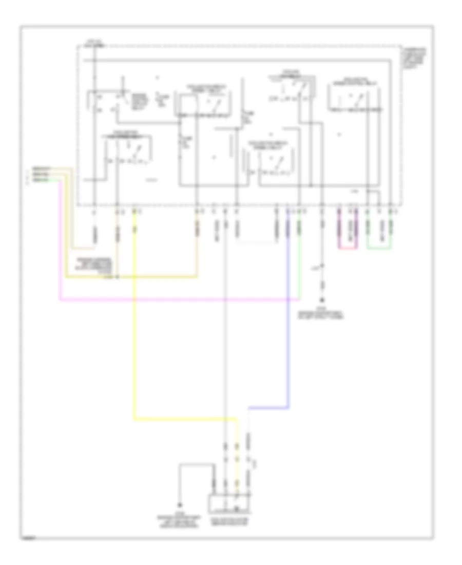
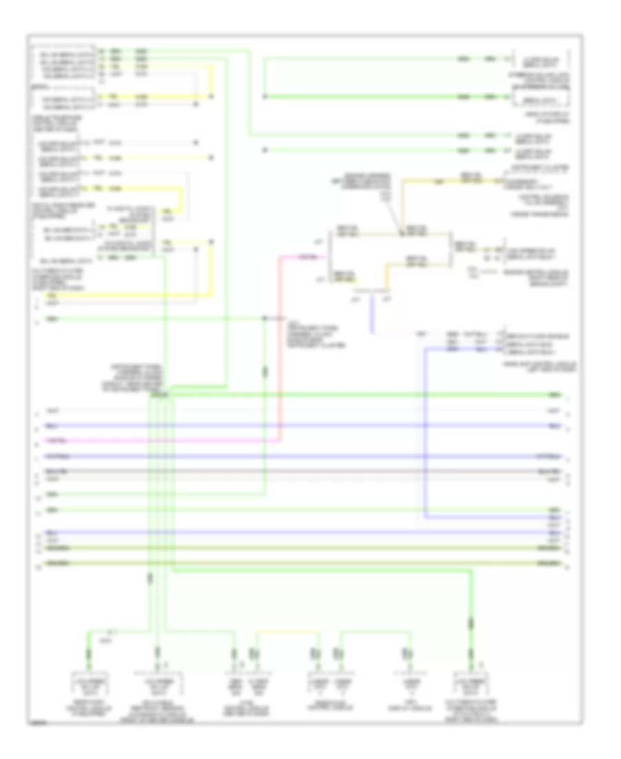
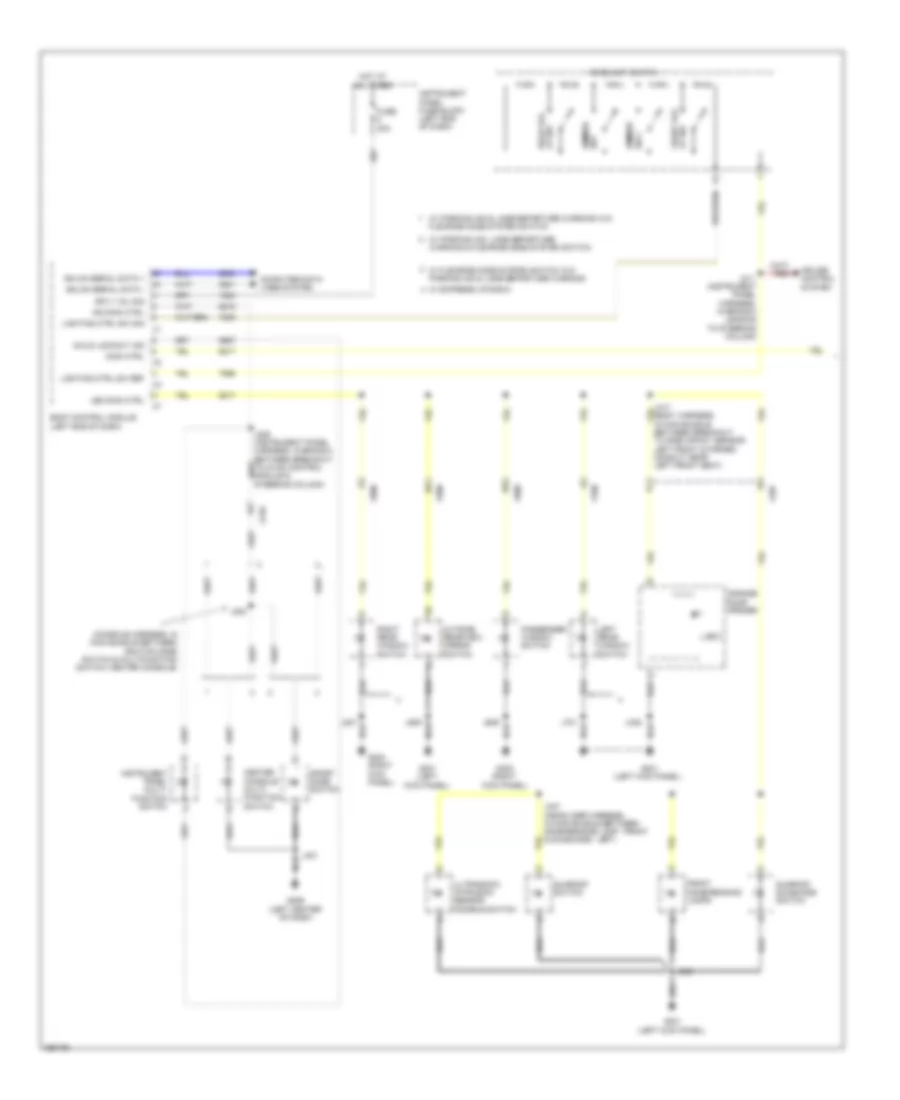
AIR CONDITIONING
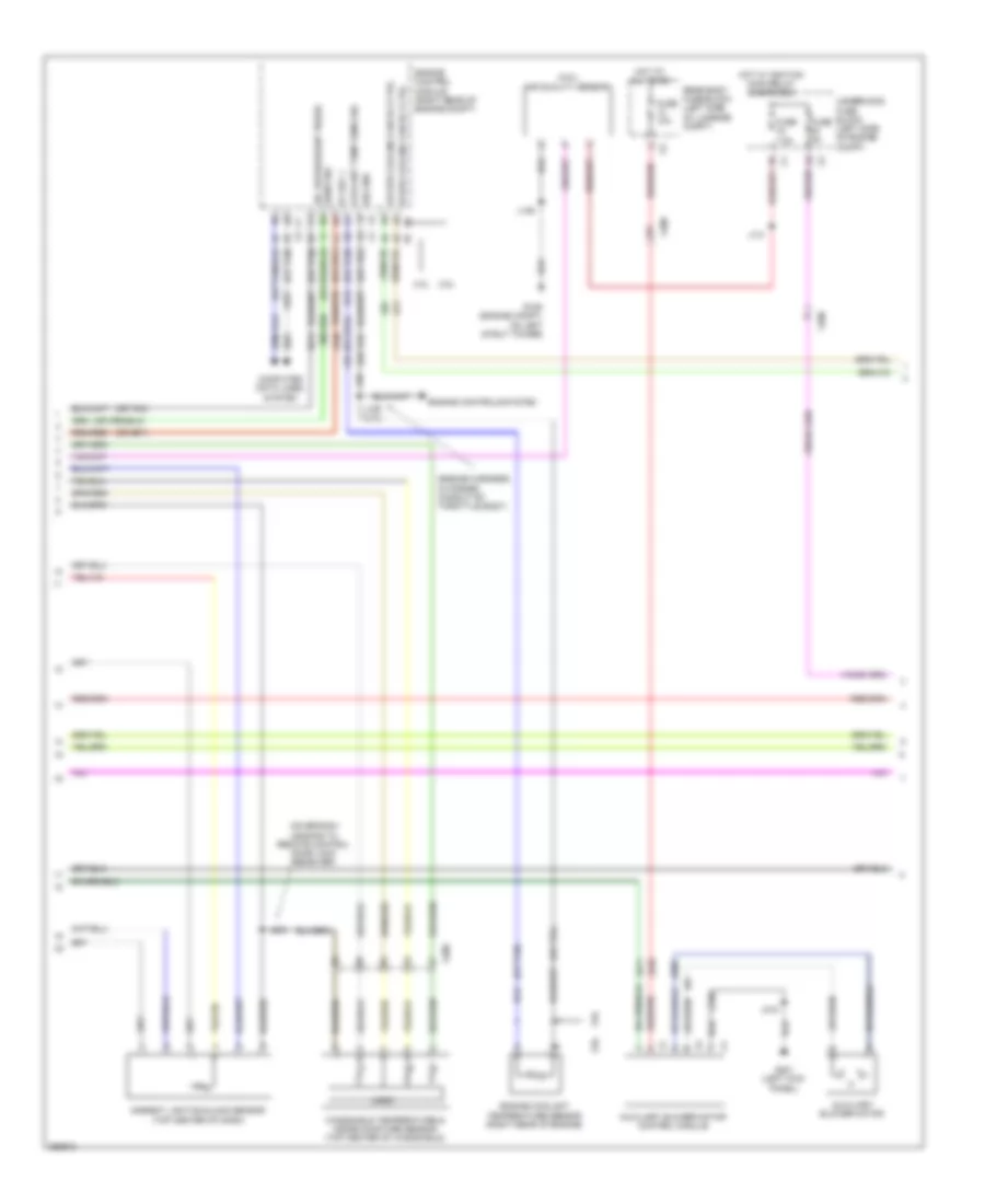
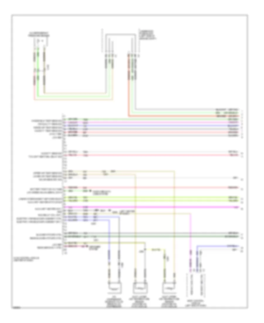
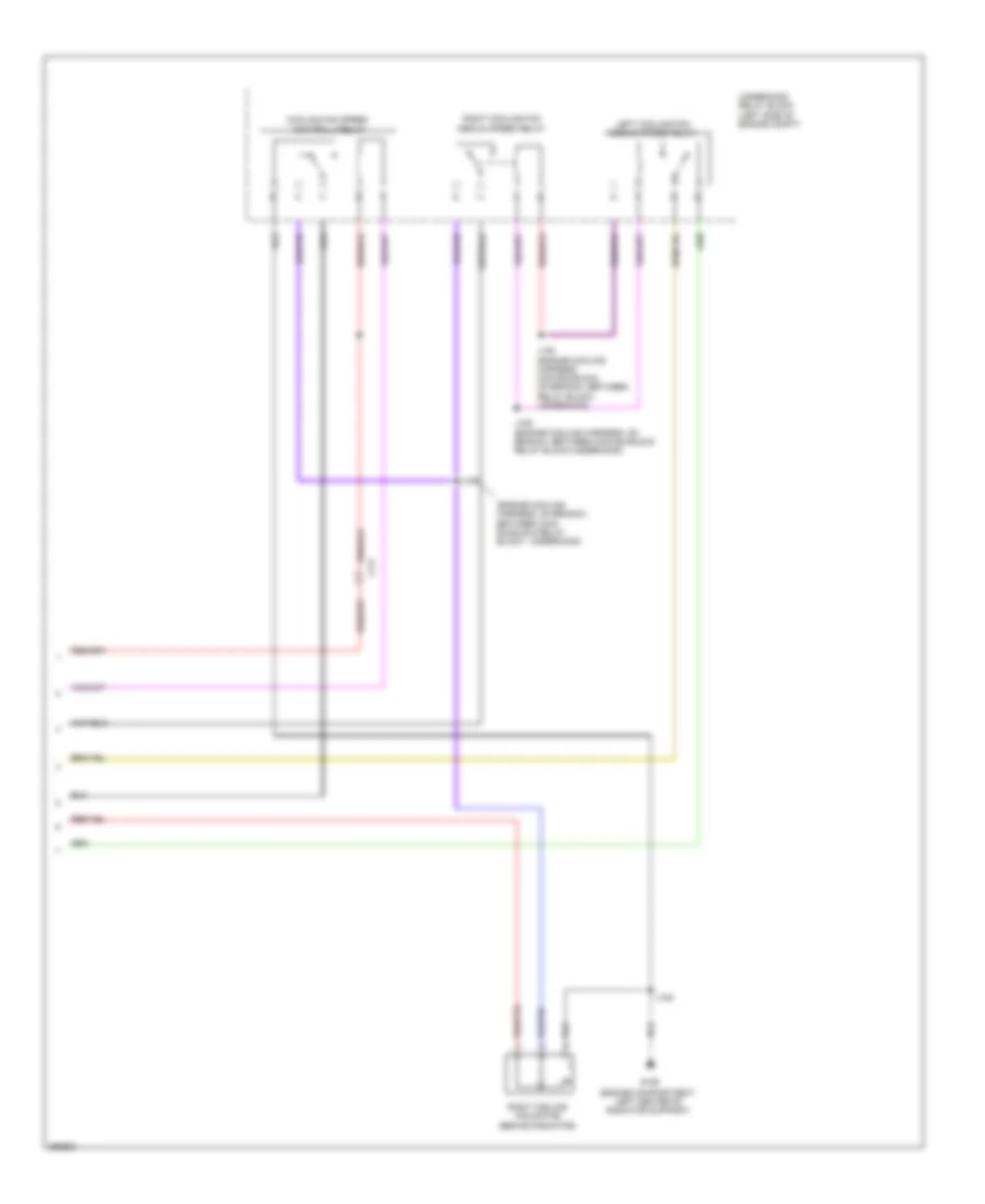
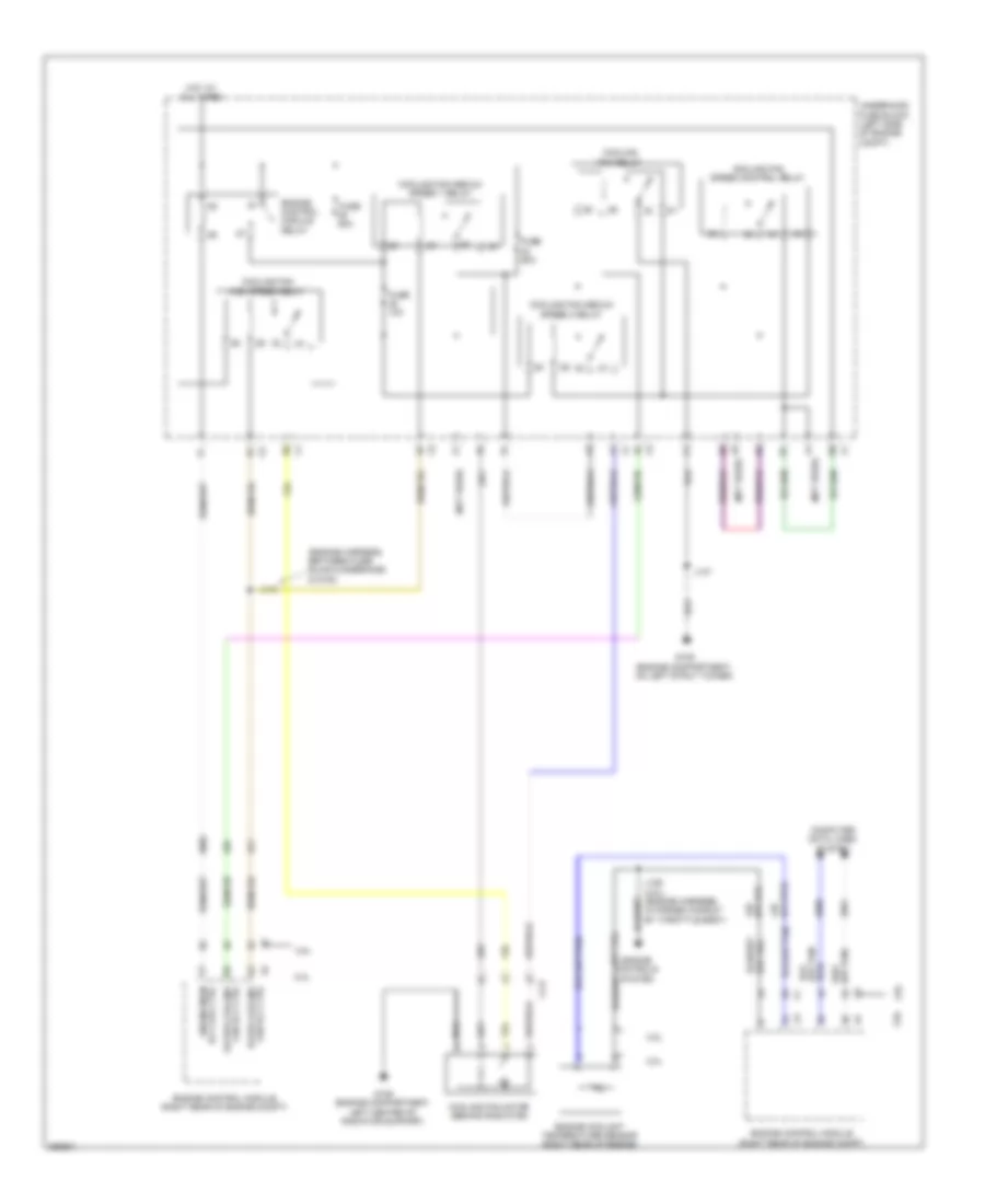
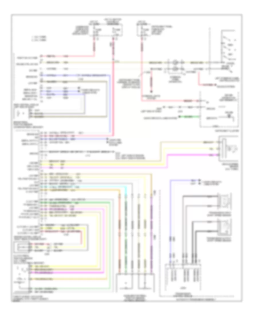
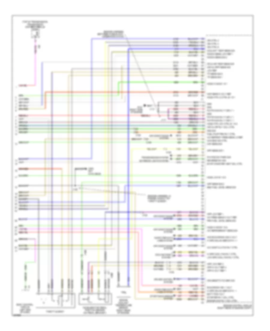
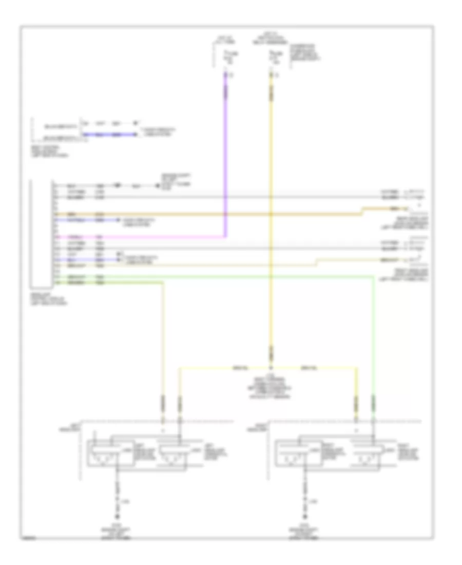
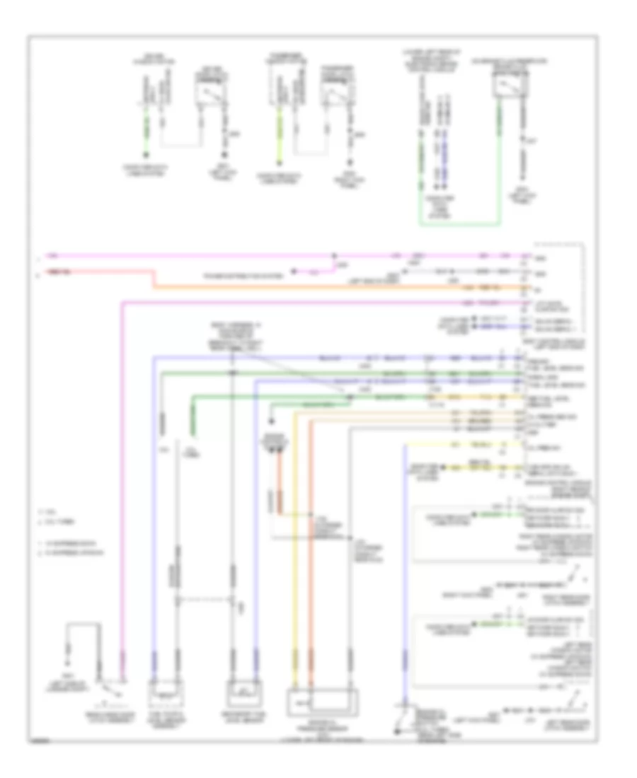
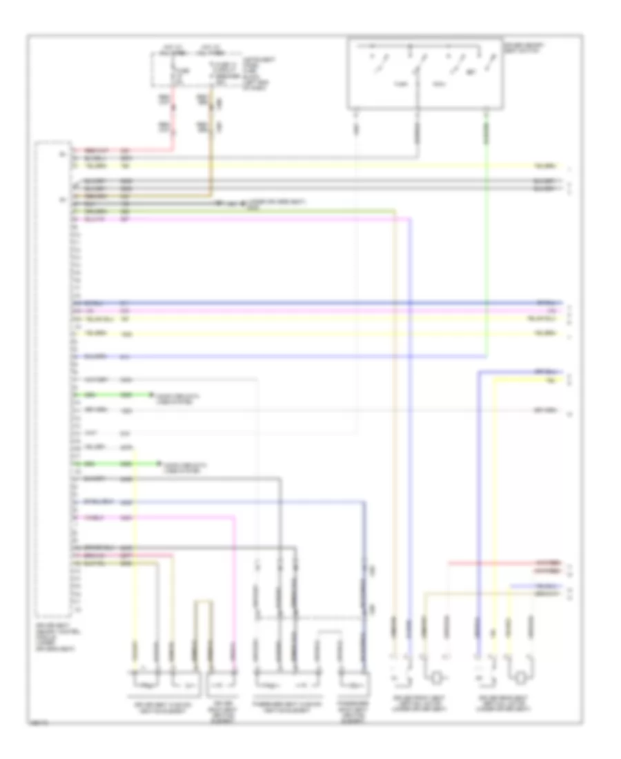
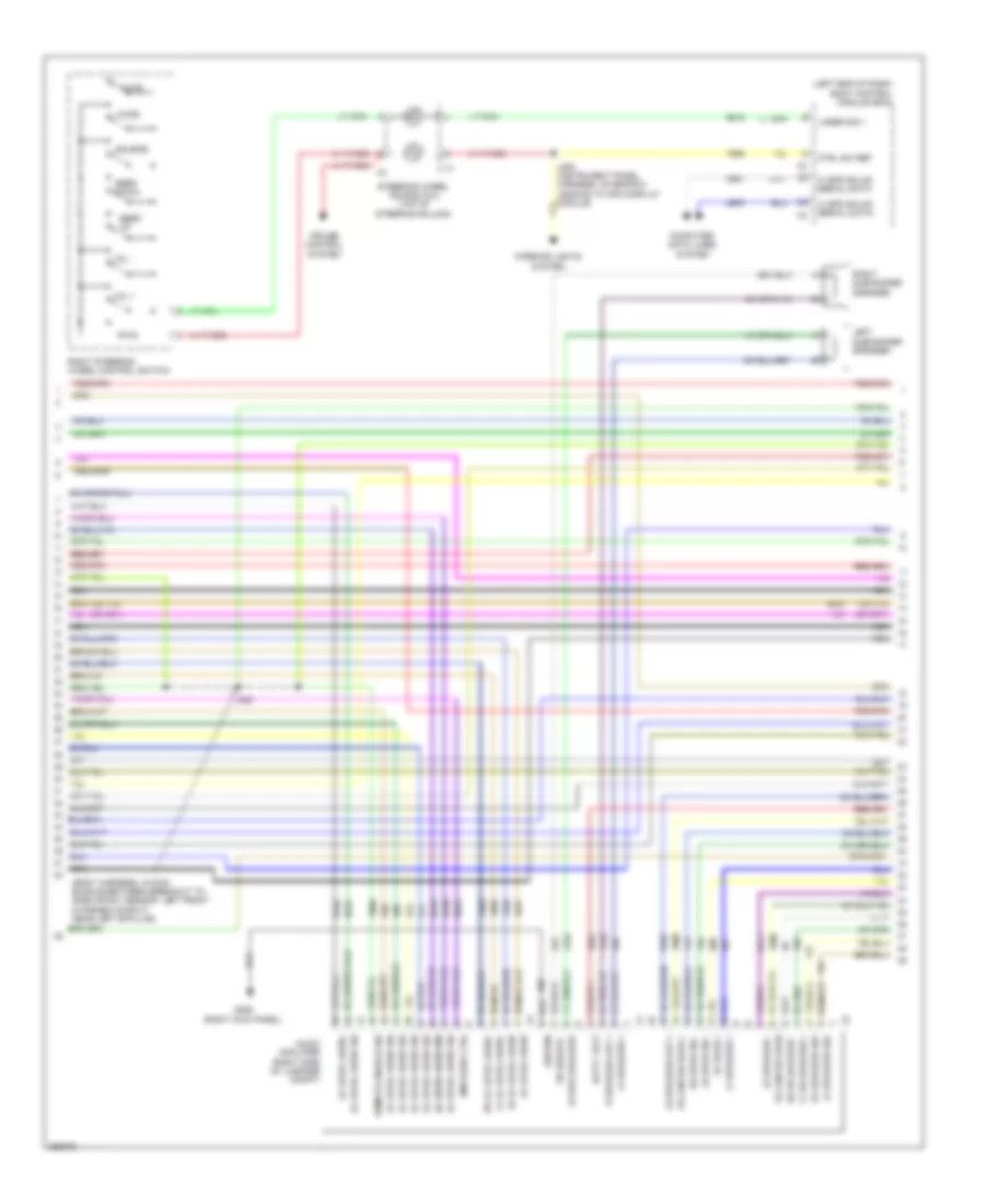
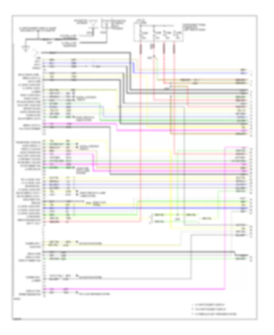
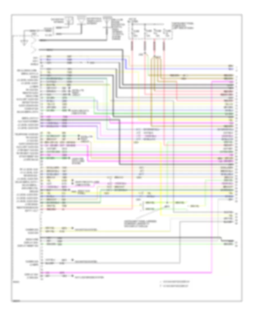
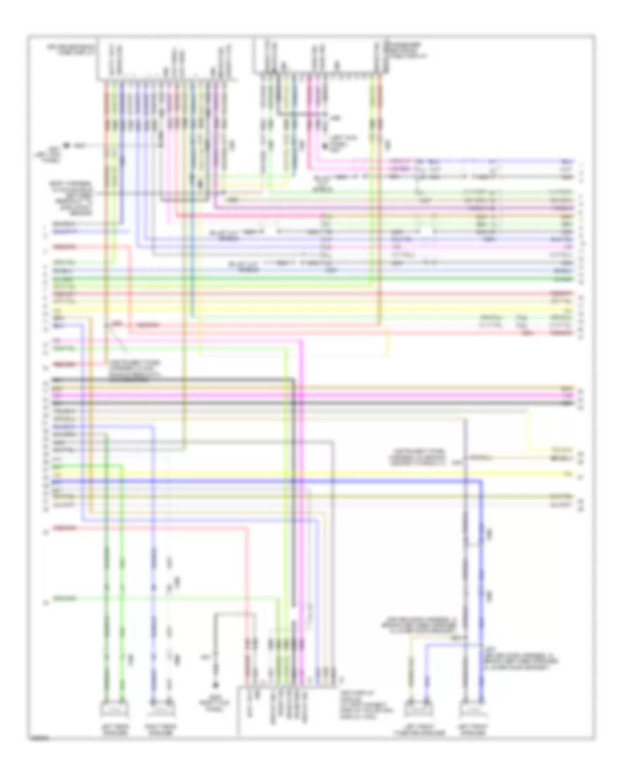
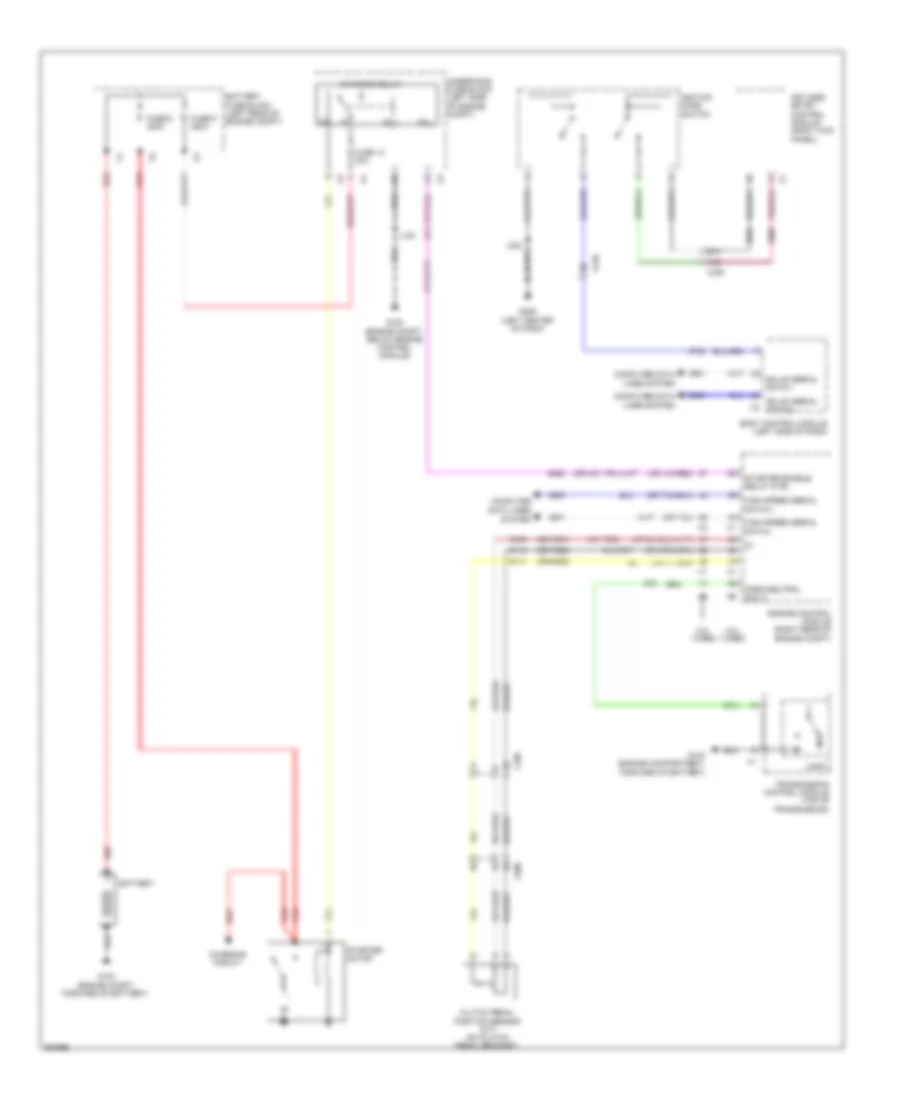
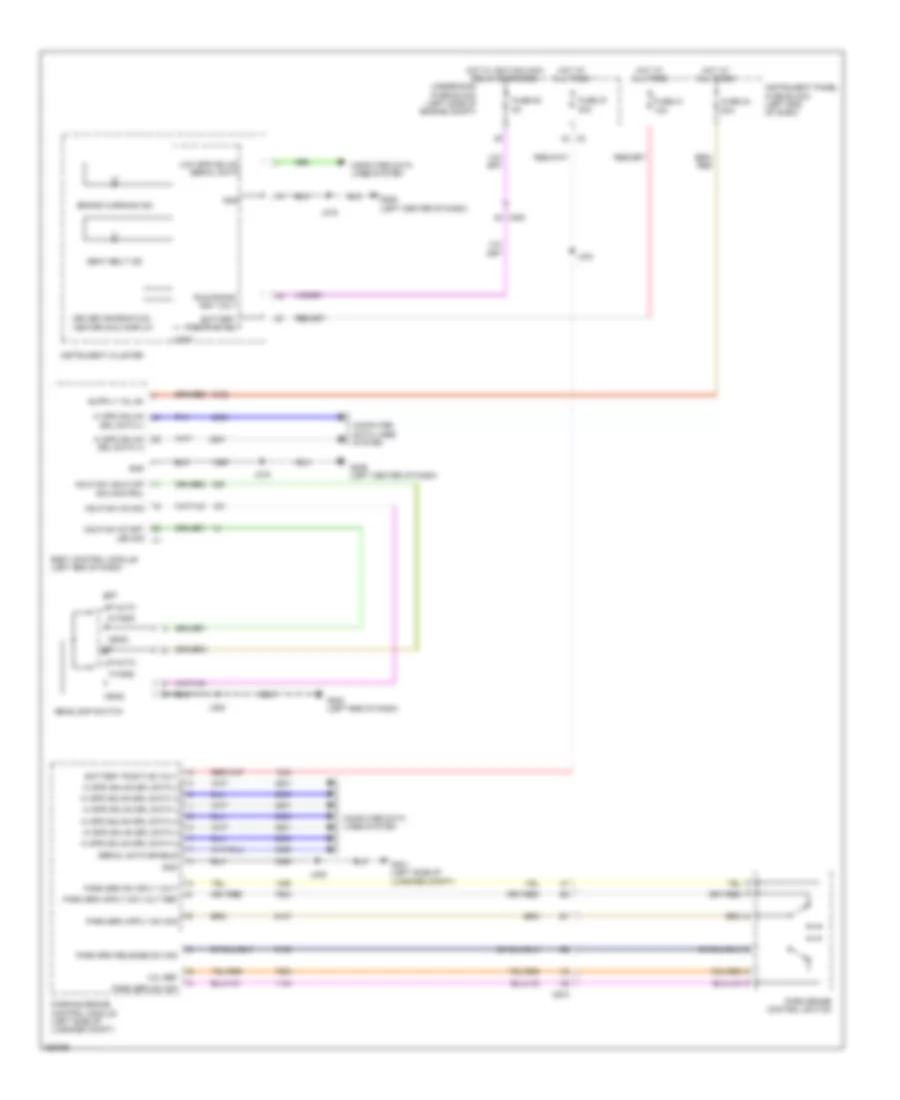
Automatic A/C Wiring Diagram, Dual Fans (1 of 6) for Saab 9-5 Aero 2011
 https://portal-diagnostov.com/license.html
Automotive Electricians Portal FZCO
Automotive Electricians Portal FZCO
https://portal-diagnostov.com/license.html
https://portal-diagnostov.com/license.html
Automotive Electricians Portal FZCO
Automotive Electricians Portal FZCO
List of elements for Automatic A/C Wiring Diagram, Dual Fans (1 of 6) for Saab 9-5 Aero 2011:
- (left center of dash)
- (or tan)
- 5-volt ref
- A/c compressor solenoid valve (rear of a/c compressor)
- A/c refrigerant pressure sensor
- Air quality sens sig
- Auxiliary heater cntl
- Auxiliary heater status sig
- Battery positive voltage
- Blower mtr spd ctrl
- Body control module (left end of dash)
- Computer data lines system
- Defogger system
- Duct lower air temperature sensor (mounted on hvac module)
- Duct upper air temperature sensor (mounted on hvac module)
- Electric variable displacement ctrl
- Electric variable displacement sply
- G206
- Gnd
- Humidity sens sig
- Humidity temp sens sig
- Hvac control module (center of dash)
- Inside air temp sens sig
- J299
- Linear interconnect network bus 9
- Low ref
- Low speed gmlan serial data
- Lower air temp sens sig
- Rear blower mtr spd ctrl
- Rear defog rly ctrl
- Run relay coil cntl
- Run rly coil ctrl
- Security ind ctrl
- Solar sens drv sig
- Twilight sentinel delay sig
- Underhood fuse block (left side of engine compt)
- Upper air temp sens sig
- Windshield temp sens sig
- X108
- X118
- X200
- X201
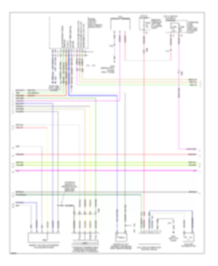
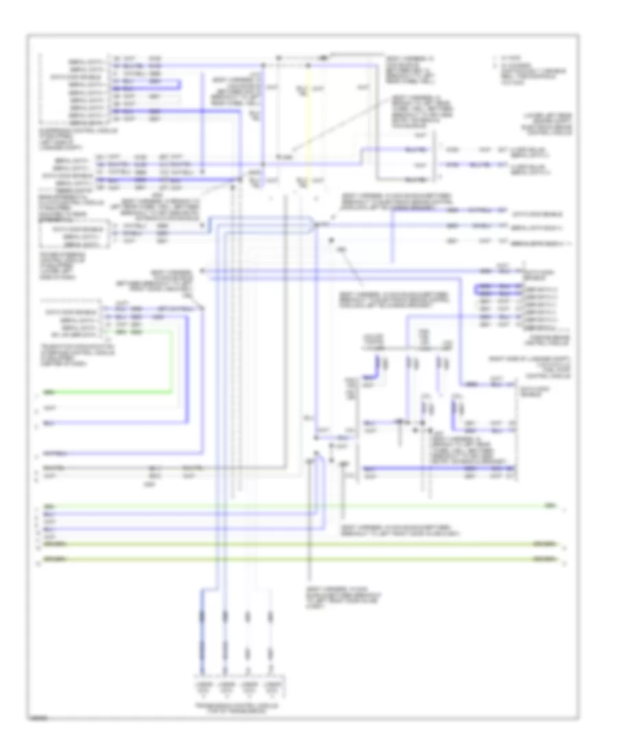
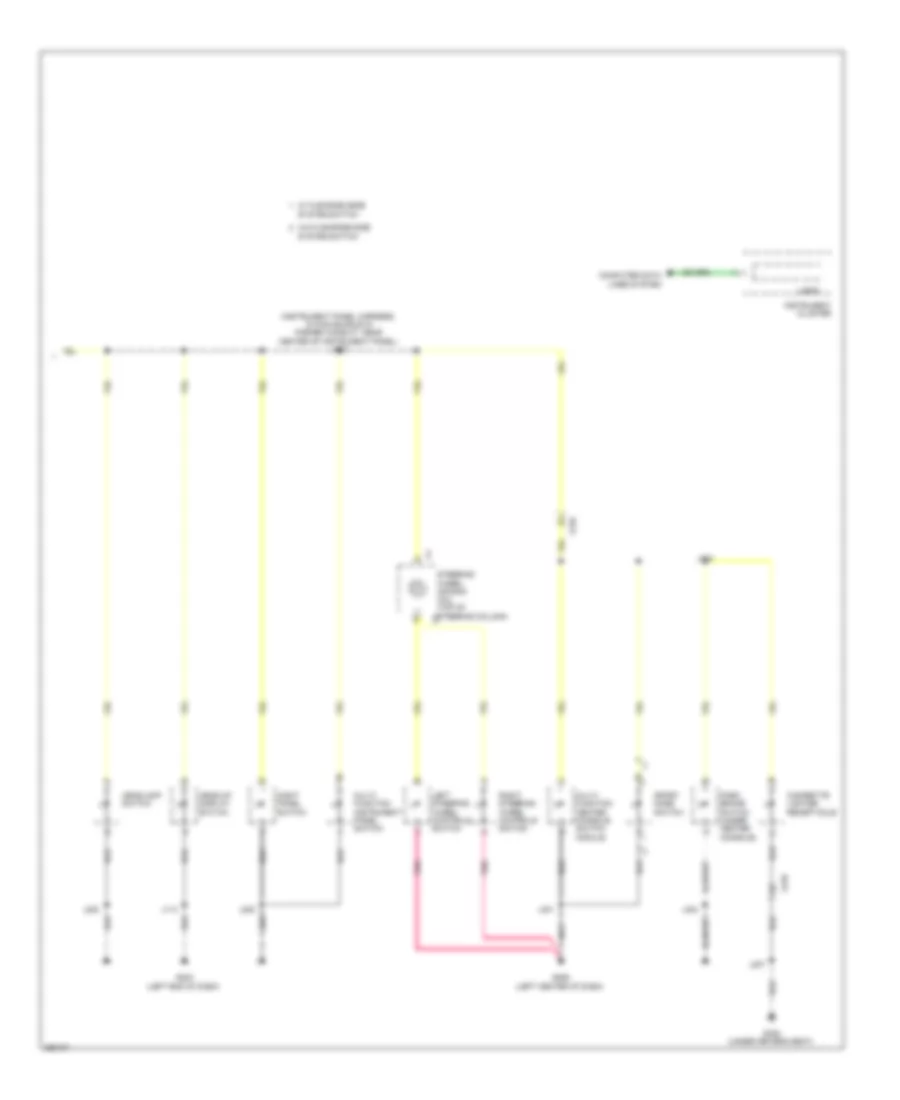
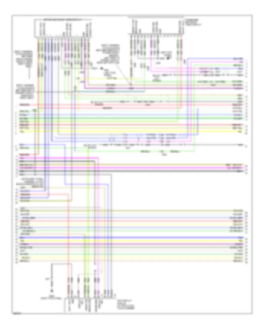
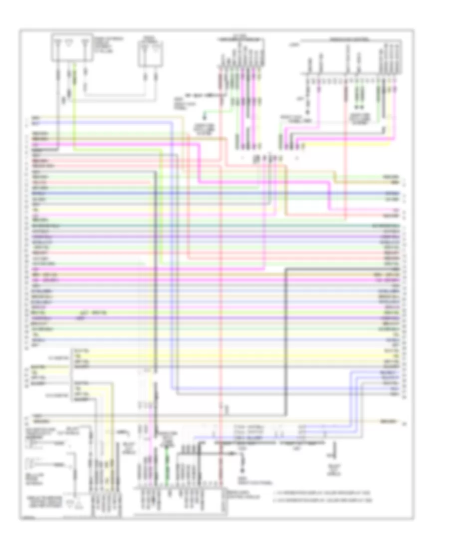
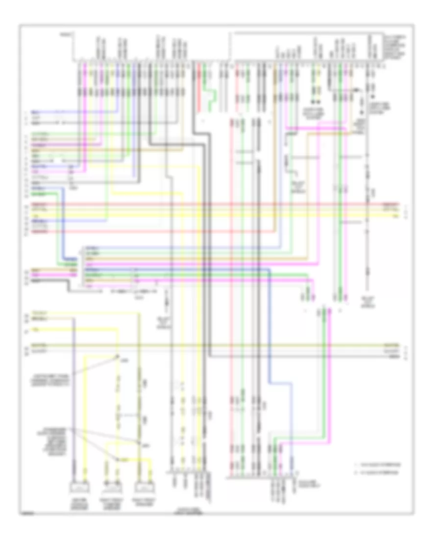
Automatic A/C Wiring Diagram, Dual Fans (2 of 6) for Saab 9-5 Aero 2011
List of elements for Automatic A/C Wiring Diagram, Dual Fans (2 of 6) for Saab 9-5 Aero 2011:
- (2.8l) air quality sensor
- (engine harness, in formed conduit by throttle body)
- (on branch leading to remote control door lock receiver)
- (or 151)
- (or 2761)
- (or tan)
- 2.0l
- 2.8l
- 5v ref 1
- A/c refrigerant press
- Ambient light/sunload sensor (top center of dash)
- Auxiliary blower motor
- Auxiliary blower motor control module
- Computer data lines system
- Coolant temp sens sig
- Engine control module (right rear of engine compt)
- Engine controls system
- Engine coolant temperature sensor (right rear of engine)
- Fuse 10a
- Fuse 5a
- Fuse 7.5a
- G109 (engine compt, on left strut tower)
- G201 (left kick panel)
- Hi spd cooling fan rly ctrl
- Hot at all times
- Hot w/ ignition main relay energized
- J126 (2.8l)
- J131
- J136
- J204
- J318
- Logic
- Lw spd cooling fan rly ctrl
- Rear body fuse block (left side of luggage compt)
- Sens sig
- Sig gnd
- Underhood fuse block (left side of engine compt)
- Windshield temperature & inside moisture sensor (top center of windshield)
- X200
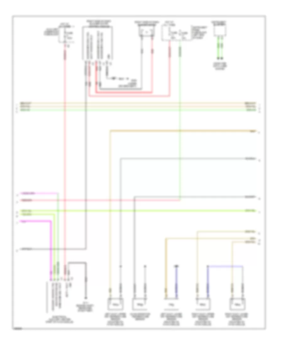
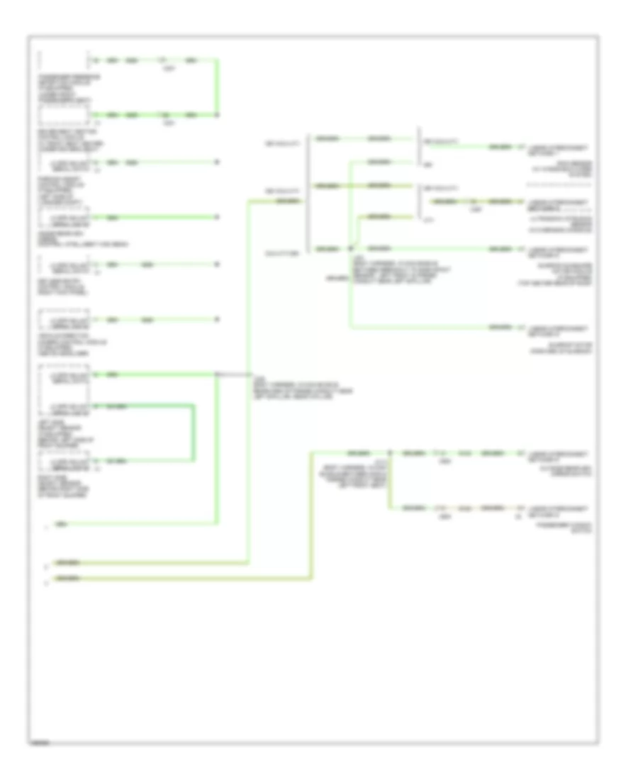
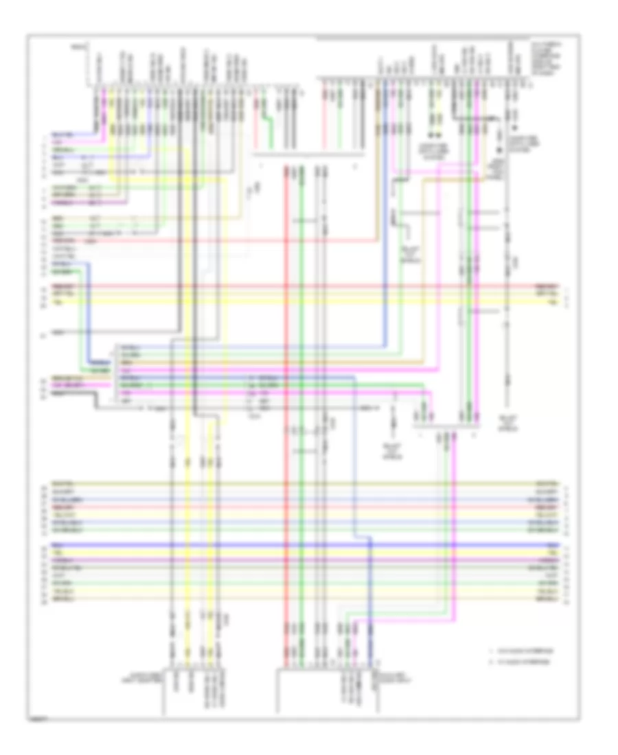
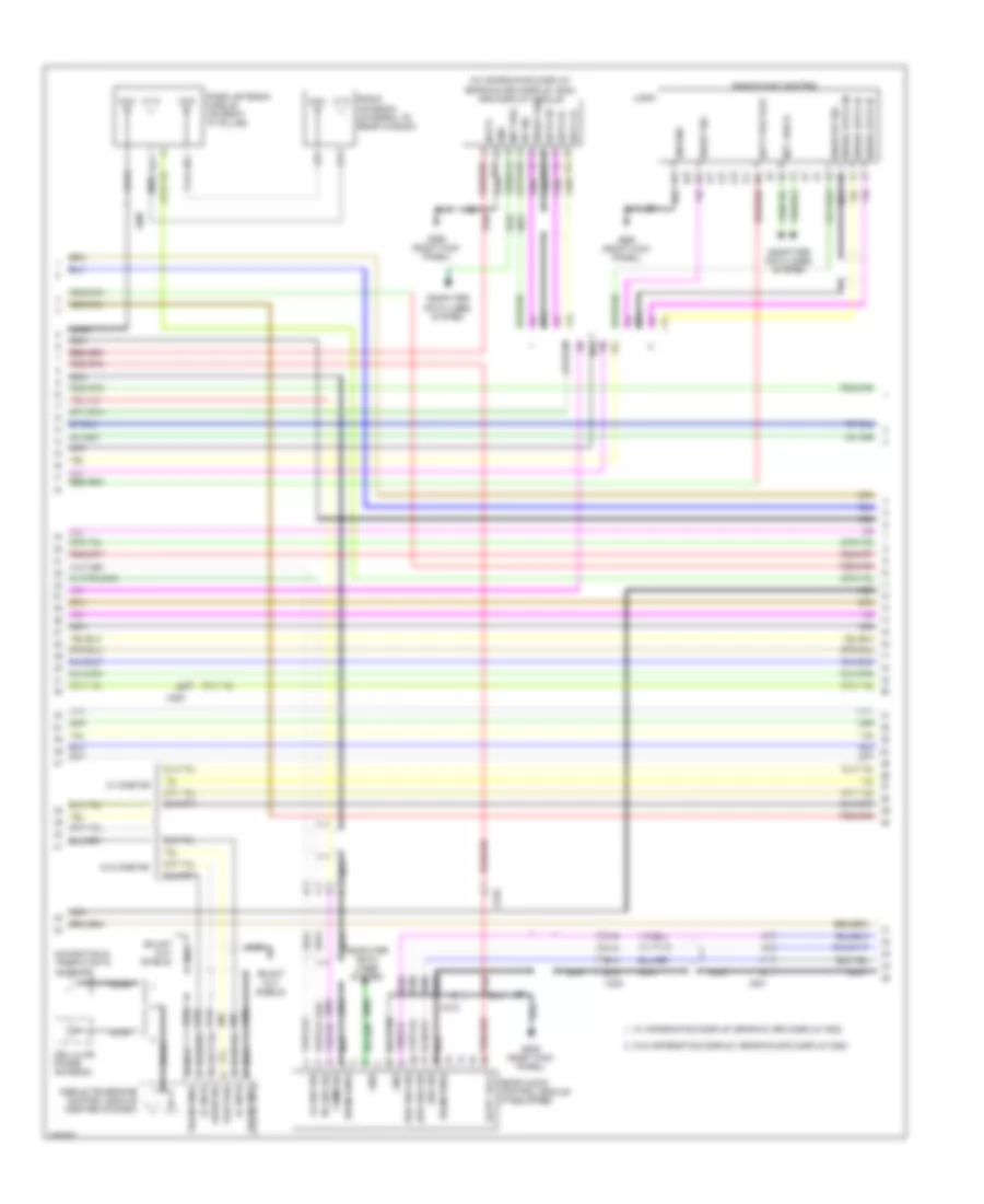
Automatic A/C Wiring Diagram, Dual Fans (3 of 6) for Saab 9-5 Aero 2011
List of elements for Automatic A/C Wiring Diagram, Dual Fans (3 of 6) for Saab 9-5 Aero 2011:
- (right side of dash) blower motor
- (right side of dash) blower motor control module
- (under driver's seat)
- A/c evaporator temperature sensor
- Auxiliary heater ctrl
- Auxiliary underhood fuse block
- Batt + volt
- Batt positive volt
- Blower mtr fan ctrl
- Blower mtr spd ctrl
- Blower mtr sply volt
- Computer data lines system
- Electrical auxiliary heater (part of hvac module)
- Fuse 100a
- Fuse 10a
- Fuse 50a
- G111 (engine compt, rearward of battery)
- G305
- Gnd
- Heater status sig
- Hot at all times
- Instrument cluster
- Instrument panel fuse block (left end of dash)
- J207
- J298
- Left duct lower air temperature sensor (mounted on hvac module)
- Left duct upper air temperature sensor (mounted on hvac module)
- Red
- Right duct lower air temperature sensor (mounted on hvac module)
- Right duct upper air temperature sensor (mounted on hvac module)
- Run/crank ign 1 volt
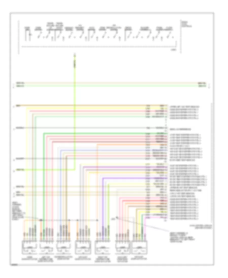
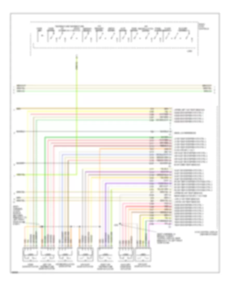
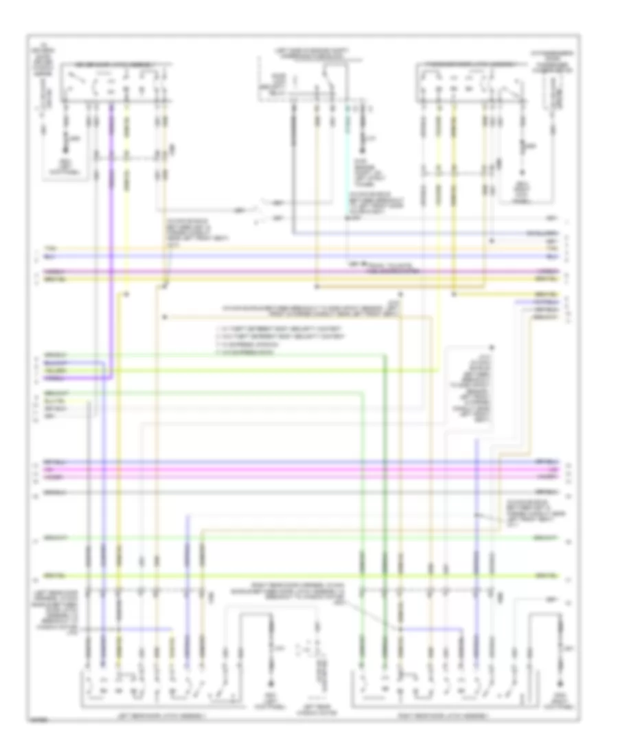
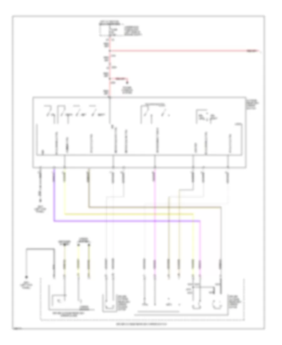
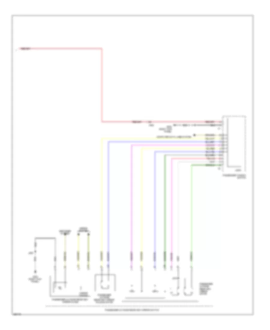
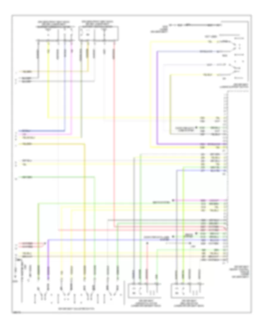
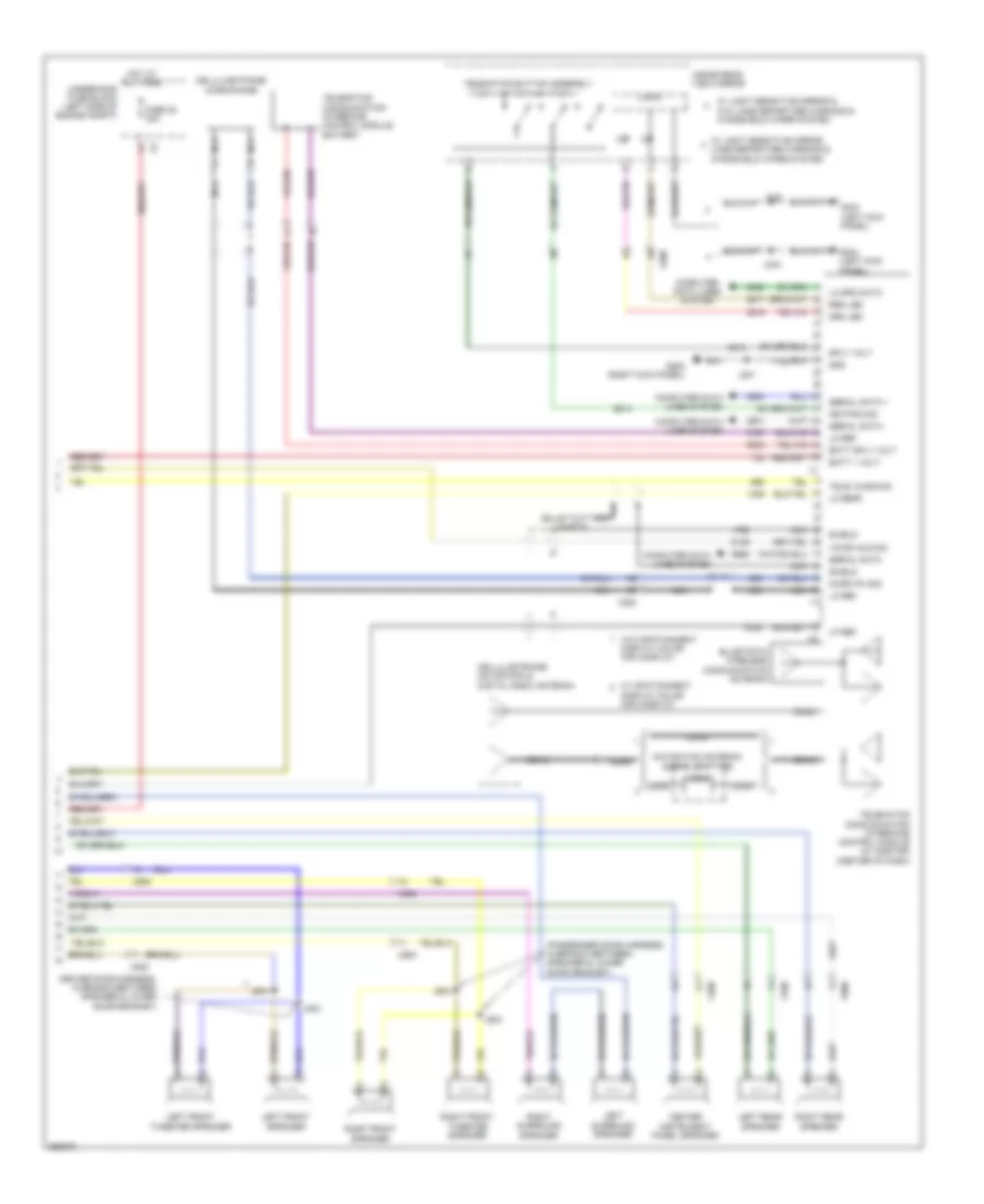
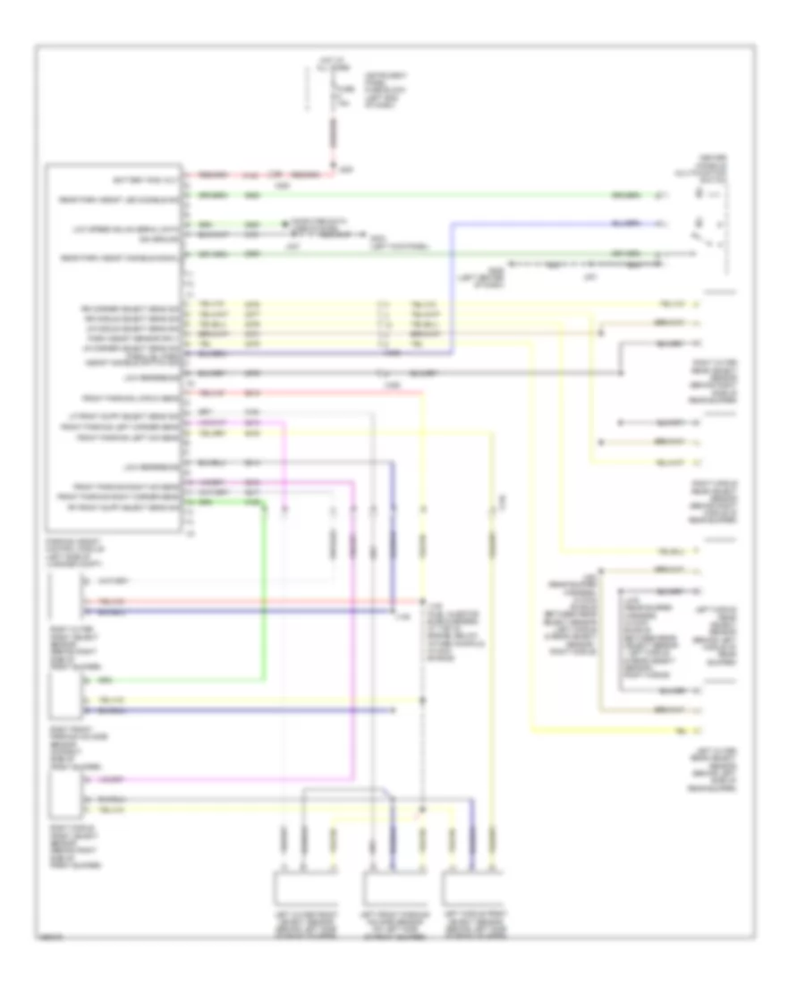
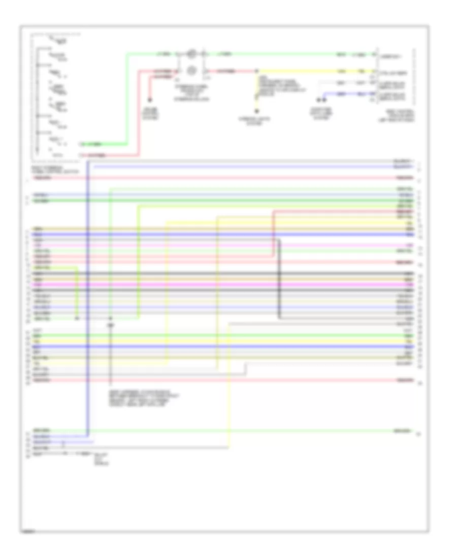
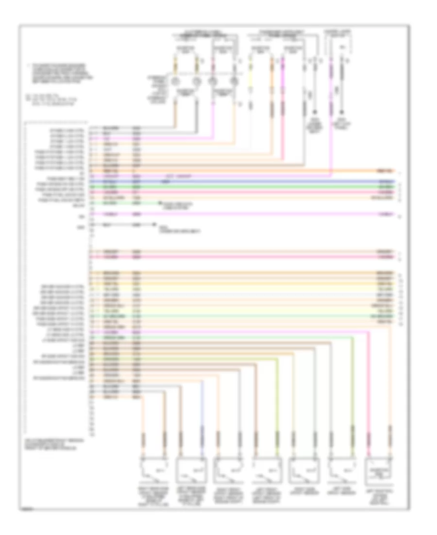
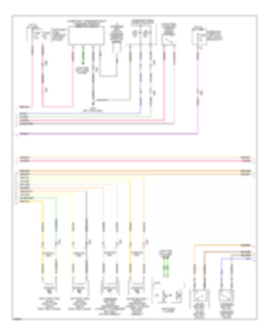
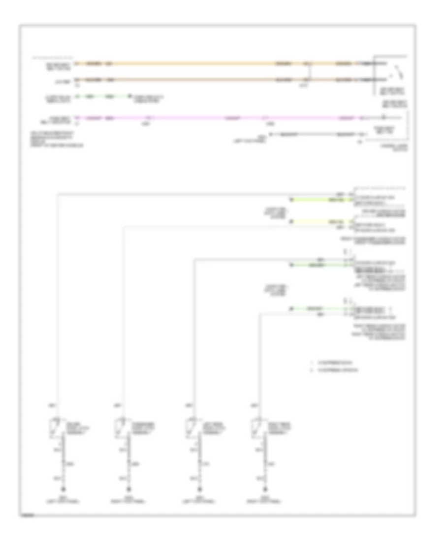
Automatic A/C Wiring Diagram, Dual Fans (4 of 6) for Saab 9-5 Aero 2011
List of elements for Automatic A/C Wiring Diagram, Dual Fans (4 of 6) for Saab 9-5 Aero 2011:
- (body harness, in branch to body control module, near breakout to left front door inline)
- (body harness, in main bundle between breakout to left front door inline & g201)
- A/c request switch
- Air inlet door actuator
- Air inlet dr stepper mtr ctrl 1
- Air inlet dr stepper mtr ctrl 2
- Air inlet dr stepper mtr ctrl 3
- Air inlet dr stepper mtr ctrl 4
- Air recirculation door motor
- Air recirculation switch
- Auto switch
- Auxiliary mode door actuator
- Blower switch
- Defog switch
- Defrost switch
- Evap core temp sens sig
- Floor switch
- Hvac control module (center of dash)
- Hvac mtr sply volt
- Inlet dr stepper mtr ctrl 1
- Inlet dr stepper mtr ctrl 2
- Inlet dr stepper mtr ctrl 3
- Inlet dr stepper mtr ctrl 4
- J232
- J233
- Left air temperature door actuator
- Lf dr temp stepper mtr ctrl 1
- Lf dr temp stepper mtr ctrl 2
- Lf dr temp stepper mtr ctrl 3
- Lf dr temp stepper mtr ctrl 4
- Logic
- Lwr lf air temp sens sig
- Lwr rh air temp sens sig
- Mode door actuator
- Mode dr stepper mtr ctrl 1
- Mode dr stepper mtr ctrl 2
- Mode dr stepper mtr ctrl 3
- Mode dr stepper mtr ctrl 4
- Mode ind
- Mode switch
- Panel switch
- Pnk
- Radio/ hvac controls
- Rear mode motor sply voltage
- Red
- Rh dr temp stepper mtr pass ctrl 1
- Rh dr temp stepper mtr pass ctrl 2
- Rh dr temp stepper mtr pass ctrl 3
- Rh dr temp stepper mtr pass ctrl 4
- Right air temperature door actuator
- Sens low reference
- Temp dr stepper mtr ctrl 1
- Temp dr stepper mtr ctrl 2
- Temp dr stepper mtr ctrl 3
- Temp dr stepper mtr ctrl 4
- Tempe- rature down switch
- Tempe- rature up switch
- Upper left air temp sens sig
- Upper rh air temp sens sig
- Zone switch
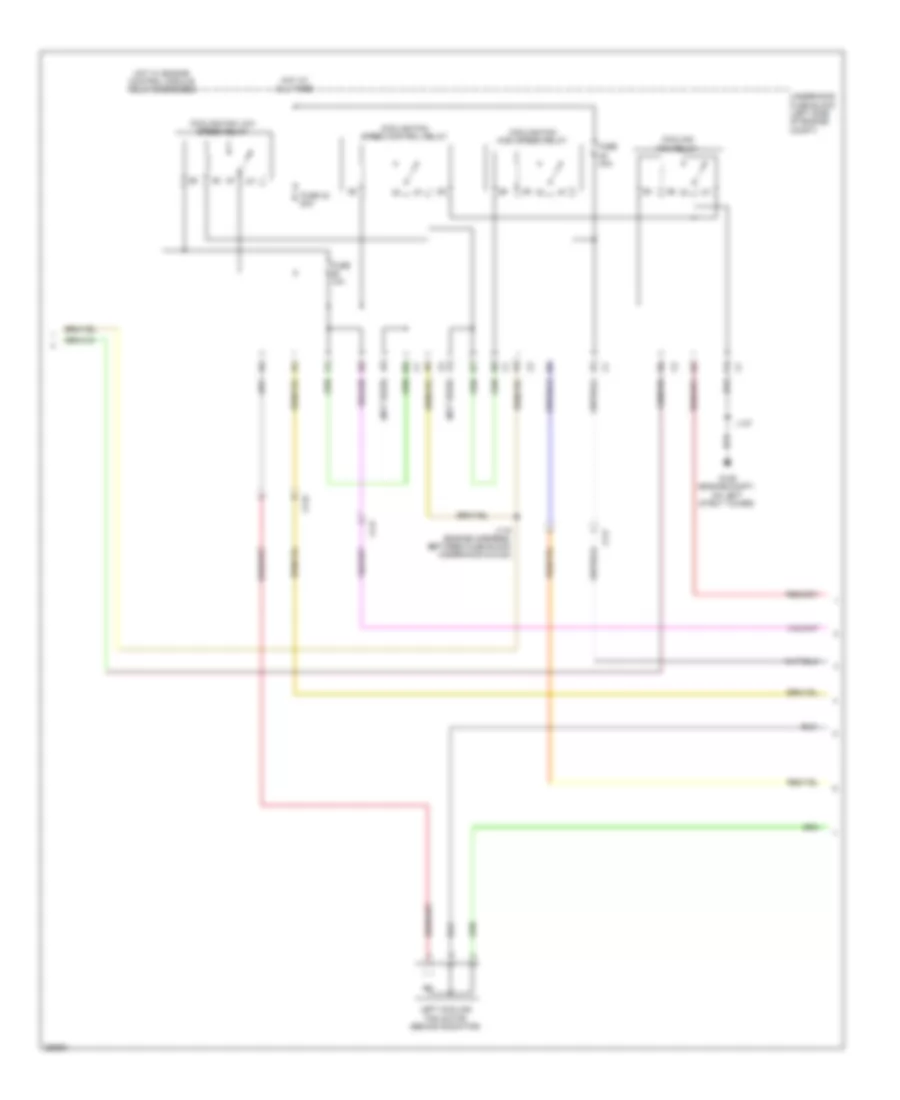
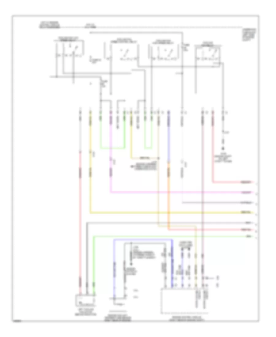
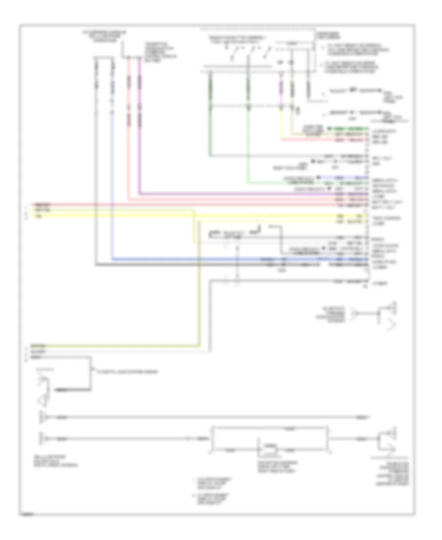
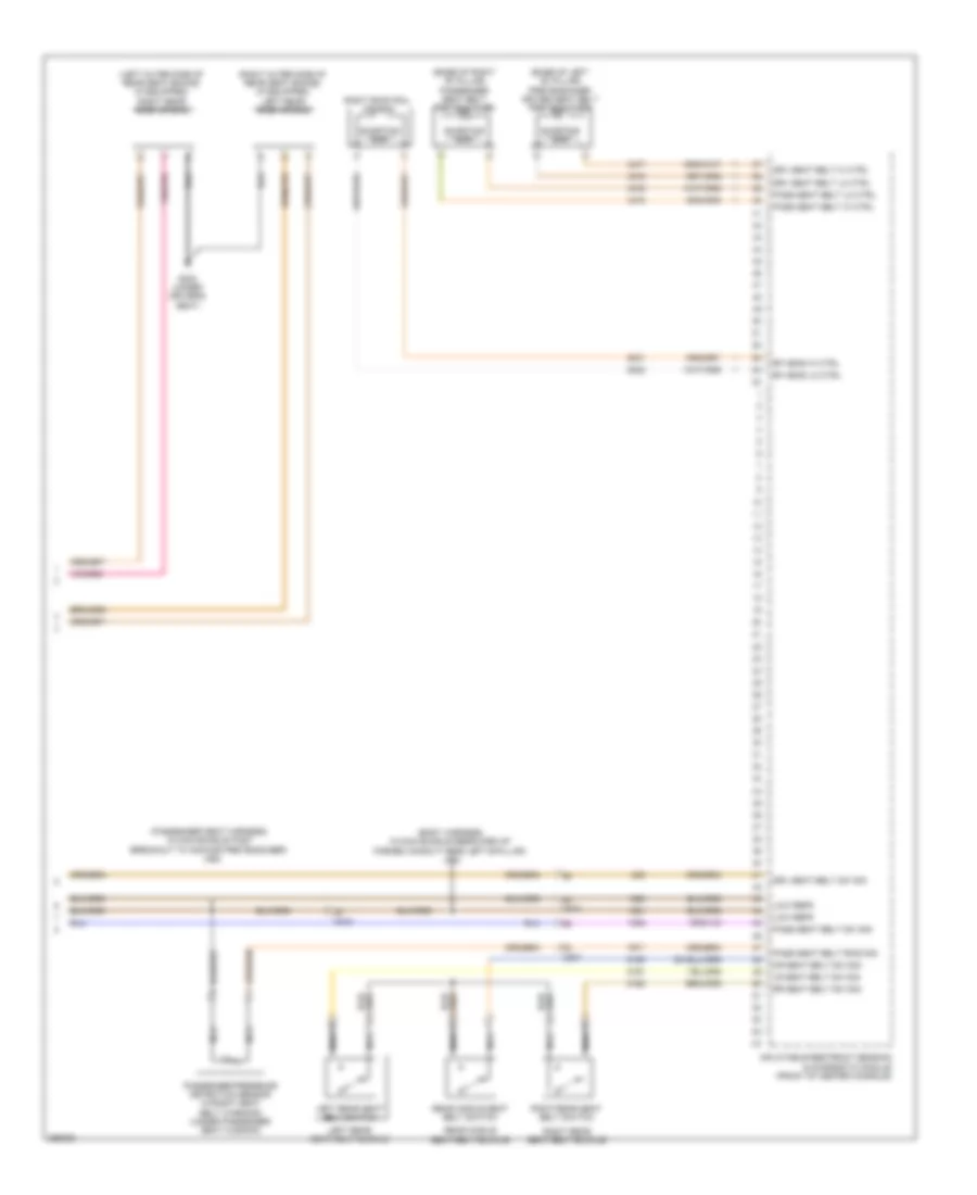
Automatic A/C Wiring Diagram, Dual Fans (5 of 6) for Saab 9-5 Aero 2011
List of elements for Automatic A/C Wiring Diagram, Dual Fans (5 of 6) for Saab 9-5 Aero 2011:
- (not used)
- Cooling fan high speed relay
- Cooling fan low speed relay
- Cooling fan relay
- Cooling fan speed control relay
- Fuse 10a
- Fuse 30a
- Fuse 42 20a
- G109 (engine compt, on left strut tower)
- Hot at all times
- Hot w/ engine control module relay energized
- J115 (engine harness, between fuse block underhood & g120)
- J137
- Left cooling fan motor (behind radiator)
- Underhood fuse block (left side of engine compt)
- X117
- X119
- X3 (not used)
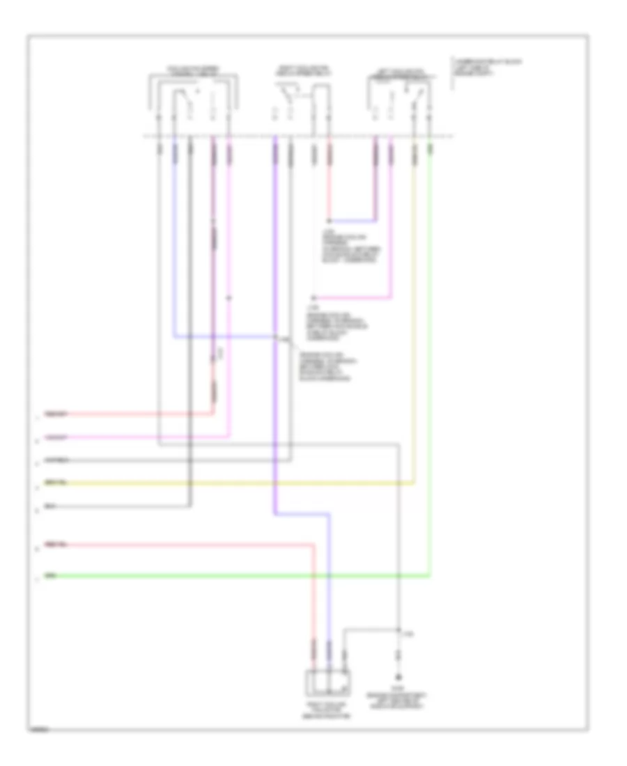
Automatic A/C Wiring Diagram, Dual Fans (6 of 6) for Saab 9-5 Aero 2011
List of elements for Automatic A/C Wiring Diagram, Dual Fans (6 of 6) for Saab 9-5 Aero 2011:
- (engine compartment, left center of radiator support)
- (engine cooling harness, on branch, between main bundle & relay block- underhood)
- (engine cooling harness, on branch, between main bundle & relay block-underhood)
- Cooling fan speed control 2 relay
- G106
- J105 (engine cooling harness, on branch, between main bundle & relay block - underhood)
- J106
- J107
- J108
- Left cooling fan medium speed relay
- Right cooling fan medium speed relay
- Right cooling fan motor (behind radiator)
- Underhood relay block (left side of engine compt)
- X117
Automatic A/C Wiring Diagram, Single Fan (1 of 5) for Saab 9-5 Aero 2011
List of elements for Automatic A/C Wiring Diagram, Single Fan (1 of 5) for Saab 9-5 Aero 2011:
- (left center of dash)
- (or tan)
- 5-volt ref
- A/c compressor solenoid valve (rear of a/c compressor)
- A/c refrigerant pressure sensor
- Air quality sens sig
- Auxiliary heater cntl
- Auxiliary heater status sig
- Battery positive voltage
- Blower mtr spd ctrl
- Body control module (left end of dash)
- Computer data lines system
- Defogger system
- Duct lower air temperature sensor (mounted on hvac module)
- Duct upper air temperature sensor (mounted on hvac module)
- Electric variable displacement ctrl
- Electric variable displacement sply
- G206
- Gnd
- Humidity sens sig
- Humidity temp sens sig
- Hvac control module (center of dash)
- Inside air temp sens sig
- J299
- Linear interconnect network bus 9
- Low ref
- Low speed gmlan serial data
- Lower air temp sens sig
- Rear blower mtr spd ctrl
- Rear defog rly ctrl
- Run relay coil cntl
- Run rly coil ctrl
- Security ind ctrl
- Solar sens drv sig
- Twilight sentinel delay sig
- Underhood fuse block (left side of engine compt)
- Upper air temp sens sig
- Windshield temp sens sig
- X108
- X118
- X200
- X201
Automatic A/C Wiring Diagram, Single Fan (2 of 5) for Saab 9-5 Aero 2011
List of elements for Automatic A/C Wiring Diagram, Single Fan (2 of 5) for Saab 9-5 Aero 2011:
- (2.8l) air quality sensor
- (on branch leading to remote control door lock receiver)
- (or 151)
- (or 2761)
- (or tan)
- 2.0l
- 2.8l
- 5v ref 1
- A/c refrigerant press
- Ambient light/sunload sensor (top center of dash)
- Auxiliary blower motor
- Auxiliary blower motor control module
- Computer data lines system
- Coolant temp sens sig
- Engine control module (right rear of engine compt)
- Engine coolant temperature sensor (right rear of engine)
- Engine main rly coil ctrl
- Fuse 10a
- Fuse 5a
- Fuse 7.5a
- G109 (engine compt, on left strut tower)
- G201 (left kick panel)
- Hi spd cooling fan rly ctrl
- Hot at all times
- Hot w/ ignition main relay energized
- J131
- J136
- J204
- J318
- Logic
- Lw spd cooling fan rly ctrl
- Rear body fuse block (left side of luggage compt)
- Sens sig
- Sig gnd
- Underhood fuse block (left side of engine compt)
- Windshield temperature & inside moisture sensor (top center of windshield)
- X200
Automatic A/C Wiring Diagram, Single Fan (3 of 5) for Saab 9-5 Aero 2011
List of elements for Automatic A/C Wiring Diagram, Single Fan (3 of 5) for Saab 9-5 Aero 2011:
- (right side of dash) blower motor
- (right side of dash) blower motor control module
- (under driver's seat)
- A/c evaporator temperature sensor
- Auxiliary heater ctrl
- Auxiliary underhood fuse block
- Batt + volt
- Batt positive volt
- Blower mtr fan ctrl
- Blower mtr spd ctrl
- Blower mtr sply volt
- Computer data lines system
- Electrical auxiliary heater (part of hvac module)
- Fuse 100a
- Fuse 10a
- Fuse 50a
- G111 (engine compt, rearward of battery)
- G305
- Gnd
- Heater status sig
- Hot at all times
- Instrument cluster
- Instrument panel fuse block (left end of dash)
- J207
- J298
- Left duct lower air temperature sensor (mounted on hvac module)
- Left duct upper air temperature sensor (mounted on hvac module)
- Red
- Right duct lower air temperature sensor (mounted on hvac module)
- Right duct upper air temperature sensor (mounted on hvac module)
- Run/crank ign 1 volt
Automatic A/C Wiring Diagram, Single Fan (4 of 5) for Saab 9-5 Aero 2011
List of elements for Automatic A/C Wiring Diagram, Single Fan (4 of 5) for Saab 9-5 Aero 2011:
- (body harness, in branch to body control module, near breakout to left front door inline)
- (body harness, in main bundle between breakout to left front door inline & g201)
- A/c request switch
- Air inlet door actuator
- Air inlet dr stepper mtr ctrl 1
- Air inlet dr stepper mtr ctrl 2
- Air inlet dr stepper mtr ctrl 3
- Air inlet dr stepper mtr ctrl 4
- Air recirculation door motor
- Air recirculation switch
- Auto switch
- Auxiliary mode door actuator
- Blower switch
- Defog switch
- Defrost switch
- Evap core temp sens sig
- Floor switch
- Hvac control module (center of dash)
- Hvac mtr sply volt
- Inlet dr stepper mtr ctrl 1
- Inlet dr stepper mtr ctrl 2
- Inlet dr stepper mtr ctrl 3
- Inlet dr stepper mtr ctrl 4
- J232
- J233
- Left air temperature door actuator
- Lf dr temp stepper mtr ctrl 1
- Lf dr temp stepper mtr ctrl 2
- Lf dr temp stepper mtr ctrl 3
- Lf dr temp stepper mtr ctrl 4
- Logic
- Lwr lf air temp sens sig
- Lwr rh air temp sens sig
- Mode door actuator
- Mode dr stepper mtr ctrl 1
- Mode dr stepper mtr ctrl 2
- Mode dr stepper mtr ctrl 3
- Mode dr stepper mtr ctrl 4
- Mode ind
- Mode switch
- Panel switch
- Pnk
- Radio/ hvac controls
- Rear mode motor sply voltage
- Red
- Rh dr temp stepper mtr pass ctrl 1
- Rh dr temp stepper mtr pass ctrl 2
- Rh dr temp stepper mtr pass ctrl 3
- Rh dr temp stepper mtr pass ctrl 4
- Right air temperature door actuator
- Sens low reference
- Temp dr stepper mtr ctrl 1
- Temp dr stepper mtr ctrl 2
- Temp dr stepper mtr ctrl 3
- Temp dr stepper mtr ctrl 4
- Temperature down switch
- Temperature up switch
- Upper left air temp sens sig
- Upper rh air temp sens sig
- Zone switch
Automatic A/C Wiring Diagram, Single Fan (5 of 5) for Saab 9-5 Aero 2011
List of elements for Automatic A/C Wiring Diagram, Single Fan (5 of 5) for Saab 9-5 Aero 2011:
- (engine harness, between fuse block-underhood & g120)
- (not used)
- Cooling fan high speed relay
- Cooling fan medium speed 1 relay
- Cooling fan medium speed 2 relay
- Cooling fan motor (behind radiator)
- Cooling fan relay
- Cooling fan speed control relay
- Engine control module relay
- Fuse 10a
- Fuse 60a
- G106 (engine compartment, left center of radiator support)
- G109 (engine compartment, on left strut tower)
- Hot at all times
- J115
- J137
- Underhood fuse block (left side of engine compt)
- X117
ANTI-LOCK BRAKES
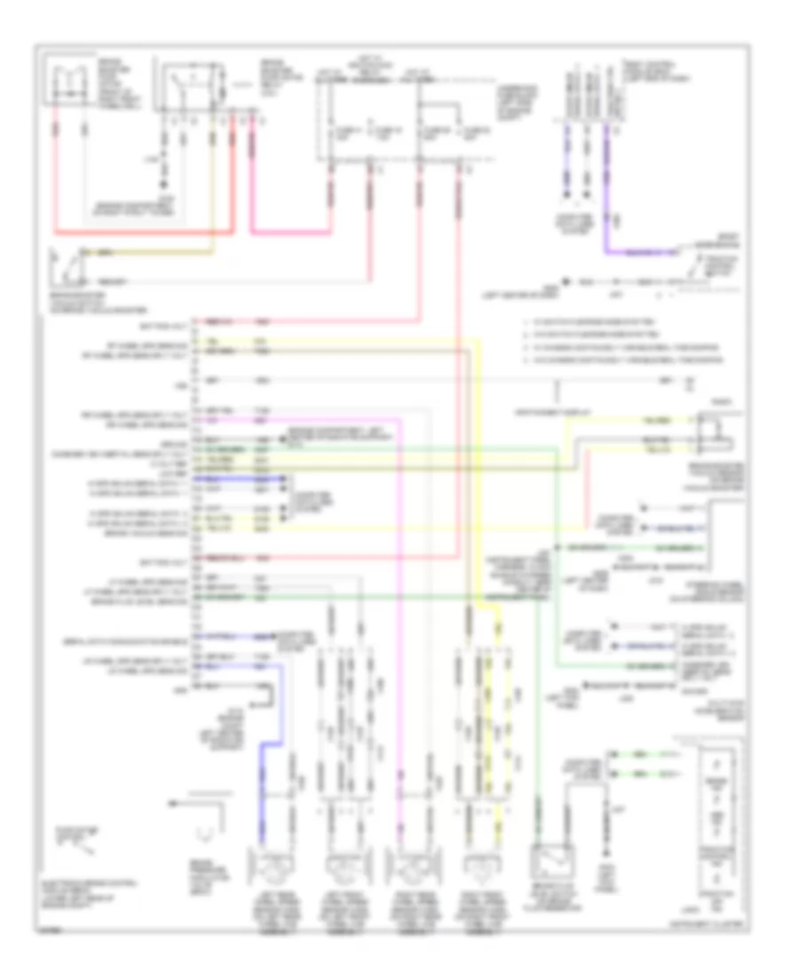
Anti-lock Brakes Wiring Diagram for Saab 9-5 Aero 2011
List of elements for Anti-lock Brakes Wiring Diagram for Saab 9-5 Aero 2011:
- (engine compartment, left center of radiator support) g110
- 5 volt ref
- Abs ind
- Bat pos volt
- Body control module (bcm) (left end of dash)
- Brake booster pump motor (front of right front wheelwell)
- Brake booster pump motor relay (2.8l)
- Brake booster vacuum sensor (on brake vacuum booster)
- Brake booster vacuum switch (on brake vacuum booster)
- Brake fluid level sens sig
- Brake fluid level switch (on brake fluid reservoir)
- Brake ind
- Brake pressure modulator valve (bpmv)
- Brake vacuum sens sig
- Combined veh inertial sens sply volt
- Computer data lines system
- Electronic brake control module (ebcm) (lower left rear of engine compt)
- Fuse 16 7.5a
- Fuse 22 50a
- Fuse 26 60a
- Fuse 41 30a
- G102 (engine compartment, on right strut tower)
- G110 (engine compt left center of radiator support)
- G206 (left center of dash)
- G304 (left kick panel)
- Gnd
- Ground
- Hi spd gmlan serial data + 1
- Hi spd gmlan serial data + 2
- Hi spd gmlan serial data - 1
- Hi spd gmlan serial data - 2
- Hot at all times
- Hot w/ ignition main relay energized
- Infotainment display
- Instrument cluster
- J135
- J215
- J221 (instrument panel harness, in main bundle in formed conduit, near center of instrument panel)
- J301
- J335
- J337
- Left front wheel speed sensor (wss) (on left front wheel hub assembly)
- Left rear wheel speed sensor (wss) (on left rear wheel hub assembly)
- Lf wheel spd sens sig
- Lf wheel spd sens sply volt
- Logic
- Low ref
- Lr wheel spd sens sig
- Lr wheel spd sens sply volt
- Multi-axis acceleration sensor
- Pump motor control
- Radio
- Red
- Rf wheel spd sens sig
- Rf wheel spd sens sply volt
- Right front wheel speed sensor (wss) (on right front wheel hub assembly)
- Right rear wheel speed sensor (wss) (on right rear wheel hub assembly)
- Rr wheel spd sens sig
- Rr wheel spd sens sply volt
- Serial data + 1 hi spd gmlan
- Serial data - 1 hi spd gmlan
- Serial data communication enable
- Sig gnd
- Sport mode switch
- Steering wheel angle sensor (on steering column)
- Traction control ind
- Traction control switch
- Traction ctrl sw sig 1
- Traction off ind
- Underhood fuse block (left side of engine compt)
- Vss
- W/ chassis continuosly variable real time damping
- W/ switch flexride mode sysytem
- W/o chassis continuosly variable real time damping
- W/o switch flexride mode sysytem
- X106
- X107
- X113
- X114
- X125
- X126
- X200
- X202
- X420
- X425
ANTI-THEFT
Forced Entry Wiring Diagram, with Passive Keyless Entry (1 of 3) for Saab 9-5 Aero 2011
List of elements for Forced Entry Wiring Diagram, with Passive Keyless Entry (1 of 3) for Saab 9-5 Aero 2011:
- (behind center of rear bumper) rear fascla keyless entry antenna
- (center front of luggage compt) rear compartment keyless entry antenna
- (front of center console) center console front keyless entry antenna
- (left end of dash)
- (rear of center console) center console rear keyless entry antenna
- A13
- Acc volt
- Ant 1 sig hi
- Ant 1 sig lo
- Ant 2 sig hi
- Ant 2 sig lo
- Ant 3 sig hi
- Ant 3 sig lo
- Ant sig hi
- Ant sig lo
- B13
- Bat pos volt
- Co drv ant sig lo
- Co drv dr ant sig hi
- Co drv extr sw lk sig
- Co drv handle sw sig
- Co drv mtr unlatch rtn
- Co drv unlatch ctrl
- Computer data lines system
- Driver interior door handle switch
- Drv dr handle sw sig
- Drv mtr unlatch ctrl
- Drv mtr unlatch rtn
- Drv unlatch sig
- Exterior door handle switch
- Fuse 30a
- Fuse 5a
- G302
- G304
- G304 (right kick panel)
- Gnd
- Handle sw sig
- Hot at all times
- Instrument panel fuse block
- J335
- J337
- J341
- Keyless entry control module (right kick panel)
- Left rear
- Lo ref
- Lo spd gmlan ser data
- Lr dr handle sw sig
- Lr mtr unlatch rtn
- Lr unlatch ctrl
- Nca
- Passenger interior door handle switch
- Passive start sw sig 2
- Right rear exterior door handle switch
- Rr closure ant sig hi
- Rr dr handle sw sig
- Rr mtr unlatch ctrl
- Rr mtr unlatch rtn
- Run/crank ign 1 vol
- Shift interlock system
- Sig gnd
- Starting/ charging system
- Steering column lk sig
- Tan
- Underhood fuse block (left side of engine compt)
- X200
- X299
- X500
- X600
- X700
- X800
Forced Entry Wiring Diagram, with Passive Keyless Entry (2 of 3) for Saab 9-5 Aero 2011
List of elements for Forced Entry Wiring Diagram, with Passive Keyless Entry (2 of 3) for Saab 9-5 Aero 2011:
- (in driver's door) driver window motor
- (in main bundle between breakout to left front door inline & g201) j233
- (in main bundle between g201 & formed conduit near left front seat) j311
- (in main bundle between g201 & formed conduit near left front seat) j312
- (in passenger's door) passenger window motor
- (left rear door harness, in main bundle between door latch assembly & breakout to window motor) j703
- (left side of engine compt) underhood fuse block
- (right kick
- (right rear door harness, in main bundle between door latch assembly & breakout to window motor) j803
- Door lock security relay
- Driver door latch assembly
- G109 (engine compt, on left strut tower)
- G201 (left kick panel)
- G302
- G302 (right kick panel)
- J314 (in main bundle between breakout to side impact sensor - left front & formed conduit near left front seat)
- J315 (in main bundle between breakout to side impact sensor - left front & formed conduit near left front seat)
- J701
- J801
- Left rear door latch assembly
- Left rear window motor
- Lf dr ajar sw sig
- Lh rr dr ajar sw sig
- Panel)
- Passenger door latch assembly
- Right rear door latch assembly
- Sw sig rf dr ajar
- Tan
- Trunk, tailgate, fuel doors system
- W/ express up/down
- W/ theft deterent body security content
- W/o express down
- W/o theft deterent body security content
- X500
- X600
- X700
- X800
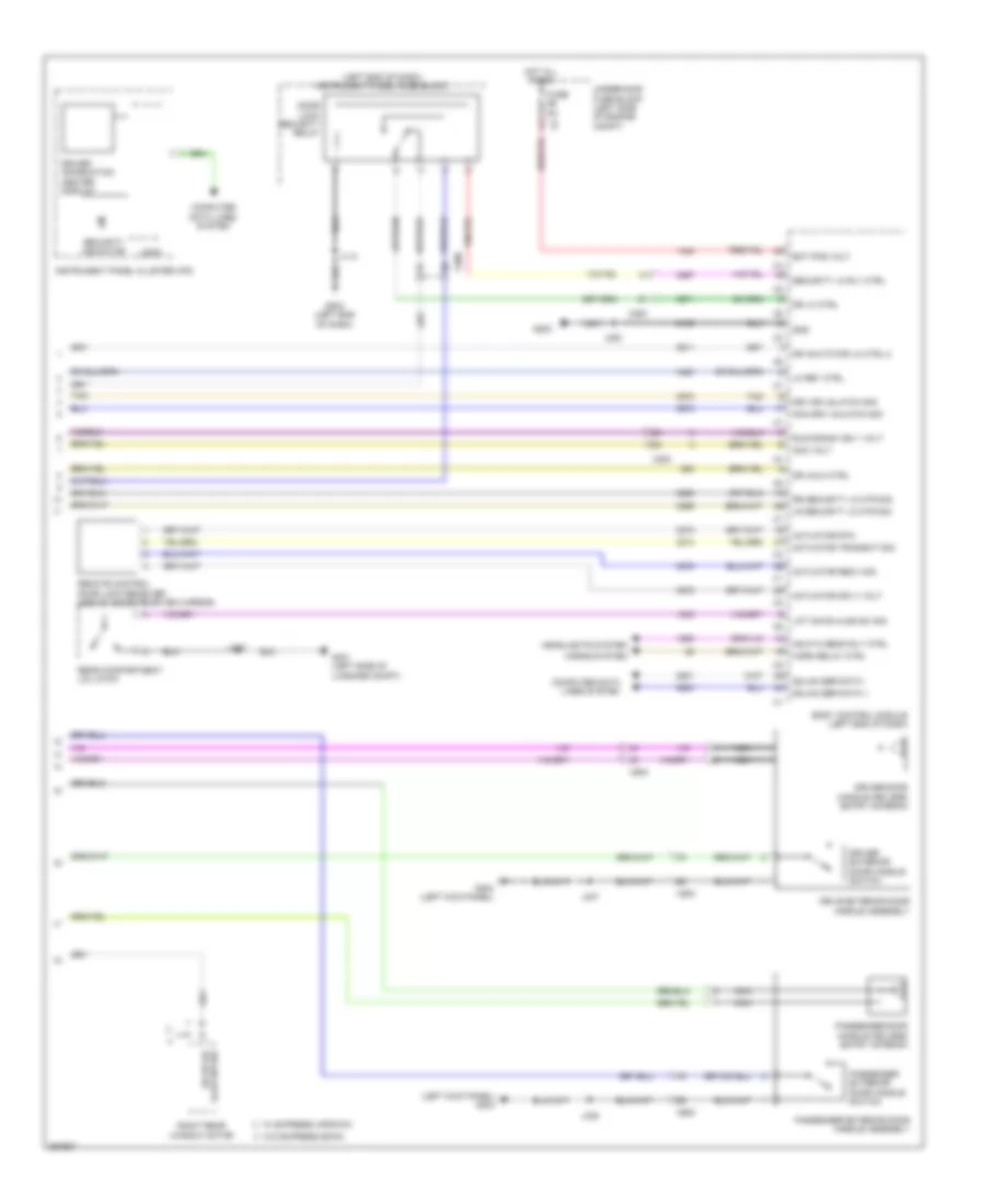
Forced Entry Wiring Diagram, with Passive Keyless Entry (3 of 3) for Saab 9-5 Aero 2011
List of elements for Forced Entry Wiring Diagram, with Passive Keyless Entry (3 of 3) for Saab 9-5 Aero 2011:
- (left end of dash) instrument panel fuse block
- (left kick panel) g304
- Acc volt
- Actuator recv sig
- Actuator rtn
- Actuator sply volt
- Actuator transmit sig
- Ajar sw sig rh rr dr
- Bat pos volt
- Body control module (left end of dash)
- Computer data lines system
- Door lock security relay
- Dr acutator lk ctrl 2
- Dr lk ctrl
- Dr unlk ctrl
- Drive exterior door handle assembly
- Driver door handle keyless entry antenna
- Driver exterior door handle switch
- Driver information center display
- Drv dr unlatch sig
- Fuse 5a
- G203
- G203 (left end of dash)
- G304 (left kick panel)
- G401 (left side of luggage compt)
- Gmlan ser data +
- Gmlan ser data -
- Gnd
- Hdlp hi beam rly ctrl
- Headlights system
- Horn relay ctrl
- Horns system
- Hot all times
- Instrument panel cluster (ipc)
- J113
- J220
- J335
- J337
- J410
- Lift gate ajar sw sig
- Lk rey ctrl
- Logic
- Lr security lk mtr sig
- Nca
- Non drv unlatch sig
- Passenger door handle keyless entry antenna
- Passenger exterior door handle assembly
- Passenger exterior door handle switch
- Rear compartment lid latch
- Remote control door lock receiver (above inside rearview mirror)
- Right rear window motor
- Rr security lk mtr sig
- Run/crank ign 1 volt
- Security indicator
- Security lk rly ctrl
- Tan
- Underhood fuse block (left side of engine compt)
- W/ express up/down
- W/o express down
- X200
- X500
- X600
Forced Entry Wiring Diagram, without Passive Keyless Entry for Saab 9-5 Aero 2011
List of elements for Forced Entry Wiring Diagram, without Passive Keyless Entry for Saab 9-5 Aero 2011:
- (in main bundle between breakout to side impact sensor lf & formed conduit near lf seat)
- (in main bundle between lower grommet & breakout to speaker) j803
- (left end of dash) g203
- (left end of dash) instrument panel fuse block
- (left side of engine compt) (w/ theft deterent body security content) underhood fuse block
- Actr rtn
- Actr unlck ctrl
- Batt pos volt
- Body control module (left end of dash)
- Center display
- Child lkout ind
- Child lockout security ind
- Computer data lines system
- Door lock security relay
- Dr lck ctrl (2)
- Dr lk ctrl
- Driver
- Driver door latch assembly
- Driver window motor (in driver's door)
- Drv dr lk sw lk sig
- Drv dr lk sw unlk sig
- Fuse 5a
- G109 (engine compt, on left strut tower)
- G201 (left kick panel)
- G203 (left end of dash)
- G302 (right kick panel)
- G401 (left side of luggage compt)
- Gmlan ser data (+)
- Gmlan ser data (-)
- Hdlp hi beam rly ctrl
- Headlights system horns system
- Horn rly ctrl
- Hot at all times
- Information
- Instrument panel cluster (ipc)
- Instrument panel multifunction switch
- Interior lights system
- J113
- J233 (in main bundle between breakout to lf door inline & g201)
- J311 (in main bundle between g201 & formed conduit near lf seat)
- J312 (in main bundle between g201 & formed conduit near lf seat)
- J314 (in main bundle between breakout to side impact sensor - lf & formed conduit near lf seat)
- J315
- J410
- J509
- J609
- J701
- J801
- Left rear door latch assembly
- Lf dr ajar sw sig
- Lk rly ctrl
- Logic
- Lr lk mtr status sig
- Passenger door latch assembly
- Passenger window motor (in passenger's door)
- Rcv sig
- Rear compartment lid latch
- Remo actr sply volt
- Remo actr trans sig
- Remo func actr rtn
- Remote control door lock receiver (above inside rearview mirror)
- Rf dr ajar sw sig
- Right rear door latch assembly
- Rr lk mtr status sig
- Security content
- Security indicator
- Security lk rly ctrl
- Security lk sw sig
- Sply volt
- Trans sig
- Trunk, tailgate, fuel doors system
- Underhood fuse block (left side of engine compt)
- W/ theft deterent body
- W/o theft deterent body
- X200
- X500
- X600
- X700
- X800
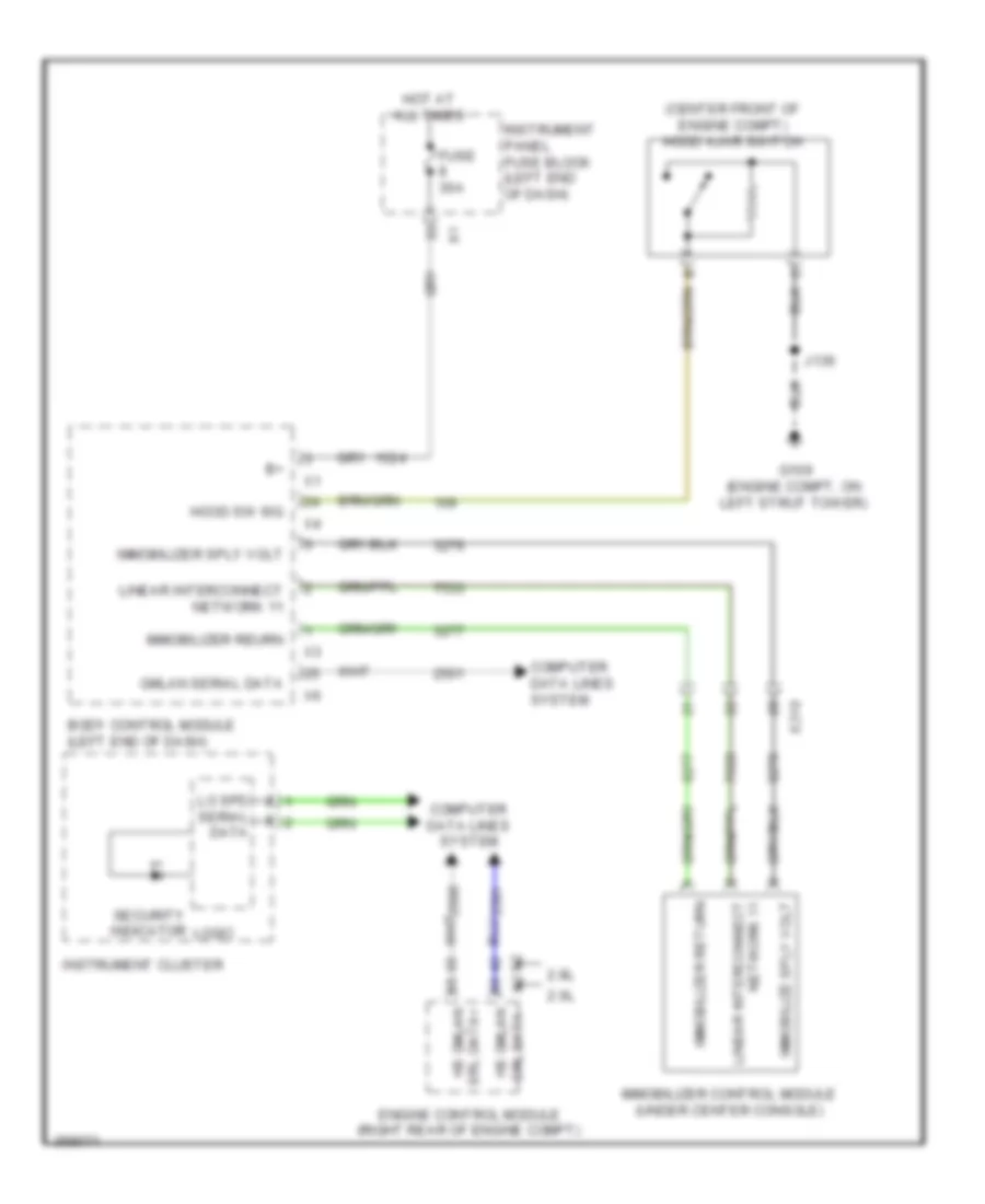
Immobilizer Wiring Diagram for Saab 9-5 Aero 2011
List of elements for Immobilizer Wiring Diagram for Saab 9-5 Aero 2011:
- (center front of engine compt) hood ajar switch
- 2.0l
- 2.8l
- Body control module (left end of dash)
- Computer data lines system
- Engine control module (right rear of engine compt)
- Fuse 30a
- G109 (engine compt, on left strut tower)
- Gmlan serial data
- Hood sw sig
- Hot at all times
- Hs gmlan
- Immobilize sply volt
- Immobilizer control module (under center console)
- Immobilizer return
- Immobilizer reurn
- Immobilizer sply volt
- Instrument cluster
- Instrument panel fuse block (left end of dash)
- J136
- Linear interconnect
- Linear interconnect network 11
- Lo spd serial data
- Logic
- Network 11
- Security indicator
- Srl data+
- X2 srl data- hs gmlan
- X210
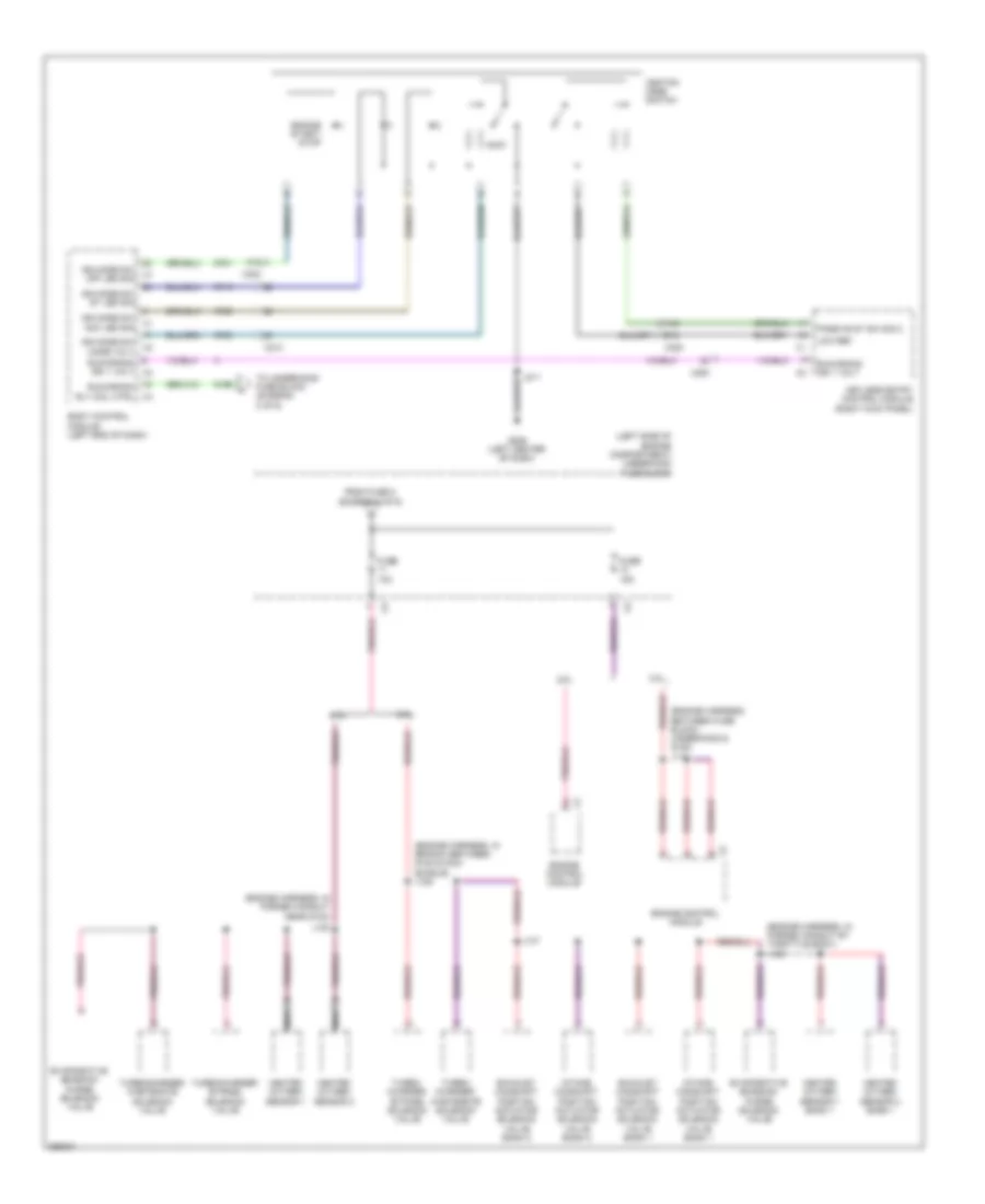
BODY CONTROL MODULES
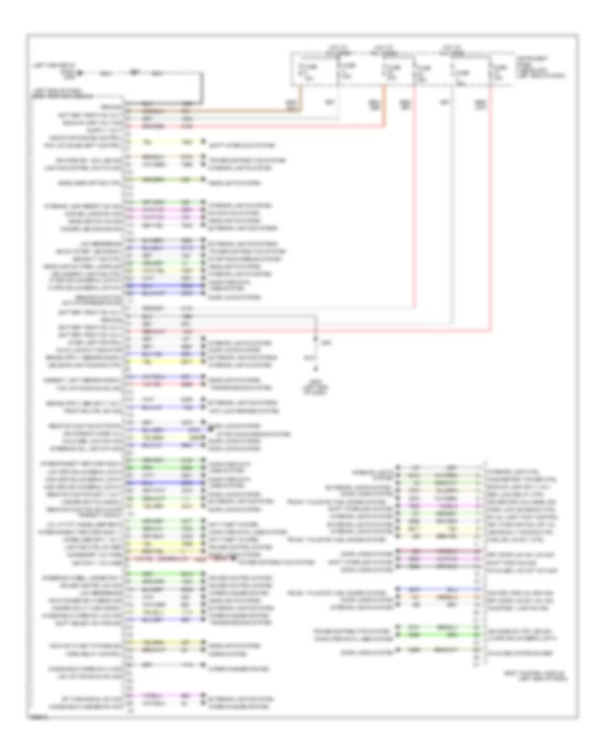
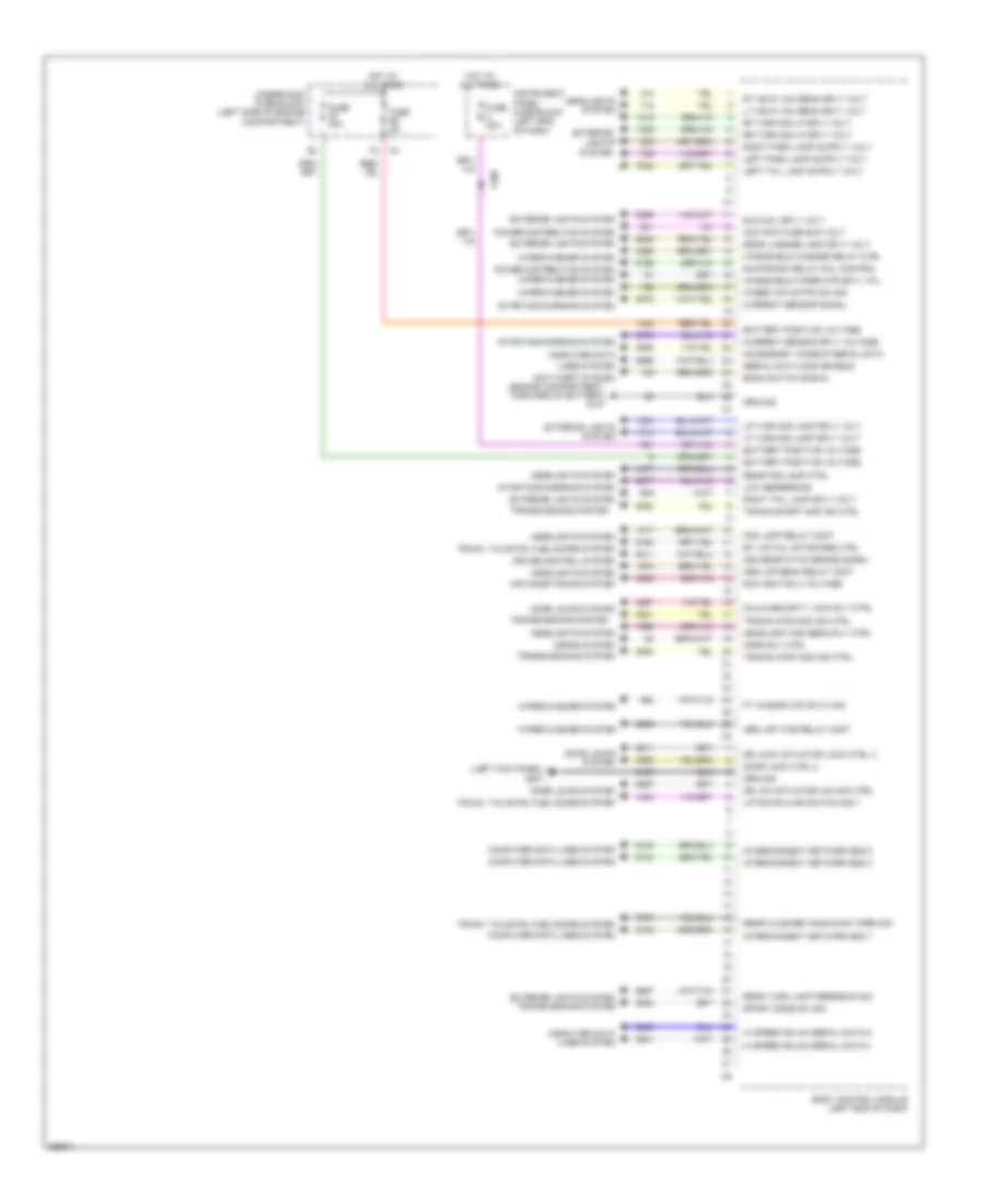
Body Control Modules Wiring Diagram (1 of 2) for Saab 9-5 Aero 2011
List of elements for Body Control Modules Wiring Diagram (1 of 2) for Saab 9-5 Aero 2011:
- (left center of dash) g206
- (left end of dash)
- (left end of dash) body control module
- (or 3)
- Accessory voltage
- Ambient light sensor signal
- Anti-lock brakes system
- Anti-theft system
- Backup lamp sply volt
- Backup lamp volt sig
- Battery positive volt
- Body control module
- Btlid/ lamp taigt control
- Child lockout indcator
- Child sec loc mot sta sig
- Child sec lock sw sig
- Child sec motor sig rer
- Computer data lines system
- Courtesy lamp sw sig
- Cruise control sw sig
- Cruise control system
- Door locks system
- Driver dor unlh enbl sig
- Drv door loc sw loc sig
- Drv door loc sw unl sig
- Drv otsd mir pud lmp vol
- Exterior lights system
- Exterior lights systems
- Fuel dr loc rly ctrl
- Fuse 15a
- Fuse 20a
- Fuse 25a
- Fuse 30a
- G203 (left end of dash)
- Ground
- Hazard led dimming sig
- Hazard sw lf turn signal
- Hazard switch signal
- Hdlp dimmer sw hi beam sig
- Hdlp sw flash to pass sig
- Headlamp sw on sig
- Headlamp sw park lamps sig
- Headlamps off sig ctrl
- Headlights system
- Hi spd gmlan serial data(+)
- High spd gmlan serial data+
- High spd gmlan serial data-
- Horn relay control
- Horns system
- Hot at all times
- Ign mode sw acc led sig
- Ign mode sw mode vol
- Ign mode sw off led sig
- Ign sw start led signal
- Ignition 1 voltage
- Immobilizer sply volt
- Inadvertent power ctrl
- Indicator dimming control
- Instrument panel fuse block (left end of dash)
- Inter lamp control
- Interconnect network bus 11
- Interconnect network bus 4
- Interior lamp ctrl
- Interior lamp defeat sw sig
- Interior lights system
- J216
- J220
- Lap up/tap down sw sig
- Led ambient lighting ctrl hi spd gmlan serial data(-)
- Led backlight dimming ctrl
- Led backlt dimming ctrl
- Lighting control switch sig
- Lighting ctrl sw ref
- Lo spd gmlan serial data
- Low reference
- Low spd gmlan serial data
- Navigation system
- Non drv dor unl ena sig
- Pak loc soled soft control
- Park lock solenoid ctrl
- Power distribution system
- Remote function actr rtn
- Remote function actuator receive sig
- Remote function actuator transmit signal
- Remote function sply volt
- Rf turn signal sw sig
- Sec lock relay ctrl
- Security ind ctrl
- Shift interlock system
- Shift position sig
- Shift select sw por sig
- Starting/charging system
- Steering col lock sta sig
- Steering wheel ladder sig 1
- Surveillance sw sig
- Top up/top down sw sig
- Traction ctrl sw sig
- Transmissions system
- Trunk, tailgate, fuel doors system
- Vcl at-tft immobilizer retn
- Windshield washer sw sig
- Windshield wiper sw hi sig
- Windshield wiper sw low sig
- Wiper/washer system
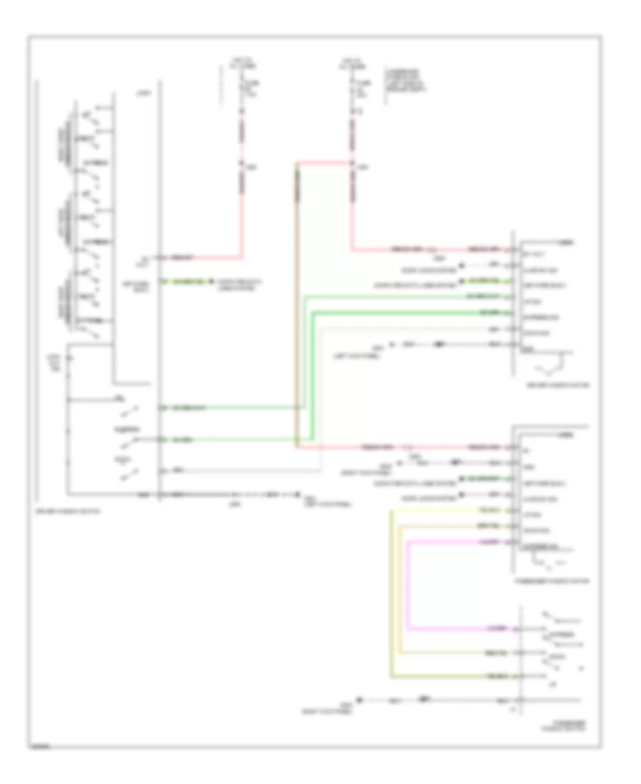
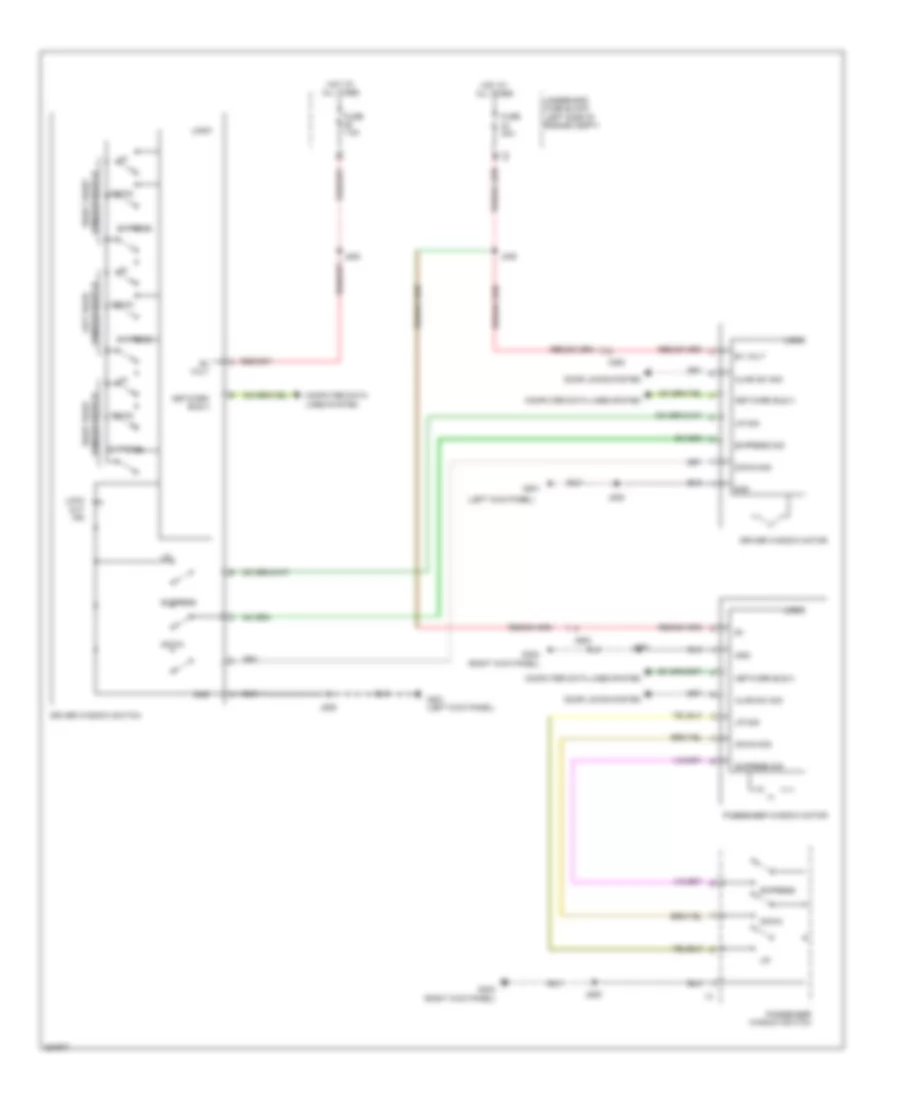
Body Control Modules Wiring Diagram (2 of 2) for Saab 9-5 Aero 2011
List of elements for Body Control Modules Wiring Diagram (2 of 2) for Saab 9-5 Aero 2011:
- (engine compartment, forward of battery) g107
- (left kick panel) g201
- Acc pow fuse sup volt
- Accessory wakeup serial data
- Air conditioning system
- Anti-theft system
- Battery positive voltage
- Body control module (left end of dash)
- Bonn switch signal
- Bt lid/tail motor res ctrl
- Child security lock rly ctrl
- Computer data
- Computer data lines system
- Cruise control system
- Cruise/etc/tcc brake signal
- Current sensor signal
- Current sensor sply voltage
- Door lock ctrl 2
- Door locks system
- Dr lck actuator unlock ctrl
- Dr lock actuator lock ctrl 2
- Exterior
- Exterior lights system
- Exterior lights system transmissions system
- Fog lamp relay cont
- Ft winscr wip sw hi sig
- Fuse 20a
- Fuse 5a
- Ground
- Headlamp high beam rly ctrl
- Headlights system
- Hed lmp beam relay cont
- Hed lmp was relay cont
- Hi speed gmlan serial data(+)
- Hi speed gmlan serial data(-)
- Horn rly ctrl
- Horns system
- Hot at all times
- Instrument panel fuse block (left end of dash)
- Interconnect network bus 1
- Interconnect network bus 2
- Interconnect network bus 3
- Lf turn sig lamp sply volt
- Liftgate ajar switch sig 1
- Lights system
- Lines system
- Low reference
- Lr turn sig lamp sply volt
- Lt hdlp low beam sply volt
- Power distribution system
- Rear closure handle sw open sig
- Rear fog lamp ctrl
- Rear license lamp sply volt
- Rear turn lamp feedback sig
- Rf turn sig lp sply volt
- Right tail lamp sply volt
- Rr turn sig lp sply volt
- Rt hdlp low beam sply volt
- Run ignition 3 voltage
- Run/crank relay coil control
- Serial data comm enable
- Slr coil sply volt
- Sport mode sw sig
- Starting/charging system
- Tramis comf mod ind ctrl
- Tramis inte mod ind ctrl
- Tramis sport mod ind ctrl
- Transmissions system
- Trunk, tailgate, fuel doors system
- Underhood fuse block (left side of engine compartment)
- Windshield washer relay ctrl
- Windshield wiper mtr sply vol
- Wiper/washer system
- Wiser wip motpk sw sig
- X200
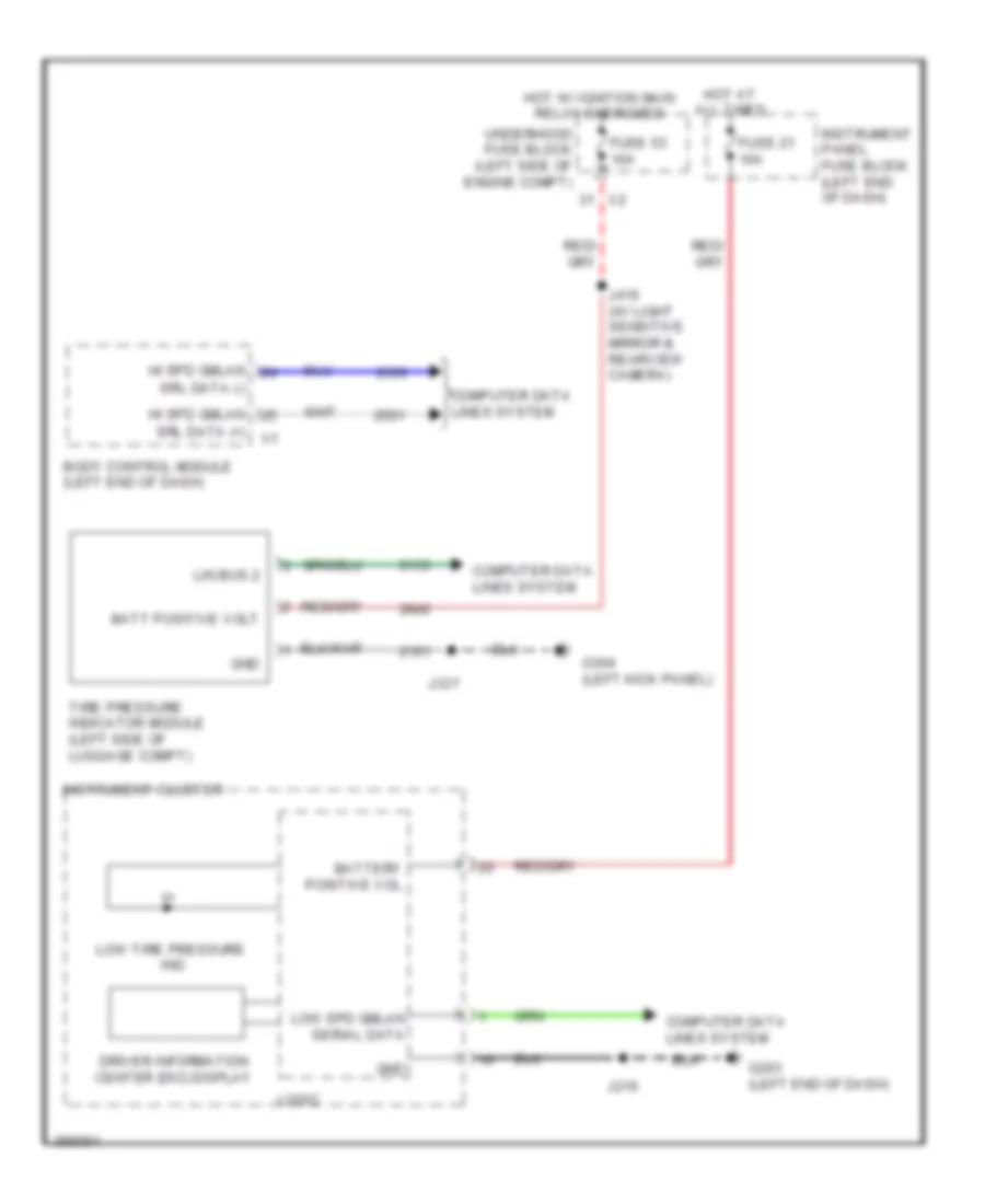
COMPUTER DATA LINES
Computer Data Lines Wiring Diagram (1 of 4) for Saab 9-5 Aero 2011
List of elements for Computer Data Lines Wiring Diagram (1 of 4) for Saab 9-5 Aero 2011:
- (body harness, in branch to body control module, near breakout to left front door inline) j232
- (body harness, in main bundle between breakout to left front door inline & g201) j236
- (body harness, in main bundle between breakout to left front door inline & g201) j243
- (instrument panel harness, in main bundle between g201 & data link connector) j225
- (instrument panel harness, in main bundle between g201 & data link connector) j226
- (instrument panel harness, in main bundle near data link resistor) j202
- (instrument panel harness, in main bundle near data link resistor) j203
- (left end of dash) g203
- A/t
- Acc wake-up data
- Body control module (left end of dash)
- Data link connector (dlc) (under left side of dash)
- Data link resistor (center of dash)
- Driver seat memory control module (under driver's seat)
- Driver window motor (in driver's door)
- Driver window switch
- Express down
- Express up/down
- Fuse 14 7.5a
- G206 (left center of dash)
- Gm lan ser data +
- Gm lan ser data -
- Hi spd gmlan
- Hi spd gmlan serial data bus + x2
- Hi spd gmlan serial data bus -
- Hot at all times
- Instrument panel fuse block (left end of dash)
- Left rear window motor (in left rear doors)
- Left rear window switch
- Lin interconnect network 2
- Linear intconn bus 3
- Linear intconn network 9
- Linear interconnect network 1
- Linear interconnect network 2
- Linear interconnect network 3
- Linear interconnect network 3 x6
- Linear interconnect network 4
- Low gmlan serial data
- Multi-axis acceleration sensor
- Passenger window motor (in passenger's door)
- Right rear window motor (in right rear doors)
- Right rear window switch
- Security siren (if equipped) (right rear of engine compt)
- Serial dat comm enable
- Serial data (+)
- Serial data (-)
- Serial data bus +
- Serial data bus -
- Steering wheel angle sensor (on steering column)
- Tire pressure indicator module (if equipped) (left side of luggage compt)
- Transmission shift lever
- X108
- X200
- X301
- X500
- X600
- X700
- X800
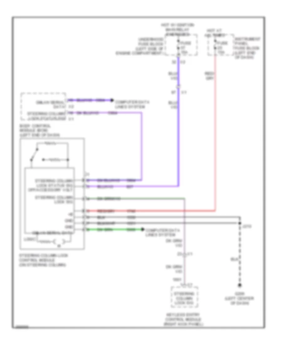
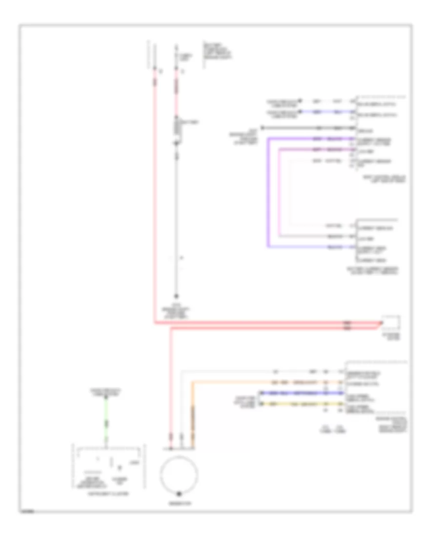
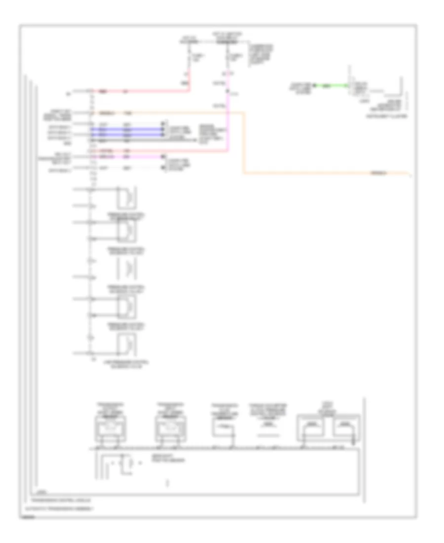
Computer Data Lines Wiring Diagram (2 of 4) for Saab 9-5 Aero 2011
List of elements for Computer Data Lines Wiring Diagram (2 of 4) for Saab 9-5 Aero 2011:
- (a/t) j117
- (engine harness, between fuse block- underhood & g120)
- (if equipped)
- (instrument panel harness, in main bundle in formed conduit, near center of instrument panel) j218
- (instrument panel harness, in main bundle near instrument cluster)
- 2.0l
- 2.8l
- A/t
- Accessory/ crank ign 0 volt
- Control solenoid valve assembly (a/t) (inside transmission)
- Digital radio receiver control module (if equipped)
- Engine control module (right rear of engine compt)
- Gm lan ser data +
- Gm lan ser data -
- Gm lan serial data
- Head up display
- Headlamp control module (left end of dash)
- High speed gmlan serial data bus +
- Hvac control module (center of dash)
- In temp sens sig
- Inflatable restraint sensing & diagnostic module (front of center console)
- Info display module
- Instrument cluster
- J217
- Linear intc
- Lo spd gmlan serial data
- Low speed gm lan data
- Low speed gmlan data
- M/t
- Mid serial data (+)
- Mid serial data (-)
- Mid spd gmlan serial data +
- Mid spd gmlan serial data -
- Mobile telephone control module (center of dash)
- Multimedia player interface module (if equipped) (right end of dash)
- Multimedia player interface module (kta+uye/uyj) (right end of dash)
- Radio
- Radio/hvac control module
- Rear audio control module (if equipped)
- Ser data comm enable
- Serial data
- Serial data bus +
- Serial data bus -
- Steering column lock control module (on steering column)
- Temp sens sig
- Tr7
- W/ digital audio system broadcast
- W/o digital audio system broadcast
- X210
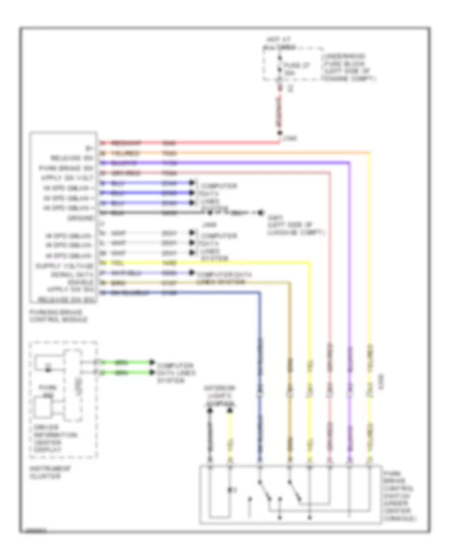
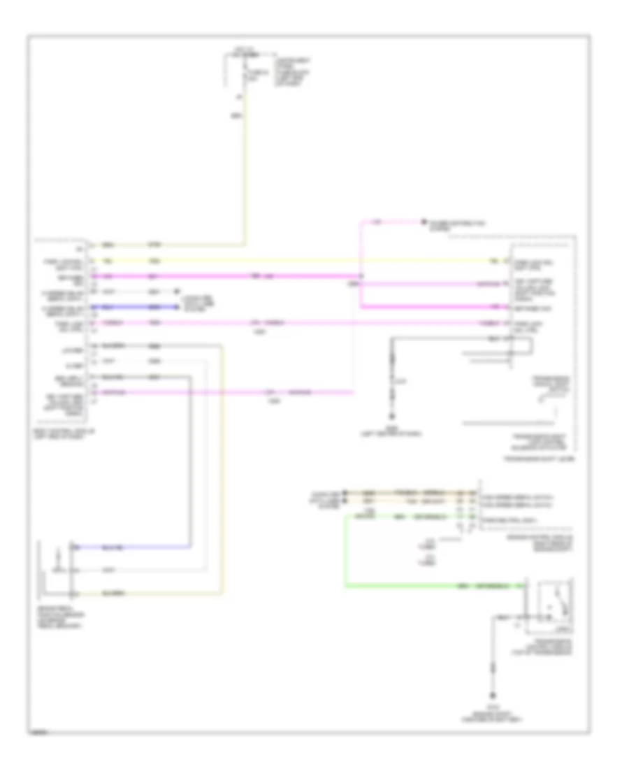
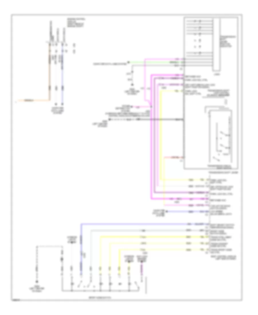
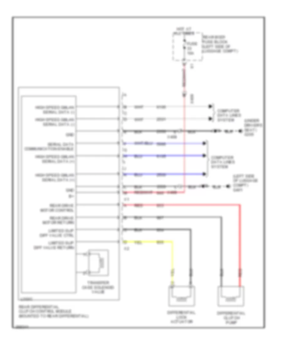
Computer Data Lines Wiring Diagram (3 of 4) for Saab 9-5 Aero 2011
List of elements for Computer Data Lines Wiring Diagram (3 of 4) for Saab 9-5 Aero 2011:
- (body harness, in branch to left rear wheel well, between breakout to keyless entry antenna & main bundle)
- (body harness, in main bundle between breakout to electronic brake control module & left bulkhead grommet)
- (body harness, in main bundle between breakout to left front door inline & g201)
- (body harness, in main bundle between breakout to left front door line & g201) j231
- (body harness, in main bundle between g401 & breakout to left rear wheel well)
- (lower left rear engine compt) electronic brake control module
- (right side of luggage compt) (lau/lhu/llu) fuel pump control module
- -f45/ f46 lau/ ldk
- 2.0l
- 2.8l
- B11
- Between g401 & breakout to left rear wheel well)
- Control module
- D9 serial data -
- Data comm enable
- F46+ f45/ ldk +lau/
- Gm lan ser data
- Hi spd gmlan serial data (+)
- Hi spd gmlan serial data (-)
- J141
- J142
- J237
- J238
- J405
- J406
- J407 (body harness, in branch to left rear wheel well, between breakout to keyless entry antenna & grommet)
- J408
- J414
- K3 serial data +
- Lau/ ldk
- Lau/ldk -f45/f46 +lau/ldk
- Linear intc
- P data comm enable
- Parking brake
- Power steering control module (if equipped) (lower left side of dash)
- Rear differential clutch control module (if equipped) (mounted to rear differential)
- Ser data (+)
- Ser data (-)
- Serial data +
- Serial data -
- Serial data bus (+)
- Serial data bus (-)
- Suspension control module (if equipped) (left side of luggage compt)
- Telematics communication interface control module (if equipped) (center of dash)
- Transmission control module (top of transmission)
- W/ awd
- W/ chassis continuously variable real time damping & w/o awd
- X200
- X408
Computer Data Lines Wiring Diagram (4 of 4) for Saab 9-5 Aero 2011
List of elements for Computer Data Lines Wiring Diagram (4 of 4) for Saab 9-5 Aero 2011:
- C3u+utv/ce1
- Ce1
- Ce1-c3u+utv
- Driver seat heating control module (w/ front seat heater) (under driver's seat)
- Inside rearview mirror (control intelligent high beam)
- J313 (body harness, in main bundle between g305 & formed conduit near left front seat)
- J339 (body harness, in main bundle rearward of formed conduit near left b-pillar, near c-pillar)
- Keyless entry control module (right kick panel)
- Left side object sensor (if equipped) (behind left side of front bumper)
- Linear interconnect network 1
- Linear interconnect network 9
- Lo spd gmlan serial data
- Outside rearview mirror switch
- Parking assist control module (if equipped) (left side of luggage compt)
- Passenger presence detection module (if equipped) (under front passenger's seat)
- Passenger window switch
- Rain sensor (w/ windshield wiper system)
- Right side object sensor (behind right side of front bumper)
- Sunroof motor (forward of sunroof)
- Sunroof sunshade motor module (if equipped) (top center rear of roof)
- Ultrasonic intrusion sensor (in overhead console)
- Utv
- Vehicle direction camera control module (if equipped) (above headliner)
- X301
- X307
- X397
- X500
- X600
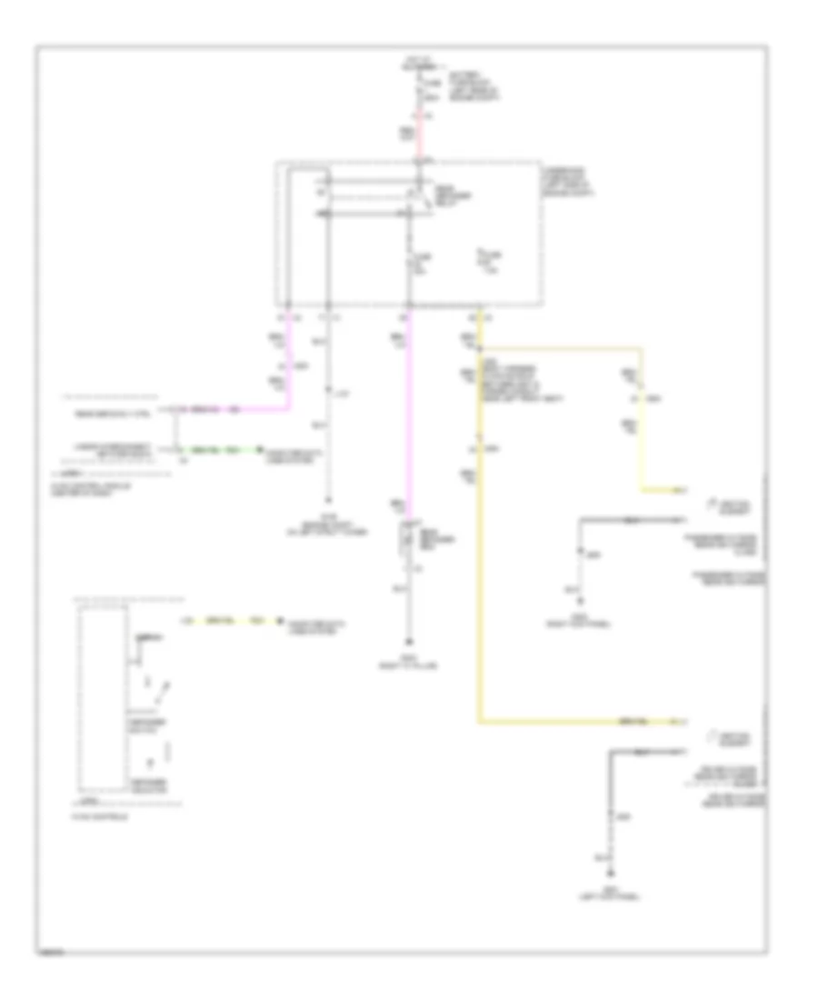
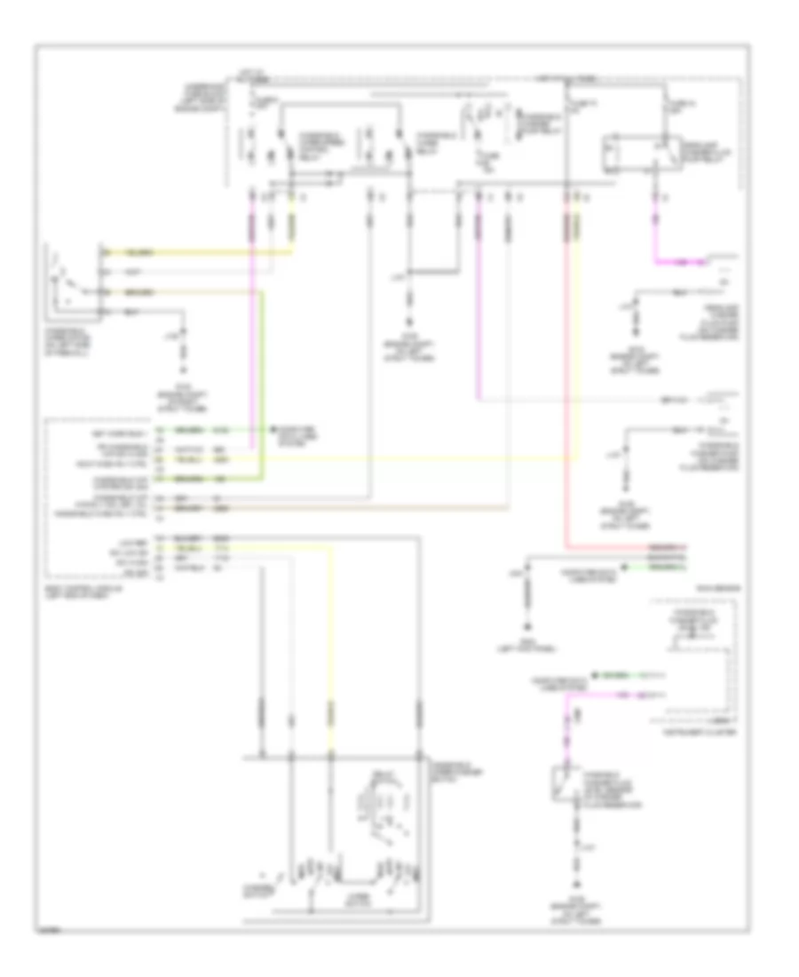
COOLING FAN
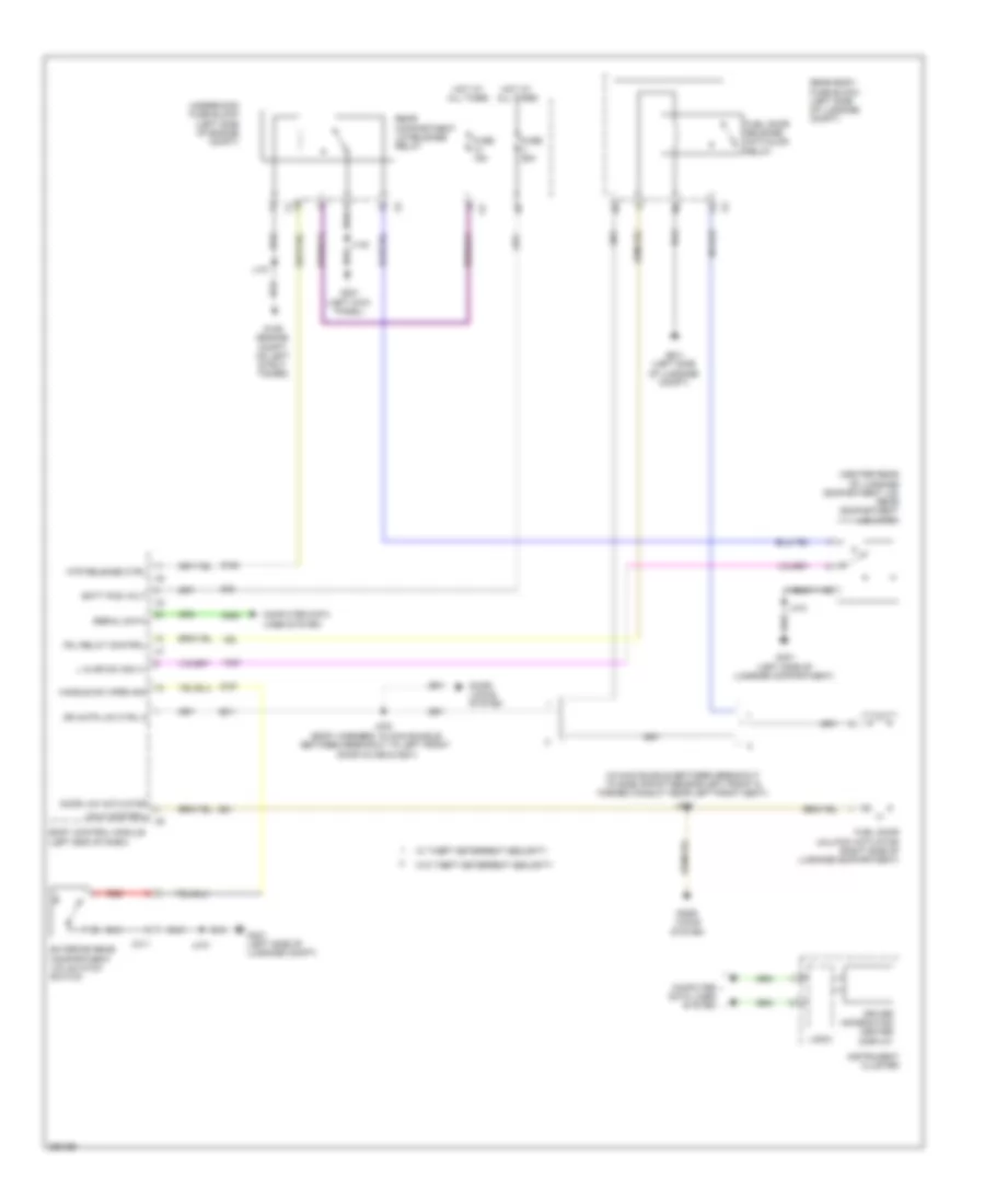
Cooling Fan Wiring Diagram, Dual Fans (1 of 2) for Saab 9-5 Aero 2011
List of elements for Cooling Fan Wiring Diagram, Dual Fans (1 of 2) for Saab 9-5 Aero 2011:
- (not used)
- (or 151)
- (or 2761)
- (or tan)
- 2.0l
- 2.8l
- Computer data lines system
- Cooling fan high speed relay
- Cooling fan low speed relay
- Cooling fan relay
- Cooling fan speed control relay
- Engine control module (right rear of engine compt)
- Engine controls system
- Engine coolant temperature sensor (right rear of engine)
- Fuse 10a
- Fuse 30a
- Fuse 42 20a
- G109 (engine compt, on left strut tower)
- Hi spd cooling fan rly
- Hot at all times
- Hot w/ engine control module relay energized
- J115 (engine harness, between fuse block- underhood & g120)
- J126 (2.8l) (engine harness, in formed conduit by throttle body)
- J137
- Left cooling fan motor (behind radiator)
- Lw spd cooling fan rly
- Underhood fuse block (left side of engine compt)
- X117
- X119
- X3 (not used)
Cooling Fan Wiring Diagram, Dual Fans (2 of 2) for Saab 9-5 Aero 2011
List of elements for Cooling Fan Wiring Diagram, Dual Fans (2 of 2) for Saab 9-5 Aero 2011:
- (engine compartment, left center of radiator support)
- (engine cooling harness, on branch, between main bundle & relay block - underhood)
- Cooling fan speed control 2 relay
- G106
- J105 (engine cooling harness, main bundle & on branch, between relay block- underhood)
- J106 (engine cooling harness, on branch, between main bundle & relay block-underhood)
- J107
- J108
- Left cooling fan medium speed relay
- Right cooling fan medium speed relay
- Right cooling fan motor (behind radiator)
- Underhood relay block (left side of engine compt)
- X117
Cooling Fan Wiring Diagram, Single Fan for Saab 9-5 Aero 2011
List of elements for Cooling Fan Wiring Diagram, Single Fan for Saab 9-5 Aero 2011:
- (engine harness, between fuse block-underhood & g120)
- (not used)
- (or 151)
- (or 2761)
- (or tan)
- 2.0l
- 2.8l
- Computer data lines system
- Cooling fan high speed relay
- Cooling fan medium speed 1 relay
- Cooling fan medium speed 2 relay
- Cooling fan motor (behind radiator)
- Cooling fan relay
- Cooling fan speed control relay
- Engine control module (right rear of engine compt)
- Engine control module relay
- Engine controls system
- Engine coolant temperature sensor (right rear of engine)
- Engine main rly coil ctrl
- Fan rly ctrl lw spd cooling
- Fuse 10a
- Fuse 60a
- G106 (engine compartment, left center of radiator support)
- G109 (engine compartment, on left strut tower)
- Hi spd cooling fan rly ctrl
- Hot at all times
- J115
- J126 (2.8l) (engine harness, in formed conduit by throttle body)
- J137
- Underhood fuse block (left side of engine compt)
- X117
CRUISE CONTROL
Cruise Control Wiring Diagram for Saab 9-5 Aero 2011
List of elements for Cruise Control Wiring Diagram for Saab 9-5 Aero 2011:
- (instrument panel harness, on branch leading to info display module)
- (or 151)
- (or 416)
- (or 560)
- (or 561)
- (or tan)
- 2.0l turbo
- 2.8l turbo
- 5 voct ref
- 5 volt ref
- 5v4
- Accelerator pedal position sensor (on pedal bracket)
- Automatic transmission assembly
- Body control module (left end of dash)
- Brake pedal position sensor (on brake pedal bracket)
- Brake sig
- Brk sply vol
- Cancel
- Cltc sply low ref
- Cltc sply sig
- Cltc sply vol ref
- Clutch pedal position sensor (2.0l turbo) (on clutch pedal bracket)
- Computer data lines system
- Cruise ctrl sw sig
- Cruise ind
- Cruise switch
- Driver information center display
- Engine control module (right rear of engine compt)
- Fuse 10a
- Fuse 15a
- Fuse 5a
- G121 (2.0l: left side of engine) (2.8l: right side of engine)
- G206 (left end of dash)
- Ground
- High signal
- Hot at all times
- Hot w/ ignition main relay energized
- Ign
- Instrument cluster
- Instrument panel fuse block (left end of dash)
- Interior lights system
- J113
- J114
- J205
- J216
- Left steering wheel controls switch
- Logic
- Low ref
- Low signal
- Nca
- Pdl position sig 1
- Pdl position sig 2
- Pnk
- Positive voltage
- Res+
- Sensor sig
- Ser data
- Ser data +
- Ser data -
- Serial bus +
- Serial bus -
- Serial data (+)
- Serial data (-)
- Set-
- Sound systems
- Steering wheel air bag coil
- Sw ref
- Tan
- Throttle body actuator (integral with throttle body)
- Tp mtr low ref
- Tp mtr sply volt
- Tp sens sig 1
- Tp sens sig 2
- Transmission control module
- Transmission input shaft speed sensor
- Transmission output shaft speed sensor
- Underhood fuse block (left side of engine compt)
- Vehicle speed sensor (2.0l turbo)
- Vss hi sig
- Vss lo sig
- Vss ref
- X108
- X200
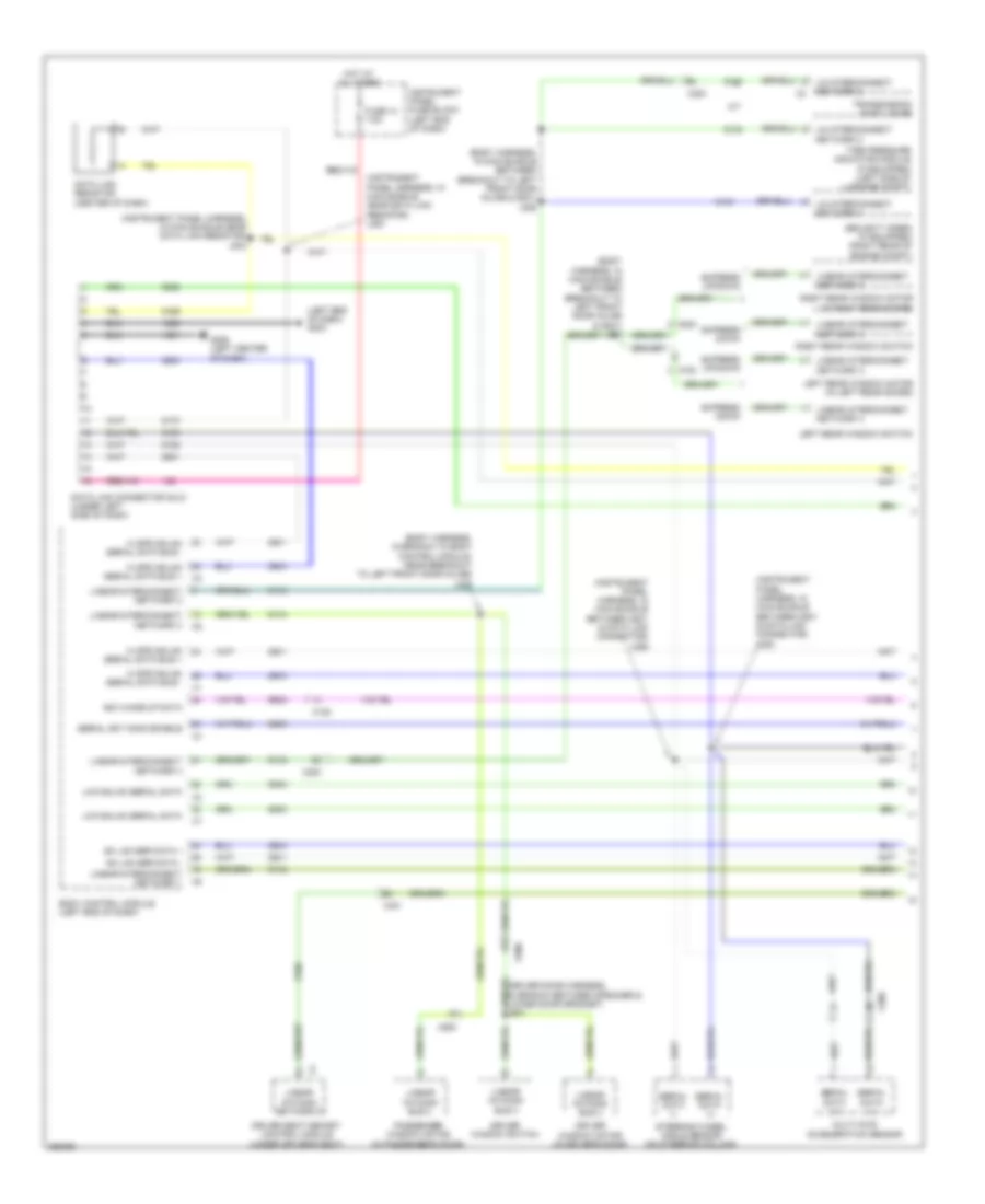
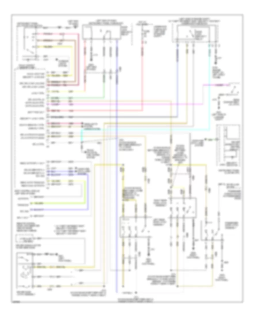
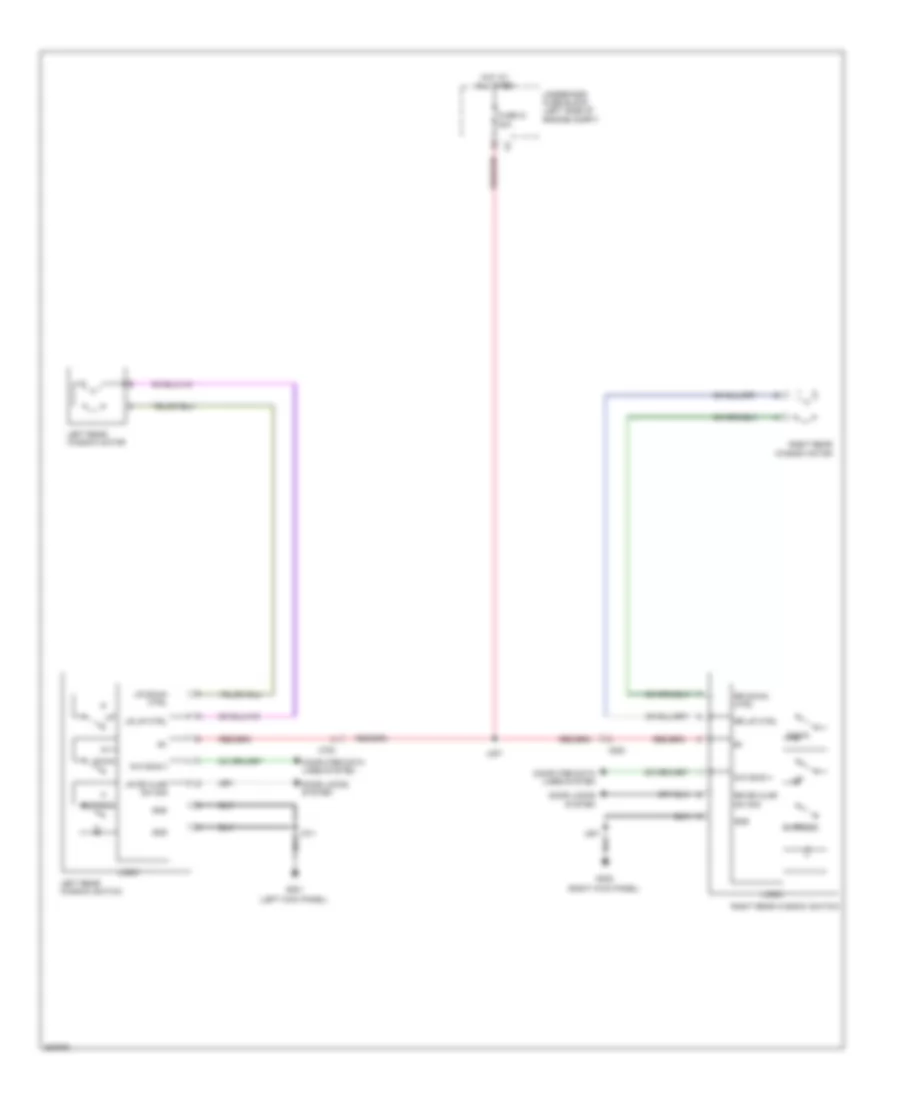
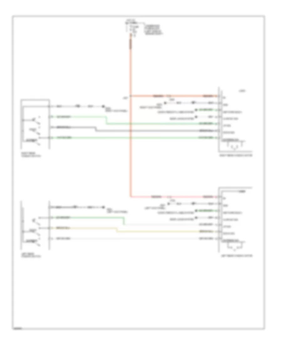
DEFOGGERS
Defoggers Wiring Diagram for Saab 9-5 Aero 2011
List of elements for Defoggers Wiring Diagram for Saab 9-5 Aero 2011:
- Battery fuse block (left rear of engine compt)
- Computer data lines system
- Defogger indicator
- Defogger switch
- Display
- Driver outside rearview mirror
- Driver outside rearview mirror class
- Fuse 250a
- Fuse 40a
- Fuse 7.5a
- G109 (engine compt, on left strut tower)
- G201 (left kick panel)
- G302 (right kick panel)
- G404 (right "c" pillar)
- Heating element
- Hot at all times
- Hvac control module (center of dash)
- Hvac controls
- J137
- J509
- J609
- Linear interconnect network bus 9
- Logic
- Passenger outside rearview mirror
- Passenger outside rearview mirror class
- Rear defog rly ctrl
- Rear defogger grid
- Rear defogger relay
- Underhood fuse block (left side of engine compt)
- X2 a
- X200
- X500
- X600
ELECTRONIC POWER STEERING
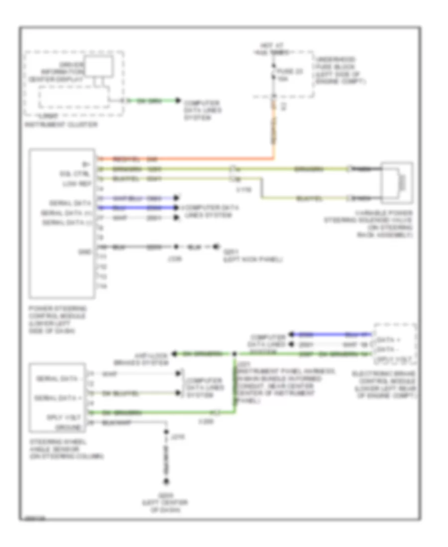
Electronic Power Steering Wiring Diagram for Saab 9-5 Aero 2011
List of elements for Electronic Power Steering Wiring Diagram for Saab 9-5 Aero 2011:
- Anti-lock brakes system
- Computer data lines
- Computer data lines system
- Data +
- Data -
- Driver information center display
- Electronic brake control module (lower left rear of engine compt)
- Fuse 23 10a
- G201 (left kick panel)
- G206 (left center of dash)
- Gnd
- Ground
- Hot at all times
- Instrument cluster
- J215
- J221 (instrument panel harness, in main bundle in formed conduit, near center center of instrument panel)
- J336
- Logic
- Low ref
- Nca
- Power steering control module (lower left side of dash)
- Serial data
- Serial data (+)
- Serial data (-)
- Serial data +
- Serial data -
- Sol ctrl
- Sply volt
- Steering wheel angle sensor (on steering column)
- System
- Underhood fuse block (left side of engine compt)
- Variable power steering solenoid valve (on steering rack assembly)
- X116
- X200
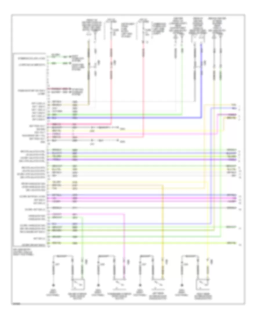
ELECTRONIC SUSPENSION
Electronic Suspension Wiring Diagram for Saab 9-5 Aero 2011
List of elements for Electronic Suspension Wiring Diagram for Saab 9-5 Aero 2011:
- (body harness, in main bundle between breakout to left front door inline & left bulkhead grommet)
- (body harness, in main bundle between breakout to left front door inline & left bulkhead grommet) j228
- (body harness, in main bundle rearward of formed conduit near left b-pillar, near c-pillar) j340
- All times
- Bat pos volt
- Computer data lines system
- Driver information center display
- Fuse 31 10a
- G304 (left kick panel)
- Gmlan ser data (+)
- Gmlan ser data (-)
- Gnd
- Hot at
- Ign
- Instrument cluster
- Instrument panel fuse block (left end of dash)
- J229
- J337
- Left front shock absorber actuator (left front strut)
- Left front vertical body acceleration sensor (left front rear corner of engine compt)
- Left front vertical suspension acceleration sensor (near top of left bottom of left strut)
- Left rear shock absorber actuator (left rear strut)
- Lf accel sig
- Lf damp serv ctrl
- Lf damp serv sply volt
- Lf whl acc low ref
- Lf whl acce vol ref
- Lf whl damp accel sig
- Logic
- Lr damp serv ctrl
- Lr damp serv sply volt
- Rear accel sig
- Rear vertical body acceleration sensor (behind left rear seat)
- Rf accel sig
- Rf damp serv ctrl
- Rf damp serv sply volt
- Rf whl damp accel sig
- Right front shock absorber actuator (right front strut)
- Right front vertical body acceleration sensor (right front rear corner of engine compt)
- Right front vertical suspension acceleration sensor (near top of right front steering knuckle)
- Right rear shock absorber actuator (right rear strut)
- Rr damp serv ctrl
- Rr damp serv sply volt
- Serial data comm enable
- Suspension control module (left side of luggage compt)
- X106
- X107
- X108
- X113
- X114
- X401
- X402
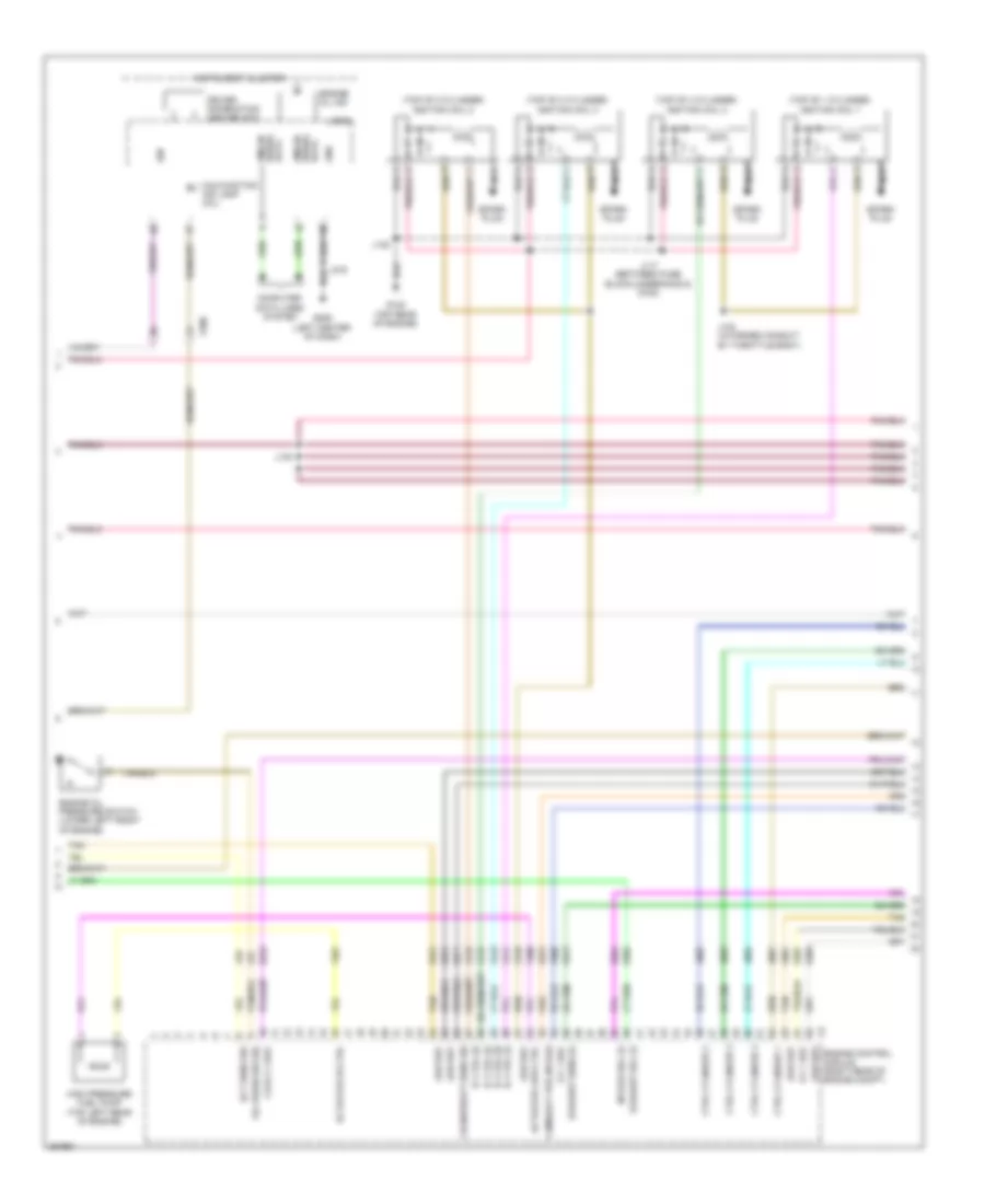
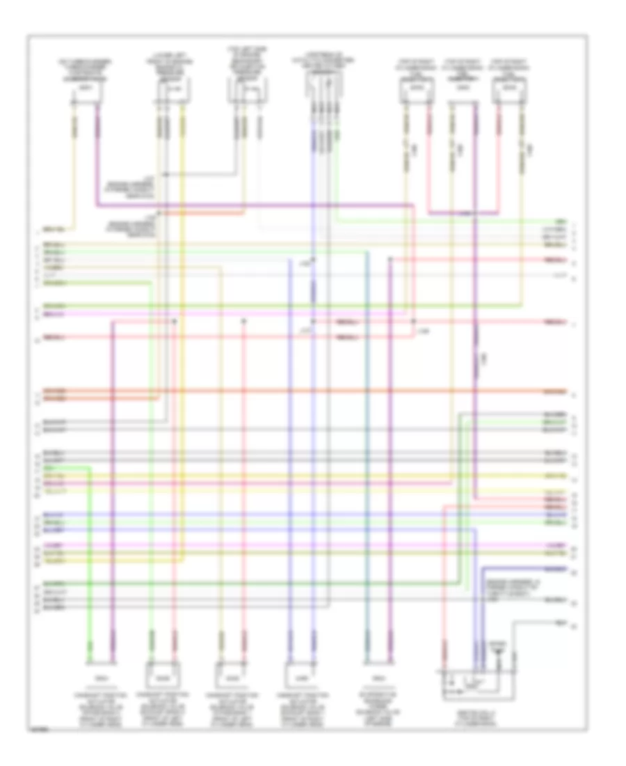
ENGINE PERFORMANCE
2.0L TURBO
2.0L Turbo, Engine Performance Wiring Diagram (1 of 5) for Saab 9-5 Aero 2011
List of elements for 2.0L Turbo, Engine Performance Wiring Diagram (1 of 5) for Saab 9-5 Aero 2011:
- (in main bundle forward of breakout to right rear wheel well) j401
- (on bottom right side of radiator) a/c refrigerant pressure sensor
- (on pedal bracket) accelerator pedal position (app) sensor
- 5-v ref
- A/c refrigerant pressure sens sig
- Accessory vol
- Air pressure sig
- App sens sig (1)
- App sens sig (2)
- Cltc sply low ref
- Cltc sply sig
- Cltc sply vol ref
- Clutch pedal position sensor (m/t) (on clutch pedal bracket)
- Computer data lines system
- Cooling fan rly ctrl
- Cooling fans system
- Cruise control system
- Cruise/etc/tcc brake sig
- Engine control module (right rear of engine compt)
- Engine ctrl ign rly
- Engine ind ctrl
- Evap conister vent sol ctrl
- Evaporative emission vent solenoid valve (top left side of engine)
- Fuel level sens sig
- Fuel pump & level sensor assembly
- Fuel pump primary rly ctrl
- Fuel tank pressure sens sig
- Fuel tank pressure sensor (on fuel pump & sender assembly)
- Fuel temp/composition sig
- Fuse 10a
- Fuse 15a
- Gmlan serial data bus + (1)
- Gmlan serial data bus - (1)
- Hot at all times
- Ign
- Intake manifold pressure & air temperature sensor (on engine intake air duct)
- Low ref
- Low speed cooling fan rly ctrl
- Pre-throttle air press temp sig
- Starter enable rly ctrl
- Starting/charging system
- Tan
- Tan a
- Underhood fuse block (left side of engine compt)
- X108
- X108 computer data lines system
- X115
- X118
- X200
- X350
- X403
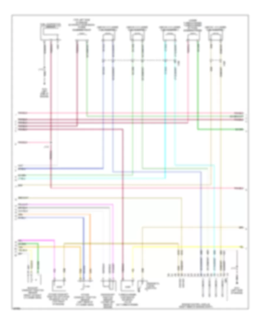
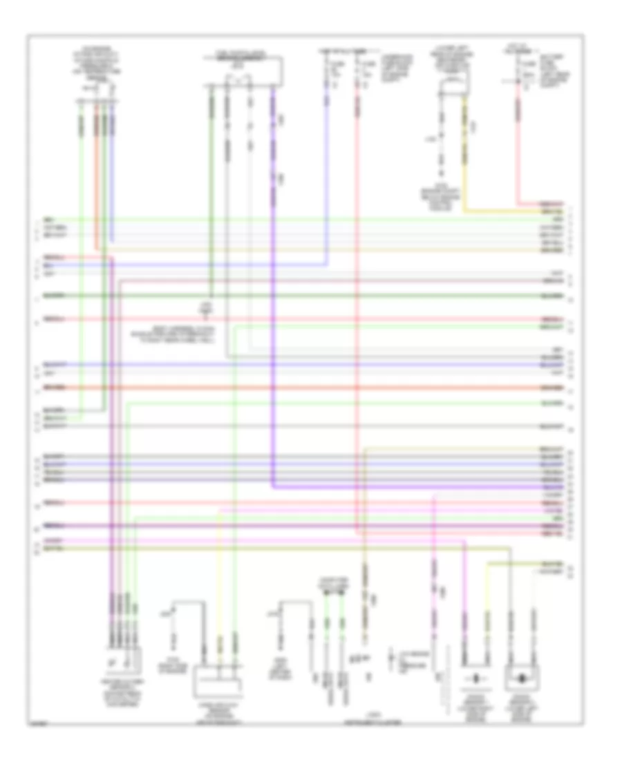
2.0L Turbo, Engine Performance Wiring Diagram (2 of 5) for Saab 9-5 Aero 2011
List of elements for 2.0L Turbo, Engine Performance Wiring Diagram (2 of 5) for Saab 9-5 Aero 2011:
- (on steering column) steering column lock control module
- (top of transmission) transmission control module
- 5-v ref
- 87a
- Batt vol
- Battery fuse block (left rear of engine compt)
- Body control module (left end of dash)
- Coil ctrl
- Computer data lines system
- Data bus +
- Data bus -
- Engine control module relay
- Engine coolant temperature sensor (right rear of engine)
- Exhaust camshaft position actuator solenoid valve (front of right cylinder bank)
- Fuel pressure sensor
- Fuel pump control module (right side of luggage compt)
- Fuel pump sply
- Fuse 10a
- Fuse 15a
- Fuse 20a
- Fuse 250a
- Fuse 5a
- Fuse 7.5a
- G109 (engine compt, on left strut tower)
- G306 (right rear of luggage compt)
- Gnd
- Hot at all times
- Ign
- Ign 1 volt
- Ignition main relay
- J114
- J137
- Logic
- Low ref
- Relay ctrl
- Sens sig
- Serial data
- Tan
- Underhood fuse block (left side of engine compt)
- X108
- X200
- X403
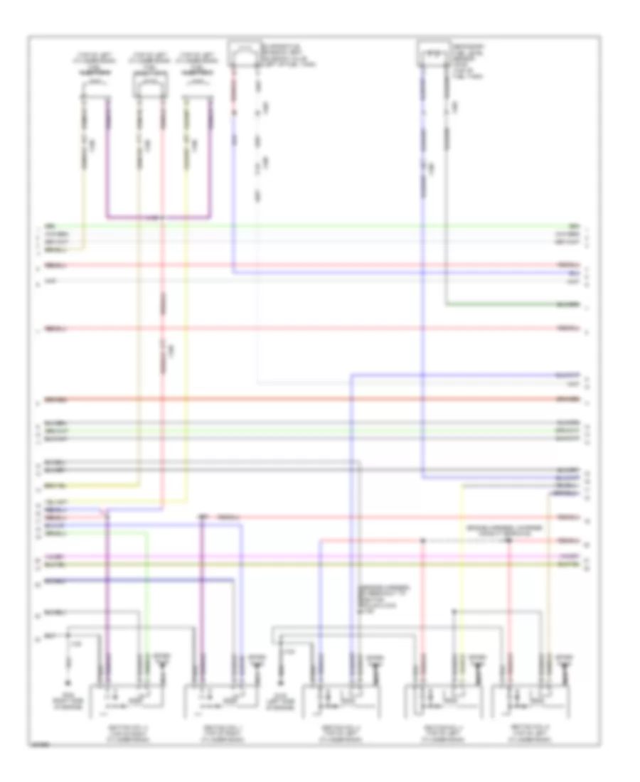
2.0L Turbo, Engine Performance Wiring Diagram (3 of 5) for Saab 9-5 Aero 2011
List of elements for 2.0L Turbo, Engine Performance Wiring Diagram (3 of 5) for Saab 9-5 Aero 2011:
- (top of 1 cylinder)
- (top of 2 cylinder)
- (top of 3 cylinder)
- (top of 4 cylinder)
- 5-v 1 ref
- 5-volt 2 ref
- Actuator hi ctrl
- Actuator low ctrl
- Camshaft pos intake
- Computer data lines system
- Crankshaft sens sig
- Ctrl cylinder 1
- Ctrl cylinder 2
- Ctrl cylinder 3
- Ctrl cylinder 4
- Data
- Driver information center (dic)
- Ect sens sig
- Engine control module (right rear of engine compt)
- Engine oil ind
- Engine oil pressure switch (lower left front of engine)
- Exhaust sens (1)
- Exhaust sol (1)
- G122 (top rear of engine)
- G206 (left center of dash)
- Gnd
- High pressure fuel pump (top left rear of engine)
- Ic ctrl (1)
- Ic ctrl (2)
- Ic ctrl (3)
- Ic ctrl (4)
- Ign
- Ignition coil 1
- Ignition coil 2
- Ignition coil 3
- Ignition coil 4
- Instrument cluster
- Intake sol (1)
- J117 (between fuse block-underhood & g120)
- J122
- J124 (in formed conduit by throttle body)
- J130
- J216
- Logic
- Low ref
- Malfunction ind lamp (mil)
- Nca
- Oil press sw sig
- Serial gmlan
- Spark plug
- Tan
- X200
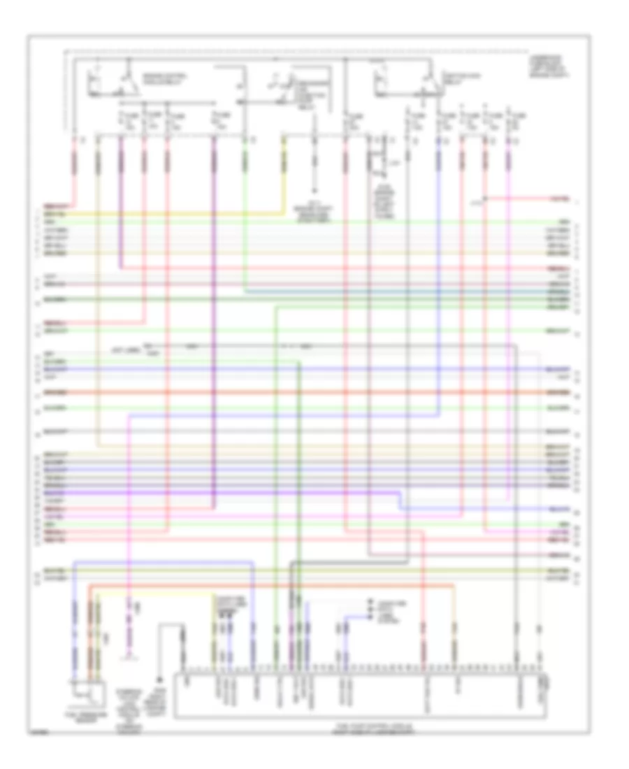
2.0L Turbo, Engine Performance Wiring Diagram (4 of 5) for Saab 9-5 Aero 2011
List of elements for 2.0L Turbo, Engine Performance Wiring Diagram (4 of 5) for Saab 9-5 Aero 2011:
- (above 1 cylinder)
- (above 2 cylinder) fuel injector 2
- (above 3 cylinder) fuel injector 3
- (above 4 cylinder) fuel injector 4
- (top left side of engine) evaporative emission purge solenoid valve
- (under turbocharger) turbocharger by-pass solenoid valve
- Crankshaft position sensor (lower left rear of engine)
- Engine control module (right rear of engine compt)
- Engine oil level switch
- Exhaust camshaft position sensor (front of right cylinder head)
- Fuel composition sensor
- Fuel injector 1
- G121 (left side of engine)
- Gnd
- Intake camshaft position actuator solenoid valve (top front of engine)
- Intake camshaft position sensor (left rear of cylinder head)
- J113
- J118
- Low ref
- Sply cylinder 1
- Sply cylinder 2
- Sply cylinder 3
- Sply cylinder 4
- Tan
- Turbocharger wastegate solenoid valve (on turbocharger)
- X160
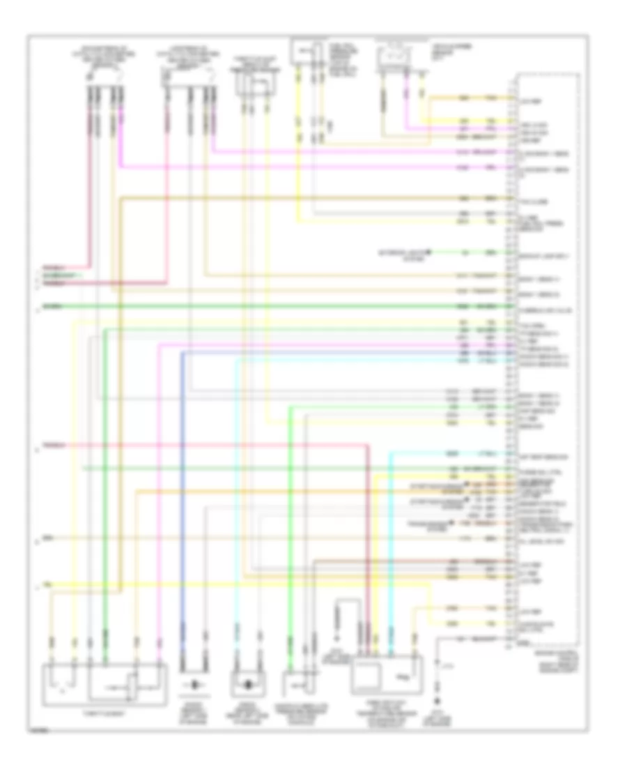
2.0L Turbo, Engine Performance Wiring Diagram (5 of 5) for Saab 9-5 Aero 2011
List of elements for 2.0L Turbo, Engine Performance Wiring Diagram (5 of 5) for Saab 9-5 Aero 2011:
- (downstream of catalytic converter) heated oxygen sensor 2
- (upstream of catalytic converter) heated oxygen sensor 1
- 5-v ref
- 5-v ref fuel rail press sens sig
- Air temp sens sig
- Backup lamp sply
- Bank 1 sens (1)
- Bank 1 sens (2)
- Engine control module (right rear of engine compt)
- Exterior lights system
- Fuel rail pressure sensor (top of engine on fuel rail)
- G121 (left side of engine)
- Generator field
- Gnd
- Hi sig bank 1 sens (1)
- Hi sig bank 1 sens (2)
- J113
- Knock sens (1)
- Knock sens (2) transmission park/ neutral signal (1)
- Knock sens sig (1)
- Knock sens sig (2)
- Knock sensor 1 (left side of engine)
- Knock sensor 2 (rear left side of engine)
- Low ref
- Maf sens sig generator turn on sig low ref
- Manifold absolute pressure sensor (on intake manifold)
- Map sens sig
- Mass air flow/ intake air temperature sensor (on engine air intake duct)
- Nca
- Oil level sw sig
- Overrun air valve
- Purge sol ctrl
- Sens sig
- Starting/charging system
- Tac close
- Tac open
- Tan
- Throttle body
- Throttle inlet absolute pressure sensor
- Tp sens sig (1)
- Tp sens sig (2)
- Transmissions system
- Vehicle speed sensor (m/t)
- Vss ho sig
- Vss lo sig
- Vss ref
- Waste gate sol ctrl
- X160
2.8L TURBO
2.8L Turbo, Engine Performance Wiring Diagram (1 of 6) for Saab 9-5 Aero 2011
List of elements for 2.8L Turbo, Engine Performance Wiring Diagram (1 of 6) for Saab 9-5 Aero 2011:
- (engine harness, 90 mm from breakout toward camshaft position sensors) j116
- (info not available)
- 5 volt ref
- C phase exhaust sol 1
- C phase exhaust sol 2
- C phase intake sol 1
- C phase intake sol 2
- Camshaft position sensor exhaust bank 1 (front of right cylinder head)
- Camshaft position sensor exhaust bank 2 (front of left cylinder head)
- Camshaft position sensor intake bank 1 (front of right cylinder head)
- Camshaft position sensor intake bank 2 (front of left cylinder head)
- Ckp pos sens sig 1
- Ckp sens low ref
- Ckp sens sply volt
- Cms pos sens low ref
- Cp exhaust sens 1
- Cp exhaust sens 2
- Cp intake sens 1
- Cp intake sens 2
- Cp sens 5v sply volt
- Crankshaft position sensor (lower right rear of engine)
- Engine control module (right rear of engine compt)
- Evap can pur sol ctrl
- Fuel inj ctrl 1
- Fuel inj ctrl 2
- Fuel inj ctrl 3
- Fuel inj ctrl 4
- Fuel inj ctrl 5
- Fuel inj ctrl 6
- Gen fld duty cle sig
- Gen turn on sig
- Gnd
- Gnd sig
- Ho2s low sig b 1 sens
- Ign ctrl 1
- Ign ctrl 3
- Ign ctrl 5
- Ign ctrl low ref b 1
- J109
- Knock sens low ref
- Knock sensor sig 1
- Low ref bank 1
- Map sens low ref
- Map sens sig
- Oil level sw sig
- Oil pressure sens sig
- Overrun air valve sol
- Starting/charging system
- T rel mot low ref
- Thtl rel mot sply volt
- Tp sens 5 volt ref
- Turbocharger bypass solenoid valve (under turbocharger)
- Waste gate sol ctrl
2.8L Turbo, Engine Performance Wiring Diagram (2 of 6) for Saab 9-5 Aero 2011
List of elements for 2.8L Turbo, Engine Performance Wiring Diagram (2 of 6) for Saab 9-5 Aero 2011:
- (engine harness, in formed conduit by throttle body) j124
- (lower left front of engine) engine oil pressure sensor
- (on turbocharger) turbocharger wastegate solenoid valve
- (top left side of engine) secondary air injection pressure sensor
- (top of right cylinder bank)
- (top of right cylinder bank) fuel injector 1
- (upstream of catalytic converter) heated oxygen sensor 1
- Camshaft position actuator solenoid valve exhaust bank 1 (front of right cylinder head)
- Camshaft position actuator solenoid valve exhaust bank 2 (front of left cylinder head)
- Camshaft position actuator solenoid valve intake bank 1 (front of left cylinder head)
- Camshaft position actuator solenoid valve intake bank 2 (front of right cylinder head)
- Evaporative emissions purge solenoid valve (left side of engine)
- Fuel injector 3
- Fuel injector 5
- Ignition coil 5 (top of right cylinder bank)
- J120
- J127 (engine harness, in formed conduit near g123)
- J128 (engine harness, in formed conduit near g123)
- J129
- J144
- J147
- Nca
- Spark plug
- X160
2.8L Turbo, Engine Performance Wiring Diagram (3 of 6) for Saab 9-5 Aero 2011
List of elements for 2.8L Turbo, Engine Performance Wiring Diagram (3 of 6) for Saab 9-5 Aero 2011:
- (engine harness, in formed conduit near g123) j121
- (top of left cylinder bank)
- (top of left cylinder bank) fuel injector 2
- (top of left cylinder bank) fuel injector 6
- Evaporative emission vent solenoid valve (left of fuel tank)
- Fuel injector 4
- G122 (right side of engine)
- G123 (left side of engine)
- Ignition coil 1 (top of right cylinder bank)
- Ignition coil 2 (top of left cylinder bank)
- Ignition coil 3 (top of right cylinder bank)
- Ignition coil 4 (top of left cylinder bank)
- Ignition coil 6
- J119
- J122
- J123
- J145
- Nca
- Secondary fuel level sensor (awd) (top of fuel tank)
- Spark plug
- X108
- X160
- X403
2.8L Turbo, Engine Performance Wiring Diagram (4 of 6) for Saab 9-5 Aero 2011
List of elements for 2.8L Turbo, Engine Performance Wiring Diagram (4 of 6) for Saab 9-5 Aero 2011:
- (body harness, in main bundle forward of breakout to right rear wheel well)
- (lower left rear of engine) secondary air injector pump
- (on engine intake air duct) intake manifold pressure & air temperature sensor
- Battery fuse block (left rear of engine compt)
- Computer data lines system
- Fuel pump & level sensor assembly
- Fuse 10a
- Fuse 15a
- Fuse 250a
- G120 (engine compt, below engine control module)
- G122 (right side of engine)
- G206 (left center of dash)
- Gnd
- Heated oxygen sensor 2 (downstream of catalytic converter)
- Hot at all times
- Ign
- Ind mil
- Instrument cluster
- J120
- J216
- J222
- J402 (awd)
- Knock sensor 1 (lower right side of engine)
- Knock sensor 2 (lower left side of engine)
- Logic
- Low engine oil pressure ind
- Mass air flow sensor (on engine air intake duct)
- Nca
- Serial data gmlan
- Underhood fuse block (left side of engine compt)
- X108
- X122
- X200
- X403
2.8L Turbo, Engine Performance Wiring Diagram (5 of 6) for Saab 9-5 Aero 2011
List of elements for 2.8L Turbo, Engine Performance Wiring Diagram (5 of 6) for Saab 9-5 Aero 2011:
- (not used)
- 5v ref
- 87a
- Batt pos vol
- Computer data lines system
- Data bus +
- Data bus -
- Engine control module relay
- Fscm shield
- Fuel pressure sensor
- Fuel pump
- Fuel pump control module (right side of luggage compt)
- Fuse 10a
- Fuse 15a
- Fuse 20a
- Fuse 5a
- Fuse 7.5a
- G109 (engine compt, on left strut tower)
- G111 (engine compt, rearward of battery)
- G306 (right rear of luggage compt)
- Gnd
- Ign 1 volt
- Ignition main relay
- J114
- J137
- Low ref
- Nca
- Relay ctrl
- Secondary air injection pump relay
- Sens sig
- Serial data
- Sply
- Steering column lock control module (on steering column)
- Underhood fuse block (left side of engine compt)
- X108
- X200
- X403
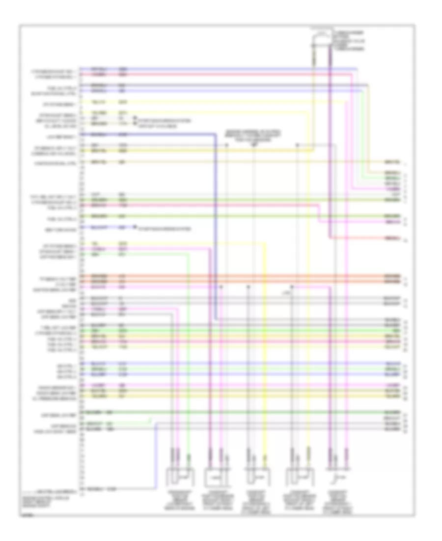
2.8L Turbo, Engine Performance Wiring Diagram (6 of 6) for Saab 9-5 Aero 2011
List of elements for 2.8L Turbo, Engine Performance Wiring Diagram (6 of 6) for Saab 9-5 Aero 2011:
- (engine harness, between fuse block - underhood & g120)
- (engine harness, in formed conduit by throttle body)
- (info not available)
- (top of transmission) transmission control module
- A/c comp clutch rly ctrl
- A/c pres sens 5 volt ref
- A/c refrgnt pres sens lo ref
- A/c refrigerant sens sig
- Acc/run/crank ign 0 volt
- Accelerator pedal position sensor (on pedal bracket)
- Air conditioning system
- Air inj rp rly coil ctrl
- Air inj rpp sens sig
- App 5 volt ref 1
- App 5 volt ref 2
- App low ref 1
- App low ref 2
- App sens sig 1
- App sens sig 2
- Batt pos volt
- Body control module (left end of dash)
- Chk eng ind ctrl
- Computer data lines system
- Coolant temp sens sig
- Cooling fans system
- Cruise control system
- Cruise/etc/tcc brk sig
- Engine control module (right rear of engine compt)
- Engine coolant temperature sensor (right rear of engine)
- Engine main rly coil ctrl
- Evap canister vent sol ctrl
- Exterior lights system
- Fuel pump prm rly ctrl
- G121 (right side of engine)
- Gnd
- Gnd sig
- Hi spd cool fan rly ctrl
- Hi spd gmlan ser data + 1
- Hi spd gmlan ser data - 1
- Ho2s hi sig b 1 s 1
- Ho2s hi sig b 1 s 2
- Ho2s htr lo ctrl b 1 s 1
- Ho2s htr low ctrl b 1 s 2
- Ho2s low b 1 s 2
- Ign
- Ign ctrl 2
- Ign ctrl 4
- Ign ctrl 6
- J113
- J117
- J126
- Knock sens low ref 1
- Knock sens sig 2
- Logic
- Low ref
- Low spd cool fan rly ctrl
- Maf sens sig
- Map sens 5 volt ref
- Mfld air temp sens sig
- P/n pos sw park sig
- Prm fuel level sens sig
- Pwtr main rly f sply 1
- Reverse sw sig
- Run/crank ign 1 volt
- Sec fuel level sens sig
- Starter rly coil ctrl
- Starting/charging system
- Throttle body
- Tp sens sig 1
- Tp sens sig 2
- Transmissions system
- X108
- X200
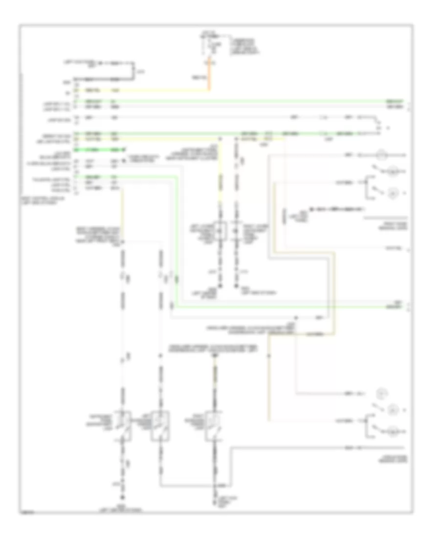
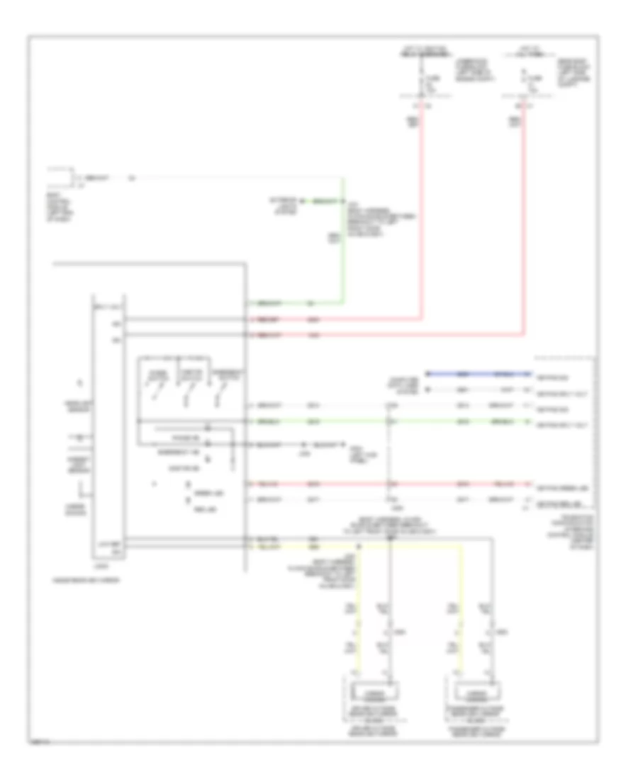
EXTERIOR LIGHTS
Backup Lamps Wiring Diagram for Saab 9-5 Aero 2011
List of elements for Backup Lamps Wiring Diagram for Saab 9-5 Aero 2011:
- (body harness, in main bundle between breakout to left front door inline & g201) j241
- (front of transmission) backup lamp switch
- (or 1796)
- 2.0l
- 2.8l
- Backup lp ctrl
- Backup lp sply volt
- Backup nca
- Body control module (left end of dash)
- Computer data lines system
- Engine control module (right rear of engine compt)
- Fuse 32 20a
- G120 (engine compartment, below engine control module)
- G206 (left center of dash)
- G306 (right side of luggage compt)
- G401 (left side of luggage compt)
- Gear shift position sensor
- Gnd
- Hot at all times
- Inside rearview mirror
- J120
- J216
- J400
- J409
- Left backup lamp
- Left tail lamp assembly
- Logic
- Lp ctrl
- Park/neutral sig
- Rearview mirror
- Right backup lamp
- Right tail lamp assembly
- Rw sw sig
- Serial data(+)
- Serial data(-)
- Sply volt
- Tan
- Transmission control module (a/t)
- Underhood fuse block (left side of engine compt)
- X411
Exterior Lamps Wiring Diagram (1 of 2) for Saab 9-5 Aero 2011
List of elements for Exterior Lamps Wiring Diagram (1 of 2) for Saab 9-5 Aero 2011:
- (body harness, in main bundle between breakout to left front door inline & left bulkhead grommet) j227
- (on brake pedal bracket) brake pedal position sensor
- Ambient light sens sig
- Auto
- Backup lp sply volt sig
- Body control module (left side of dash)
- Center high mounted stop lamp
- Fuse 30a
- G102 (engine compt, on right strut tower)
- G109 (engine compt, on left strut tower)
- G203 (left end of dash)
- G206 (left center of dash)
- G302 (right
- G306 (right rear of luggage compt)
- G401 (left side of luggage compt)
- Haz sw left turn sig
- Haz sw right turn sig
- Haz sw sig
- Hazard led dimming sig
- Head
- Headlamp sw on sig
- Headlamp sw park lp sig
- Headlamp switch
- Headlamps off sig ctrl
- Hot at all times
- Instrument panel multi-function switch
- J104
- J135
- J216
- J220
- J235 (body harness, in branch to body control module, near breakout to left front door inline)
- J400
- J609
- J900
- Kick panel)
- Left
- Left prk lp sply volt
- Lf turn sig lp sply volt
- Lo ref
- Lr stop lp sply volt
- Lr turn sig lp sply volt
- Off
- Park
- Passenger outside rearview mirror
- Rear license lp sply volt
- Rf turn sig lp sply volt
- Right
- Right front side marker lamp
- Right front turn signal lamp
- Right headlamp
- Right prk lp sply volt
- Right rear side marker lamp
- Right rear turn signal lamp
- Right stop lamp
- Right tail lamp assembly
- Right turn signal repeater lamp
- Rr stop lp sply volt
- Sp lp rly coil sply volt
- Turn signal/ multi-function switch
- Underhood fuse block (left side of engine compt)
- X1 center tail lamp
- X101
- X411
- X500
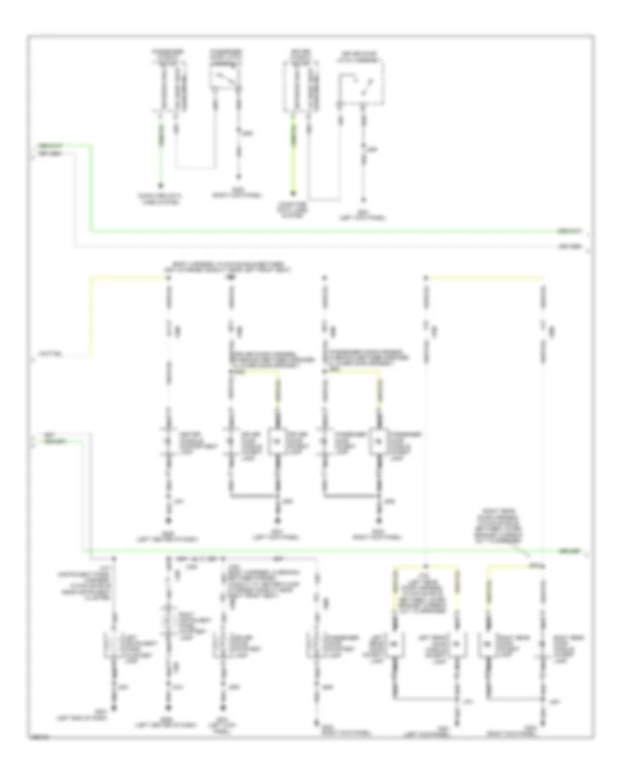
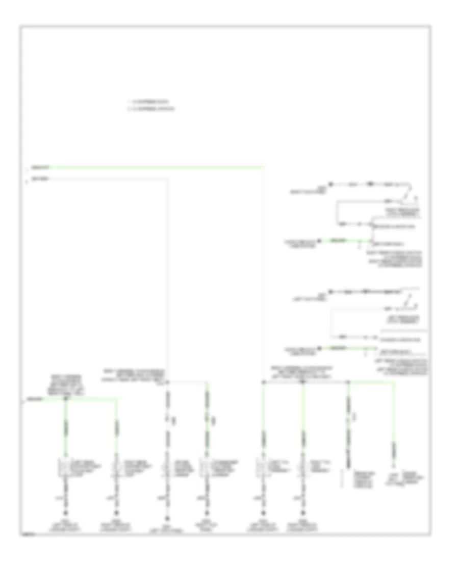
Exterior Lamps Wiring Diagram (2 of 2) for Saab 9-5 Aero 2011
List of elements for Exterior Lamps Wiring Diagram (2 of 2) for Saab 9-5 Aero 2011:
- (body harness, in main bundle between breakout to left front door inline & left bulkhead grommet) j230
- (left side of luggage compt) g401
- Air conditioning system
- Ambient light/sunload sensor (top center of dash)
- Computer data lines system
- Driver outside rearview mirror
- G102 (engine compt, on right strut tower)
- G109 (engine compt, on left strut tower)
- G201 (left kick panel)
- Instrument cluster
- J104
- J135
- J204 (instrument panel harness, on branch leading to remote control door lock receiver)
- J234 (body harness, in branch to body control module, near breakout to left front door inline)
- J409
- J509
- J900
- Left front side marker lamp
- Left front turn signal lamp
- Left headlamp
- Left license plate lamp
- Left rear side marker lamp
- Left rear turn signal lamp
- Left stop lamp
- Left tail lamp assembly
- Left turn ind
- Left turn signal repeater lamp
- Logic
- Park light ind
- Right turn ind
- Serial data
- X1 right license plate lamp x2
- X101
- X411
- X500
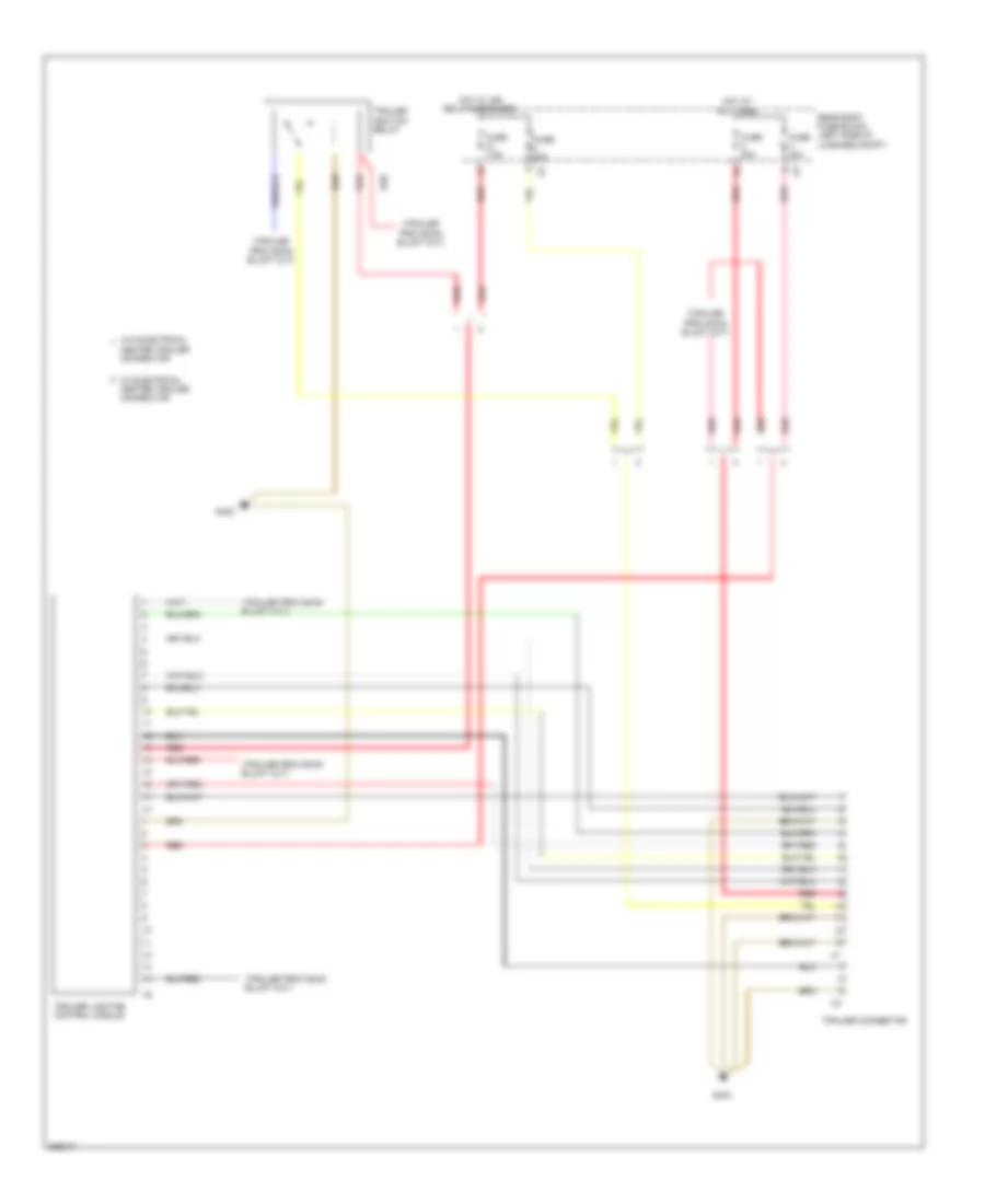
Trailer Tow Wiring Diagram for Saab 9-5 Aero 2011
List of elements for Trailer Tow Wiring Diagram for Saab 9-5 Aero 2011:
- Center trailer connector
- Fuse 20a
- Fuse 40a
- Fuse 7.5a
- G403
- Hot at all times
- Hot w/ ign relay energized
- Rear body fuse block (left side of luggage compt)
- Red
- Trailer connector
- Trailer ignition relay
- Trailer lighting control module
- W/ electrical center trailer connector
- W/o electrical
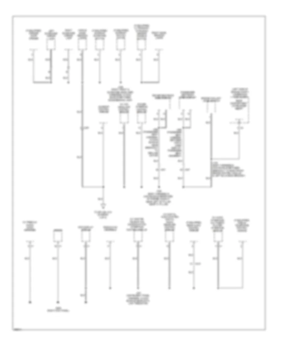
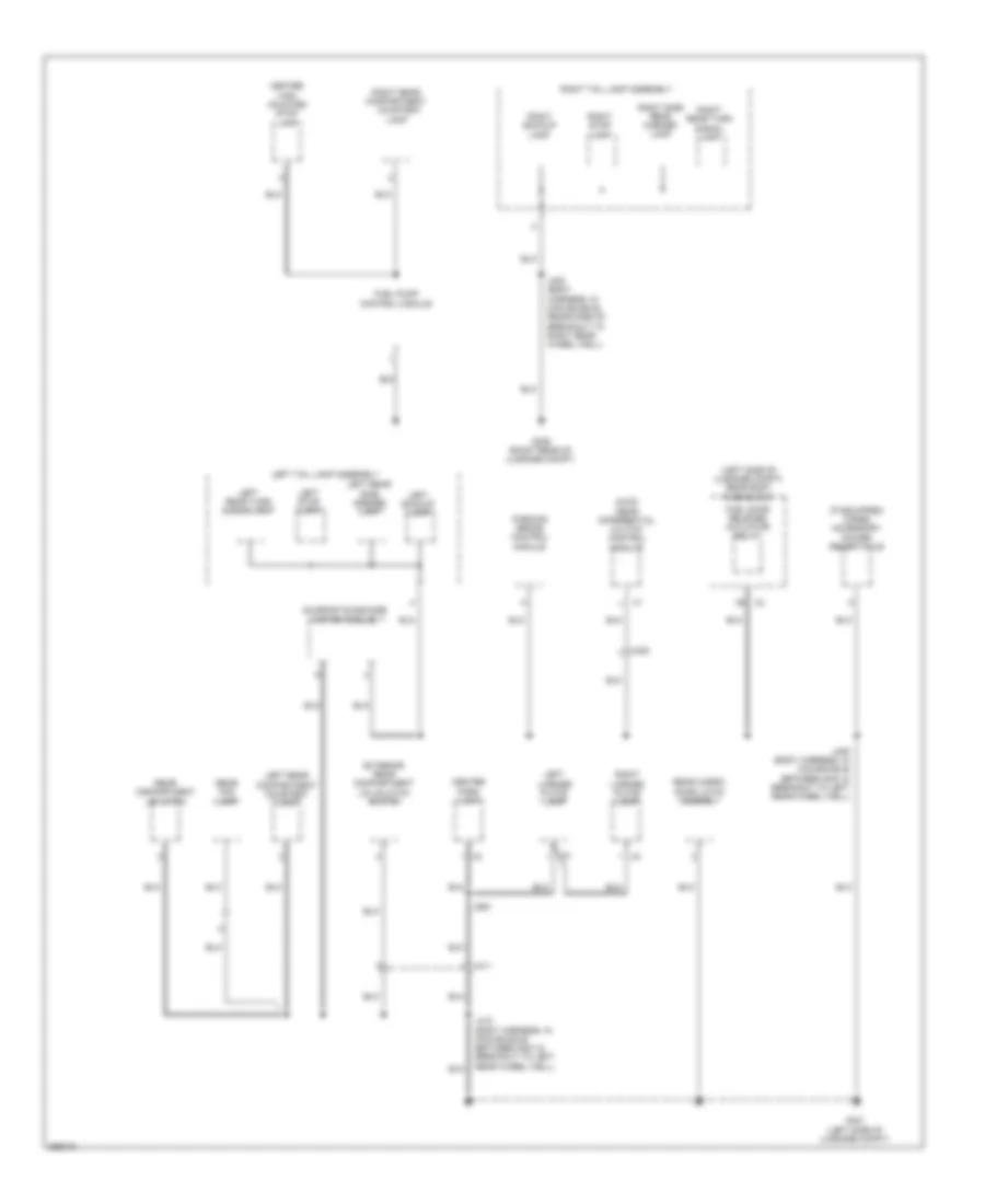
GROUND DISTRIBUTION
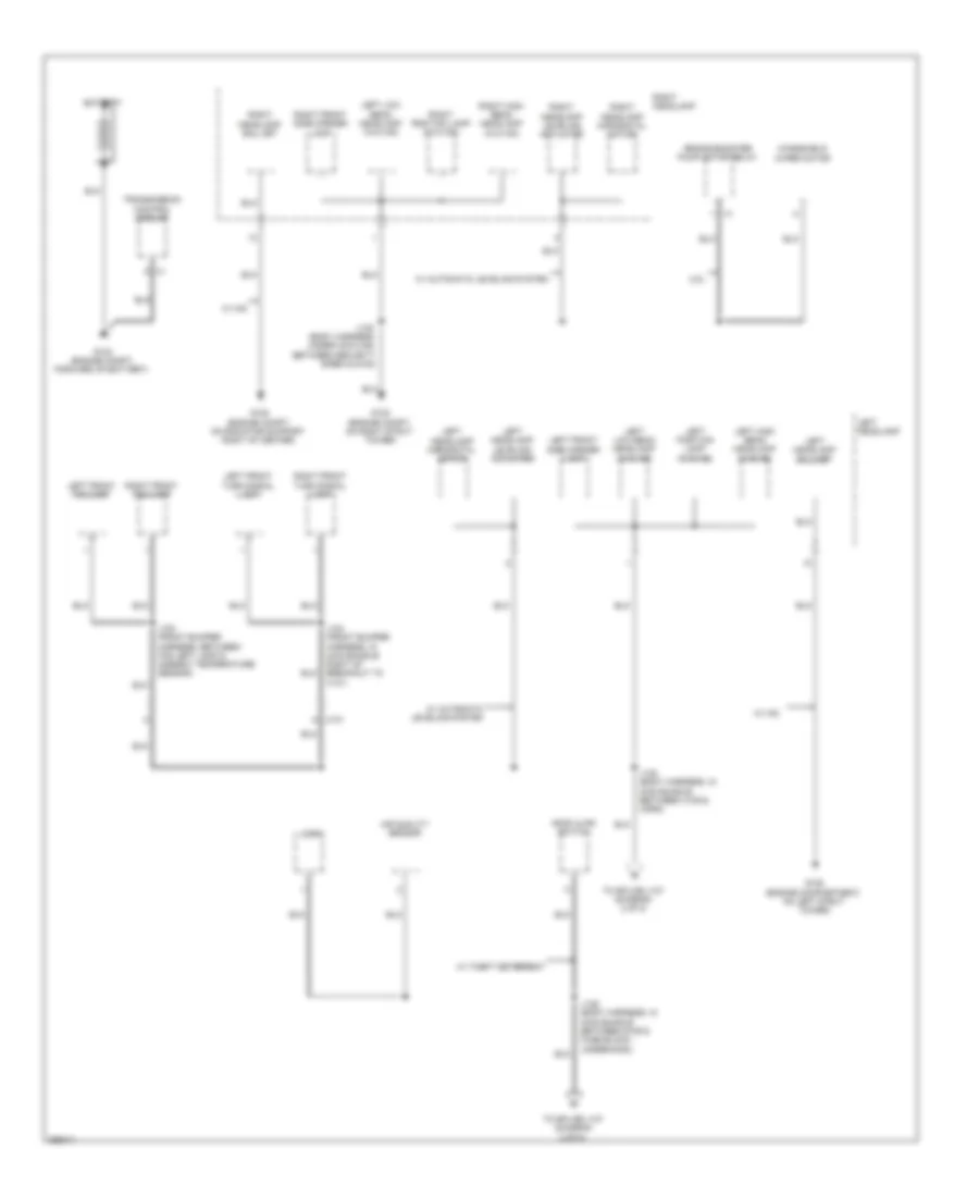
Ground Distribution Wiring Diagram (1 of 8) for Saab 9-5 Aero 2011
List of elements for Ground Distribution Wiring Diagram (1 of 8) for Saab 9-5 Aero 2011:
- 2.8l
- Air quality sensor
- Battery
- Brake booster pump motor relay
- G102 (engine compt, on right strut tower)
- G103 (engine compt, forward of battery)
- G105 (engine compartment, on left strut tower)
- G108 (engine compt, on radiator support right of center)
- Hood ajar switch
- Horn
- J100 (front bumper harness, between fog left lamp & ambient temperature sensor)
- J104 (front bumper harness, in main bundle right of breakout to x101)
- J135 (body harness, under cowling, between security siren & g102)
- J136 (body harness, in main bundle between g109 & fuse block - underhood)
- J138 (body harness, in main bundle between x109 & horn)
- Left front fog lamp
- Left front side marker lamp
- Left front turn signal lamp
- Left headlamp
- Left headlamp ballast
- Left headlamp horizontal motor
- Left headlamp leveling actuator
- Left high beam headlamp (w/o hid)
- Left low beam headlamp (w/o hid)
- Left position lamp (w/o hid)
- N x101
- Right front fog lamp
- Right front side marker lamp
- Right front turn signal lamp
- Right headlamp
- Right headlamp ballast
- Right headlamp horizontal motor
- Right headlamp leveling actuator
- Right high beam headlamp (w/o hid)
- Right position lamp (w/o hid)
- To splice j137 (diagram 2 of 8)
- Transmission control module
- W/ automatic leveling system
- W/ hid
- W/ theft deterrent
- Windshield wiper motor
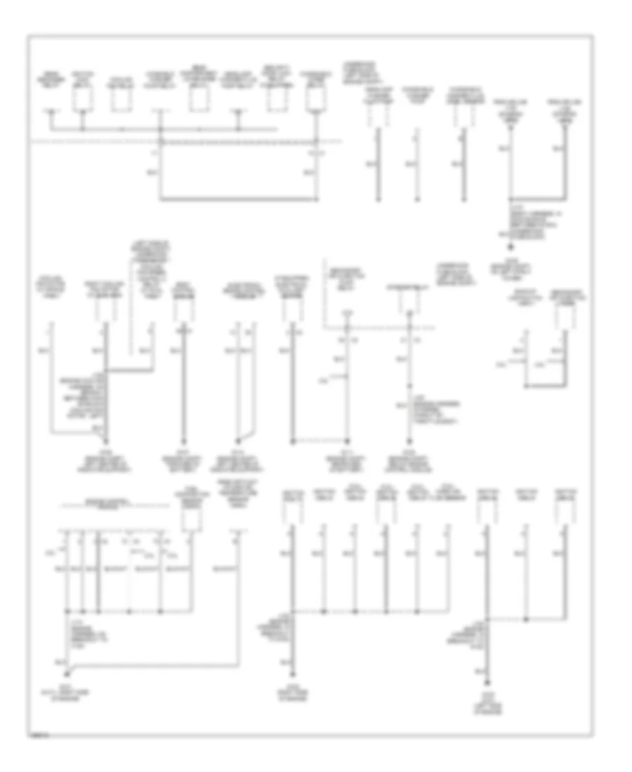
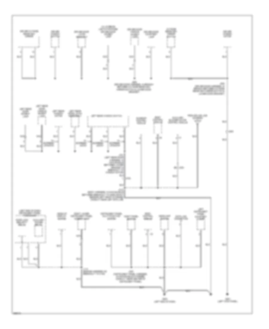
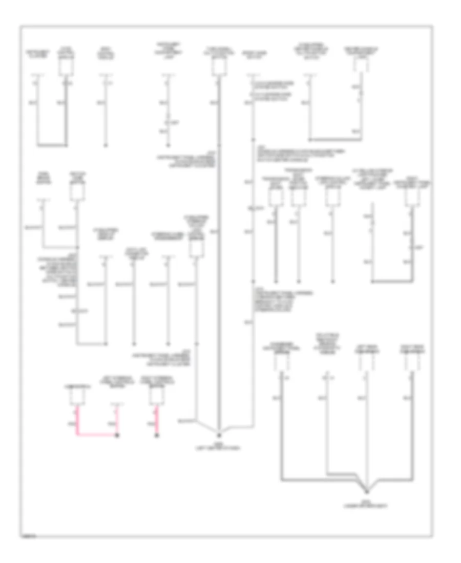
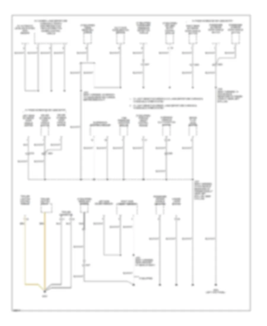
Ground Distribution Wiring Diagram (2 of 8) for Saab 9-5 Aero 2011
List of elements for Ground Distribution Wiring Diagram (2 of 8) for Saab 9-5 Aero 2011:
- (2.0l) ignition coil 2
- (2.0l) ignition coil 4
- (2.8l) ignition coil 5
- (2.8l) mass air flow sensor
- (if equipped) electrical auxiliary heater
- (left side of engine compt) underhood fuse block
- 2.0l
- 2.8l
- 87a
- Backup lamp switch (m/t)
- Body control module
- Cooling fan motor (w/ single fan)
- Cooling fan relay
- Cooling fan speed control 2 relay (w/ dual fan)
- Electronic brake control module
- Engine control module
- From splice j136 (diagram 1 of 8)
- From splice j138 (diagram 1 of 8)
- Fuel composition sensor (2.0l)
- G106 (engine compt, left center of radiator support)
- G107 (engine compt, forward of battery)
- G109 (engine compt, on left strut tower)
- G110 (engine compt, left center of radiator support)
- G111 (engine compt, rearward of battery)
- G120 (engine compt, below engine control module)
- G121 (6 cyl: right side of engine)
- G122 (right side of engine)
- G123 (2.8l) (left side of engine)
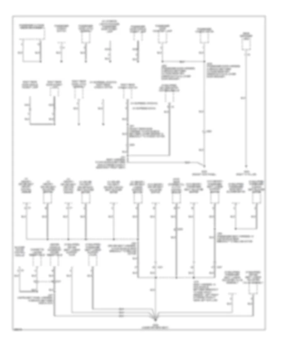
- Headlamp washer fluid pump
- Headlamp washer fluid pump relay
- Ignition coil 1
- Ignition coil 2
- Ignition coil 3
- Ignition coil 4
- Ignition coil 6
- Ignition main relay
- J108 (engine cooling harness, on branch, between main bundle & cooling fan motor - left)
- J113 (engine harness, on breakout to x108)
- J120 (engine harness, in formed conduit by throttle body)
- J122 (engine harness, in breakout to g122)
- J123 (engine harness, in breakout to g123)
- Mass air flow/ intake air temperature sensor (2.0l)
- Rear compartment lid release relay
- Rear defogger relay
- Right cooling fan motor (w/ dual fan)
- Secondary air injection pump
- Secondary air injection pump relay
- Security door lock relay (if equipped)
- Starter relay
- Underhood fuse block (left side of engine compt)
- Windshield washer fluid level sensor
- Windshield washer pump
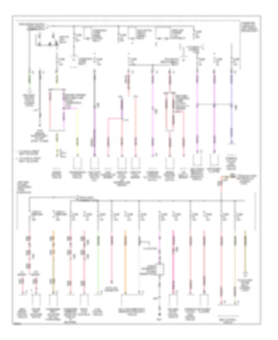
- Windshield wiper relay
- Winshield washer pump relay
Ground Distribution Wiring Diagram (3 of 8) for Saab 9-5 Aero 2011
List of elements for Ground Distribution Wiring Diagram (3 of 8) for Saab 9-5 Aero 2011:
- (left end of dash) instrument panel fuse block
- (w/ interior lights package) driver door accent lamp
- Auxiliary blower motor control module
- Auxiliary power relay
- Body control module
- Data link connector
- Door lock security relay
- Driver door courtesy lamp
- Driver door handle accent lamp
- Driver door latch assembly
- Driver outside rearview mirror
- Driver window motor
- Driver window switch
- From splice j336 (diagram 4 of 8)
- G201 (left kick panel)
- G203 (left end of dash)
- Head-up display switch
- Headlamp switch
- Instrument panel multi-function switch
- J113 (engine harness, on breakout to x108)
- J220 (instrument panel harness, in main bundle in formed conduit, near center of instrument panel)
- J318 (body harness, in main bundle between breakout to side impact sensor-left front & formed conduit near left b-pillar)
- J505 (driver door harness, in branch between outside rearview mirror switch & lower door grommet)
- J509 (driver door harness, in branch between outside rearview mirror switch & lower door grommet)
- J701 (left rear door harness, in main bundle between lower grommet & breakout to window motor)
- Left instrument panel courtesy lamp
- Left rear door accent lamp
- Left rear door handle accent lamp
- Left rear door latch assembely
- Left rear window motor
- Left rear window switch
- Nca
- Night panel switch
- Outside rearview mirror switch
- Right lower instrument panel accent lamp
- Sunroof control module
- W/ express down
- W/ express up/down
- X300 b9
- X500
- X700
Ground Distribution Wiring Diagram (4 of 8) for Saab 9-5 Aero 2011
List of elements for Ground Distribution Wiring Diagram (4 of 8) for Saab 9-5 Aero 2011:
- (if equipped)
- (if equipped) garage door opener
- (if equipped) mobile telephone control module
- (if equipped) rear audio control module
- (if equipped) sunroof sunshade switch
- (if equipped) ultrasonic intrusion sensor disable switch
- (left side of engine compt) underhood fuse block
- (w/ audio interface) multimedia player interface module
- (w/ digital audio system) digital radio receiver control module
- (w/ hid) headlamp control module
- (w/ onstar) telematics communication interface control module
- (w/ premium audio) audio amplifier
- Driver seatback video display
- Engine coolant level switch
- Front dome/ reading lamps
- G205 (right kick panel)
- Info display module
- J140 (body harness,in main bundle between breakout to electronic brake control module & left bulkhead grommet)
- J201 (instrument panel harness, in main bundle near data link tresistor)
- J336 (body harness,in main bundle rearward of formed conduit near left "b" pillar near "c" pillar)
- J346 (right front & sunshade headliner hareness, in main bundle between dome/reading lamp)
- J356 (passenger seat harness, in main bundle near breakout to recline motor)
- J366 (passenger seat harness, between x302 & video display- passenger seat headrest)
- Left sunshade mirror lamp
- Middle dome/ reading lamps
- Nca
- Passenger seatback video display
- Power steering control module
- Radio
- Radio/hvac controls
- Rear compartment lid release relay
- Right sunshade mirror lamp
- Sunroof control module
- Sunroof switch motor
- To splice j318 (diagram 3 of 8)
- X210
- X301
- X307
- X397
Ground Distribution Wiring Diagram (5 of 8) for Saab 9-5 Aero 2011
List of elements for Ground Distribution Wiring Diagram (5 of 8) for Saab 9-5 Aero 2011:
- (if equipped) center console multifunction switch
- (if equipped) head-up display
- (if equipped) steering column lock control module
- (w/ deluxe interior lamp package) left lower instrument panel accent lamp
- (w/ flexride mode system switch)
- (w/o flexride mode system switch)
- Body control module
- Center console compartment lamp
- Data link connector module
- G206 (left center of dash)
- G303 (under driver's seat)
- Horn switch
- Hvac control module
- Ignition mode switch
- Inflatable restraint sensing & diagnostic module
- Instrument cluster
- Instrument panel compartment lamp
- J210 (instrument panel harness, in branch between breakout to hvac control module & steering column)
- J215 (instrument panel harness, in main bundle near instrument cluster)
- J216 (instrument panel harness, in main bundle near instrument clkuster)
- J301 (console harness,in main bundle between ignition mode switch & multifunction switch-center console)
- J304 (console harness, in main bundle between ignition mode switch & multifunction switch - center console)
- Left rear side air bag
- Left steering wheel controls switch
- Nca
- Park brake switch
- Passenger instrument panel air bag
- Pnk
- Right instrument panel courtesy lamp
- Right rear side air bag
- Right steering wheel controls switch
- Sport mode switch
- Steering column lock control module
- Steering wheel angle sensor
- Transmission shift lever
- Transmission shift lever position indicator
- Turn signal/ multi-function switch
- X207
- X210
Ground Distribution Wiring Diagram (6 of 8) for Saab 9-5 Aero 2011
List of elements for Ground Distribution Wiring Diagram (6 of 8) for Saab 9-5 Aero 2011:
- (awd) rear differential clutch control module
- (if equipped) driver seat lumbar adjuster valve assembly
- (if equipped) driver seat lumbar support pump
- (if equipped) keyless entry control module
- (if equipped) passenger back seat blower motor
- (if equipped) passenger cushion seat blower motor
- (if equipped) passenger seat lumbar adjuster valve assembly
- (if equipped) passenger seat lumbar support pump
- (w/ driver fan seat) driver back seat blower motor
- (w/ driver fan seat) driver cushion seat blower motor
- (w/ express down)
- (w/ express up/down)
- (w/ express up/down) right rear window motor
- (w/ interior lights package) passenger door accent lamp
- (w/ memory) driver seat adjuster switch
- (w/ memory) driver seat heating control module
- (w/ memory) driver seat lumbar support switch
- (w/ memory) driver seat memory control module
- (w/o memory) driver seat adjuster switch
- (w/o memory) passenger seat adjuster switch
- (w/o memory) passenger seat lumbar support switch
- Blower motor control module
- Center console accessory power receptacle
- Cigarette lighter receptacle
- G302 (righgt kick panel)
- G305 (under driver's seat)
- G404 (right "c" pillar)
- J207 (instrument panel harness, in branch between g305 & x210)
- J319 (body harness, in main bundle between breakout to side impact sensor - left front & formed conduit near left b-pillar)
- J341 (body harness, in main bundle between g302 & formed conduit near right front seat)
- J354 (driver seat harness, in main bundle near breakout to recline motor)
- J364 (passenger seat harness, in main bundle near breakout to recline motor)
- J605 (passenger door harness, in branch between outside rearview mirror switch & lower door grommet)
- J609 (passenger door harness, in branch between outside rearview mirror switch & lower door grommet)
- J801 (rihght rear door harness, in main bundle between lower grommet & breakout to window motor)
- Nca
- Passenger door courtesy lamp
- Passenger door handle accent lamp
- Passenger door latch assembly
- Passenger outside rearview mirror
- Passenger window motor
- Passenger window switch
- Rear defogger grid
- Right rear door accent lamp
- Right rear door handle accent lamp
- Right rear door latch assembly
- Right rear window switch
- X1 a
- X1 e
- X210
- X301
- X307
- X408 e
- X600
- X800
Ground Distribution Wiring Diagram (7 of 8) for Saab 9-5 Aero 2011
List of elements for Ground Distribution Wiring Diagram (7 of 8) for Saab 9-5 Aero 2011:
- (if equipped) inside rearview mirror
- (if equipped) keyless entry control module
- (if equipped) parking assist control module
- (if equipped) passenger presence detection module
- (if equipped) rearview camera
- (w/ automatic leveling system) rain sensor
- (w/ camera lane departure warning & traffic sign recognition) vehicle direction camera control module
- Brake fluid level switch
- Driver exterior door handle switch
- Driver interior door handle switch
- G304 (left kick panel)
- G403
- Hazard lamps switch
- If equipped
- J244 (body harness, on branch to inside rearview mirror, before breakout)
- J335 (body harness, in main bundle rearward of formed conduit near left b-pillar)
- J337 (body harness, in main bundle rearward of formed conduit near left b-pillar, near c-pillar)
- J403 (body harness, near grommet at rear of body)
- Left rear exterior door handle switch
- Left side object sensor
- Multi-axis acceleration sensor
- Nca
- Overhead console multi-function switch
- Passenger air bag disable indicator
- Passenger exterior door handle switch
- Passenger interior door handle switch
- Right rear exterior door handle switch
- Right side object sensor
- Suspension control module
- Tire pressure indicator module
- Trailer connector
- Trailer ignition relay
- Trailer lighting control module
- W/ light sensitive mirror & w/o lane departure warning & windshield wiper system
- W/ light sensitive mirror, lane departure warning & windshield wiper system
- W/ passive remote keyless entry
- X307
- X398
- X407
- X500
- X600
- X700
- X800
Ground Distribution Wiring Diagram (8 of 8) for Saab 9-5 Aero 2011
List of elements for Ground Distribution Wiring Diagram (8 of 8) for Saab 9-5 Aero 2011:
- (awd) rear differential clutch control module
- (if equipped) cargo accessory power receptacle
- (left side of luggage compt) rear body fuse block
- Center high mounted stop lamp
- Center park lamp
- Courtesy lamp
- Exterior rear compartment lid unlatch switch
- Fuel door release actuator relay
- Fuel pump control module
- G306 (rihgt rear of luggage compt)
- G401 (left side of luggage compt)
- J400 (body harness, in main bundle rearward of breakout to right rear wheel well)
- J409 (body harness, in main bundle between g401 & breakout to left rear wheel well)
- J410 (body harness, in main bundle between g401 & breakout to left rear wheel well)
- J900
- L x408
- Left backup lamp
- Left license plate lamp
- Left rear compartment courtesy lamp
- Left rear side marker lamp
- Left rear turn signal lamp
- Left stop lamp
- Left tail lamp assembly
- Parking brake control module
- Rear cargo door latch assembly
- Rear compartment lid latch
- Rear fog lamp
- Right backup lamp
- Right license plate lamp
- Right rear compartment
- Right rear turn signal lamp
- Right side rear marker lamp
- Right stop lamp
- Right tail lamp assembly
- Sunroof sunshade motor module
- X411
HEADLIGHTS
Headlamps Wiring Diagram, with High Intensity Discharge (1 of 2) for Saab 9-5 Aero 2011
List of elements for Headlamps Wiring Diagram, with High Intensity Discharge (1 of 2) for Saab 9-5 Aero 2011:
- (engine compt, on left strut tower) g105
- (engine compt, on left strut tower) g109
- (engine compt, on radiator support right of center) g108
- (engine compt, on right strut tower) g102
- Air conditioning system
- Ambient light sens sig
- Ambient light/ sunload sensor (a/t) (top center of dash)
- Body control module left end of dash)
- Computer data lines system
- Dim sw
- Fog lamp rly ctrl
- Front fog lamp relay
- Ftp
- Fuse 10a
- Fuse 15a
- Fuse 30a
- G206 (left center of dash)
- Ground
- Hdlp dimmer sw hi beam sig x3
- Hdlp hi beam rly ctrl
- Hdlp lw beam rly ctrl
- Hdlp off sig ctrl
- Hdlp sw flash
- Hdlp sw on sig
- Hdlp sw park lp sig
- Headlamp high beam relay
- Headlamp low beam relay
- Hi spd gmlan ser data+
- Hi spd gmlan ser data-
- Hot at all times
- Hvac control module (center of dash)
- Instrument panel fuse block (left end of dash)
- J101 (front bumper harness, between fog left lamp & ambient temperature sensor)
- J135
- J138
- J204 (instrument panel harness, on branch leading to remote control door lock receiver)
- J216
- Left headlamp
- Left headlamp ballast
- Left high beam headlamp
- Left low beam headlamp
- Left position headlamp
- Lh park lamp sply v
- Lighting ctrl sw ref
- Lighting ctrl sw sig
- Low
- Low ref
- Nca
- Rear fog lamp rly ctrl
- Rh park lamp sply v
- Right headlamp
- Right headlamp ballast
- Right high beam headlamp
- Right low beam headlamp
- Right position headlamp
- To pass sig
- Turn signal/ multi-function switch
- Underhood fuse block (left side of engine compt)
- X101
- X110
- X120
Headlamps Wiring Diagram, with High Intensity Discharge (2 of 2) for Saab 9-5 Aero 2011
List of elements for Headlamps Wiring Diagram, with High Intensity Discharge (2 of 2) for Saab 9-5 Aero 2011:
- Auto
- Battery fuse block (left rear of engine compt)
- Computer data lines system
- Cruise control & sound systems
- Dimmer switch
- Fog lamp switch
- Front fog lamp ind
- Fuse 250a
- Fuse 5a
- G109 (engine compt, on left strut tower)
- G203 (left end of dash)
- G206 (left center of dash)
- G401 (left side of luggage compt)
- Ground
- Head
- Headlamp switch
- High beam lamp ind
- High spd gmlan ser data (+)
- High spd gmlan ser data (-)
- Hot at all times
- Hot w/ ignition main relay energized
- Ign
- Instrument cluster
- J100
- J211 (instrument panel harness, in branch leading to steering column)
- J216
- J220
- J410
- Left front fog lamp
- Logic
- Low spd gmlan ser data
- Off
- Park
- Park brake control switch
- Park brk release sw sig
- Park brk release sw vol ref
- Park brk sw sply volt
- Parking brake control module
- Prk brk sw sig
- Rear fog lamp
- Rear lamp fog switch
- Right front fog lamp
- Underhood fuse block (left side of engine compt)
- X200
- X300
Headlamps Wiring Diagram, without High Intensity Discharge for Saab 9-5 Aero 2011
List of elements for Headlamps Wiring Diagram, without High Intensity Discharge for Saab 9-5 Aero 2011:
- (engine compt, on left strut tower) g109
- (engine compt, on right strut tower) g102
- (front bumper harness, between fog left lamp & ambient temperature sensor) j101
- Air conditioning system
- Ambient light sens sig
- Ambient light/ sunload sensor (a/t) (top center of dash)
- Auto
- Battery fuse block (left rear of engine compt)
- Body control module (left end of dash)
- Computer data lines system
- Cruise control & sound systems
- Dimmer switch
- Driver infor- mation center display
- Fog lamp rly ctrl
- Fog lamp switch
- Front fog lamp ind
- Front fog lamp relay
- Ftp
- Fuse 10a
- Fuse 15a
- Fuse 250a
- Fuse 5a
- G109 (engine compt, on left strut tower)
- G203 (left end of dash)
- G206 (left center of dash)
- G401 (left side of luggage compt)
- Gnd
- Ground
- Hdlp dimmer sw hi beam sig
- Hdlp hi beam rly ctrl
- Hdlp off sig ctrl
- Hdlp sw flash to pass sig
- Hdlp sw on sig
- Hdlp sw park lp sig
- Head
- Headlamp high beam relay
- Headlamp switch
- Hi spd gmlan ser data+
- Hi spd gmlan ser data-
- High
- High beam lamp ind
- Hot at all times
- Hot w/ ignition main relay energized
- Hvac control module (center of dash)
- Ign
- Instrument cluster
- Instrument panel fuse block (left end of dash)
- J100
- J135
- J138
- J201 (instrument panel harness, in main bundle near data link resistor)
- J211 (instrument panel harness, in branch leading to steering column)
- J216
- J220
- J410
- Left front fog lamp
- Left headlamp
- Left high beam headlamp
- Left low beam headlamp
- Lh hdlp lw beam sply volt
- Lighting ctrl sw ref
- Lighting ctrl sw sig
- Logic
- Low
- Low ref
- Low spd gmlan ser data
- Nca
- Off
- Off head
- Park
- Rear fog lamp
- Rear fog lamp rly ctrl
- Rear lamp fog switch
- Rh hdlp lw beam sply volt
- Right front fog lamp
- Right headlamp
- Right high beam headlamp
- Right low beam headlamp
- Turn signal/ multi-function switch
- Underhood fuse block (left side of engine compt)
- X110
- X120
- X200
Headlamps Leveling Wiring Diagram for Saab 9-5 Aero 2011
List of elements for Headlamps Leveling Wiring Diagram for Saab 9-5 Aero 2011:
- (engine compt, on left strut tower) g109
- Body control module (bcm) (left end of dash)
- Computer data lines system
- Front headlamp leveling sensor (left front wheelwell)
- Fuse 15a
- Fuse 5a
- G102 (engine compt, on right strut tower)
- G109 (engine compt, on left strut tower)
- Gmlan ser data +
- Gmlan ser data -
- Headlamp control module (left end of dash)
- Hot at all times
- Hot w/ ignition main relay energized
- J132 (body harness, under cowling, between windshield wiper motor & air quality sensor)
- J135
- J138
- Left headlamp
- Left headlamp horizontal motor
- Left headlamp leveling actuator
- Logic
- Rear headlamp leveling sensor (left rear wheelwell)
- Right headlamp
- Right headlamp horizontal motor
- Right headlamp leveling actuator
- Underhood fuse block (left side of engine compt)
HORN
Horn Wiring Diagram for Saab 9-5 Aero 2011
List of elements for Horn Wiring Diagram for Saab 9-5 Aero 2011:
- Battery fuse block (left rear of engine compt)
- Body control module (left end of dash)
- Fuse 15a
- Fuse 250a
- G109 (engine compt, on left strut tower)
- G206 (left center of dash)
- Horn (behind left side of grill)
- Horn relay ctrl
- Horn switch
- Hot at all times
- J136
- Pnk
- Red
- Steering wheel air bag coil (top of steering column)
- Underhood fuse block (left side of engine compt)
INSTRUMENT CLUSTER
Head-Up Display Wiring Diagram for Saab 9-5 Aero 2011
List of elements for Head-Up Display Wiring Diagram for Saab 9-5 Aero 2011:
- Computer data lines system
- Fuse 15a
- G206 (left center of dash)
- Ground
- Head-up display
- Head-up display switch
- Hot at all times
- Hud off/ dimming sig
- Hud sw sig
- Image dn
- Image up
- Instrument panel fuse block (left side of engine compt)
- Interior lights system
- J215
- J219
- Lo spd gmlan ser data
- Low reference
Instrument Cluster Wiring Diagram (1 of 2) for Saab 9-5 Aero 2011
List of elements for Instrument Cluster Wiring Diagram (1 of 2) for Saab 9-5 Aero 2011:
- (left center of dash)
- (left center of dash) g206
- Abs ind
- Air bag ind
- Ambient air temperature sensor (behind left side of front bumper)
- Awd ind
- Brake ind
- Brake warning ind
- Charge ind
- Computer data lines system
- Cruise ind
- Dic sw sig
- Driver information center (dic) display
- Engine controls system
- Fluid ind low washer
- Fog lamp ind
- Fuel gauge
- Fuel ind
- Fuse 10a
- Fuse 5a
- G206
- Gauge temperature engine coolant
- Gnd
- High beam ind
- Hot at all times
- Hot w/ ignition main relay energized
- Ign
- Ign 1 volt
- Ind
- Instrument cluster
- Instrument panel fuse block (left end of dash)
- J210
- J216
- Lane departure warning ind
- Left turn ind
- Lights on ind
- Lo washer fluid ind ctrl
- Logic
- Low ref
- Low ref ambient air temp sens sig dic select menu sw sig
- Low tire pressure ind
- Malfunction ind
- Menu
- Oil pressure ind
- Park lamps ind
- Parking assist ind
- Pnk
- Right turn ind
- Seat belt ind
- Security ind
- Serial data
- Set/clr
- Speedometer
- Stability off ind
- Tachometer
- Tcs off ind
- Temperature ind engine coolant
- Traction control
- Transmission shift lever position indicator
- Turn signal/ multi-function switch
- Underhood fuse block (left side of engine compt)
- Wait-to-start ind
- Wiper/washer system
- X101
- X200
Instrument Cluster Wiring Diagram (2 of 2) for Saab 9-5 Aero 2011
List of elements for Instrument Cluster Wiring Diagram (2 of 2) for Saab 9-5 Aero 2011:
- (body harness, in main bundle forward of breakout to right rear wheel well)
- (in formed conduit near g123)
- (left side of luggage compt)
- (lower left rear of engine compt) electronic brake control module
- (on brake fluid reservoir) brake fluid level switch
- 2.0l turbo
- 2.8l
- 5-volt ref
- Body control module (left end of dash)
- Brake fluid level sens sig
- Bus 3 network
- Computer data lines system
- Driver door latch assembly
- Driver window motor
- Engine control module (right rear of engine compt)
- Engine controls system
- Engine oil pressure sensor (2.8l) (lower left front of engine)
- Engine oil pressure switch (2.0l turbo) (rear left side of engine)
- Fuel level sens sig
- Fuel pump & level sensor assembly
- G201 (left kick panel)
- G203 (left end of dash)
- G302 (right kick panel)
- G304 (left kick panel)
- G401
- Gmlan serial +
- Gmlan serial -
- Gnd
- Hi gmlan +2
- Hi gmlan -2
- High spd gmlan serial data bus +
- J127 (in formed conduit near g123)
- J128
- J208
- J220
- J337
- J401
- J402
- J509
- J609
- J701
- J801
- Left rear door latch assembly
- Left rear window motor (w/ express up/down) left rear window switch (w/ express down)
- Lf door ajar sw sig
- Lift gate ajar sw sig
- Lr door ajar sw sig
- Network bus 3
- Network bus 4
- Oil pres sw
- Oil press sen sig
- Passenger door latch assembly
- Passenger window motor
- Power distribution system
- Primary
- Rear cargo door latch assembly
- Rf door ajar sw sig
- Right rear door latch assembly
- Right rear window motor (w/ express up/down) right rear window switch (w/ express down)
- Rr door ajar sw sig
- Sec fuel level
- Secondary fuel level sensor
- Sens sig
- Signal gnd
- Tan
- W/ express down
- W/ express up/down
- X108
- X1115
- X200
- X403
INTERIOR LIGHTS
Courtesy Lamps Wiring Diagram (1 of 3) for Saab 9-5 Aero 2011
List of elements for Courtesy Lamps Wiring Diagram (1 of 3) for Saab 9-5 Aero 2011:
- (body harness, in main bundle between g201 & formed conduit near left front seat) j306
- (headliner harness, in main bundle between dome/reading lamp - middle & sunshade - left) j348
- (left kick panel) g201
- Body control module (left end of dash)
- Computer data lines system
- Defeat sw sig
- Front dome/ reading lamps
- Fuse 5a
- G201 (left kick panel)
- G203 (left end of dash)
- G206 (left center of dash)
- Gnd
- Hi spd gmlan ser data
- Hot at all times
- Instrument panel compartment lamp
- J113
- J210
- J212 (instrument panel harness, in main bundle near instrument cluster)
- J216
- J318
- J346
- J349 (headliner harness, in main bundle between dome/reading lamp - middle & x397)
- Lamp ctrl
- Lamp sply vol
- Lamp sw sig
- Led lighting ctrl
- Left lower instrument panel accent lamp
- Left sunshade mirror lamp
- Low spd gmlan ser data
- Middle dome/ reading lamps
- Nca
- Pwr ctrl
- Right lower instrument panel accent lamp
- Right sunshade mirror lamp
- Tailgate lamp ctrl
- Underhood fuse block (left side of engine compt)
- X200
- X207
- X322
- X397
Courtesy Lamps Wiring Diagram (2 of 3) for Saab 9-5 Aero 2011
List of elements for Courtesy Lamps Wiring Diagram (2 of 3) for Saab 9-5 Aero 2011:
- (body harness, in main bundle between g201 & formed conduit near left front seat) j305
- (driver door harness, in branch between speaker & lower door grommet) j502
- (right rear door harness, in main bundle between lower grommet & break out to speaker)
- Ajar sw sig lh front door
- Ajar sw sig rh front door
- B11
- Center console compartment lamp
- Computer data lines system
- Driver door accent lamp
- Driver door courtesy lamp
- Driver door handle accent lamp
- Driver door latch assembly
- Driver window motor
- G201 (left kick panel)
- G203 (left end of dash)
- G206 (left center of dash)
- G302 (right kick panel)
- J210
- J214 (instrument panel harness, in main bundle near instrument cluster)
- J220
- J301
- J345 (body harness, in branch between formed conduit at center floor & formed conduit near right front seat) x500
- J509
- J602
- J609
- J701
- J702 (left rear door harness, in main bundle between lower grommet & break out to speaker)
- J801
- J802
- Left instrument panel courtesy lamp
- Left rear door accent lamp
- Left rear door handle accent lamp
- Nca
- Network bus 3
- Passenger door accent lamp
- Passenger door courtesy lamp
- Passenger door handle accent lamp
- Passenger door latch assembly
- Passenger window motor
- Right instrument panel courtesy lamp
- Right rear door accent lamp
- Right rear door handle accent lamp
- X200
- X207
- X300
- X500
- X600
- X700
- X800
Courtesy Lamps Wiring Diagram (3 of 3) for Saab 9-5 Aero 2011
List of elements for Courtesy Lamps Wiring Diagram (3 of 3) for Saab 9-5 Aero 2011:
- (body harness, in main bundle between breakout to left front door inline & g201) j241
- (body harness, in main bundle between g201 & formed conduit near left front seat) j310
- (body harness, in main bundle between g401 & breakout to left rear wheel well) j411
- Computer data lines system
- Driver outside rearview mirror
- G201 (left kick panel)
- G302 (right kick panel)
- G306 (right rear of luggage compt)
- G401 (left side of luggage compt)
- Inside rearview mirror
- J400
- J409
- J410
- J509
- J609
- J701
- J801
- Lamp sply voltage
- Left rear compartment courtesy lamp
- Left rear door latch assembly
- Left rear window switch (w/ express down) left rear window motor (w/ express up/down)
- Left tail lamp assembly
- Lr door ajar sw sig
- Nca
- Network bus 4
- Passenger outside rearview mirror
- Rearview camera (rear of vehicle)
- Right rear compartment courtesy lamp
- Right rear door latch assembly
- Right rear window switch (w/ express down) right rear window motor (w/ express up/down)
- Right tail lamp assembly
- Rr door ajar sw sig
- W/ express down
- W/ express up/down
- X411
- X500
- X600
Instrument Illumination Wiring Diagram (1 of 2) for Saab 9-5 Aero 2011
List of elements for Instrument Illumination Wiring Diagram (1 of 2) for Saab 9-5 Aero 2011:
- (console harness, in main bundle between ignition mode switch & multifunction switch- center console)
- Between breakout to side impact sensor- left front & formed conduit near left front seat)
- Body control module (left end of dash)
- Center console multi- function switch
- Child lockout ind
- Computer data lines system
- Cruise control system
- Dimm ctrl
- Dimmer sw +
- Dimmer sw -
- Flexride mode system switch
- Front dome/reading lamps
- Front fog lp sw
- Fuse 30a
- G201 (left kick panel)
- G206 (left center of dash)
- G302 (right kick panel)
- Garage door opener
- Gmlan serial data +
- Gmlan serial data -
- Headlamp switch
- Hot at all times
- Ind dimm ctrl
- Instrument panel fuse block (left end of dash)
- Instrument panel multi- function switch
- J211 (instrument panel harness, in branch leading to steering column)
- J301
- J302
- J346
- J347 (headliner harness, in main bundle between dome/reading lamp - front & sunshade - left)
- J509
- J609
- J701
- J801
- Led dimm ctrl
- Left rear window switch
- Lighting ctrl sw ref
- Lighting ctrl sw sig
- Logic
- Lp sw rear fog
- Outside rearview mirror switch
- Passenger window switch
- Right rear window switch
- Sply vol sig
- Sport mode switch
- Sunroof sunshade switch
- Sunroof switch
- Ultrasonic intrusion sensor disable switch
- W/ express up/down
- W/ flexride mode system switch w/o parking aid & lane departure warning
- W/ parking aid & lane departure warning w/o
- W/ parking aid, lane departure warning & flexride mode system switch
- X210
- X397
- X500
- X600
- X700
- X800
Instrument Illumination Wiring Diagram (2 of 2) for Saab 9-5 Aero 2011
List of elements for Instrument Illumination Wiring Diagram (2 of 2) for Saab 9-5 Aero 2011:
- (instrument panel harness, in main bundle in formed conduit, near center of instrument panel) j221
- Cigarette lighter receptacle
- Computer data lines system
- G203 (left end of dash)
- G206 (left center of dash)
- G305 (under driver's seat)
- Head-up display switch
- Headlamp switch
- Instrument cluster
- J113
- J207
- J220
- J301
- J303
- J304
- Left steering wheel controls switch
- Logic
- Multi- function center console switch module
- Multi- function instrument panel switch
- Night panel switch
- Park brake switch (under center console)
- Pnk
- Right steering wheel controls switch
- Sport mode switch
- Steering wheel air bag coil (top of steering column) x3
- System switch
- W/ flexride mode system switch
- W/o flexride mode
- X210
MEMORY SYSTEMS
Memory Mirrors Wiring Diagram (1 of 2) for Saab 9-5 Aero 2011
List of elements for Memory Mirrors Wiring Diagram (1 of 2) for Saab 9-5 Aero 2011:
- Common ctrl
- Defogger system
- Down
- Driver outside rearview mirror folding motor
- Driver outside rearview mirror glass
- Driver outside rearview mirror motor
- Driver outside rearview mirror switch
- Folding switch
- Fuse 7.5a
- G201 (left kick panel)
- Gnd
- Hot w/ ignition relay energized
- Ign
- Interconnect bus 8
- J508
- J515
- Left
- Logic
- Low ref
- Mirror dimming
- Mirror system
- Motor fold in ctrl
- Motor fold out ctrl
- Nca
- Outside rearview mirror switch
- Power windows system
- Right
- Rt (+) lt (-) ctrl
- Sel left
- Sel right
- Underhood fuse block (left side of engine compt)
- Up (+) down (-) ctrl
- X500
Memory Mirrors Wiring Diagram (2 of 2) for Saab 9-5 Aero 2011
List of elements for Memory Mirrors Wiring Diagram (2 of 2) for Saab 9-5 Aero 2011:
- Computer data lines system
- Defogger system
- G302 (right kick panel)
- J609
- J615
- Logic
- Mirror dimming
- Mirror system
- Passenger outside rearview mirror folding motor
- Passenger outside rearview mirror glass
- Passenger outside rearview mirror motor
- Passenger outside rearview mirror switch
- Passenger window switch
- X600
Memory Seat Wiring Diagram (1 of 2) for Saab 9-5 Aero 2011
List of elements for Memory Seat Wiring Diagram (1 of 2) for Saab 9-5 Aero 2011:
- (under driver's seat) g305
- Computer data lines system
- Driver back seat heating element
- Driver front seat vertical motor (under driver seat)
- Driver memory seat switch
- Driver rear seat vertical motor (under driver seat)
- Driver seat cushion heating element
- Driver seat memory control module (under driver's seat)
- Fuse 13 circuit breaker 25a
- Fuse 5a
- Hot at all times
- Instrument panel fuse block (left end of dash)
- J354
- Passenger back seat heating element
- Passenger seat cushion heating element
- Set
- X200
- X301
- X307
Memory Seat Wiring Diagram (2 of 2) for Saab 9-5 Aero 2011
List of elements for Memory Seat Wiring Diagram (2 of 2) for Saab 9-5 Aero 2011:
- (driver's front seat back) driver lumbar seat support horizontal motor
- (driver's front seat back) driver lumbar seat support vertical motor
- (not used)
- Computer data lines system
- Down
- Driver seat adjuster switch
- Driver seat horizontal motor (under driver seat back)
- Driver seat lumbar support switch
- Driver seat memory control module (under driver's seat)
- Driver seat recline motor (under driver seat back)
- Fwd
- G305
- G305 (under driver's seat)
- J319
- J351
- J354
- Rwd
- Seats system
- X301
NAVIGATION
Blind Spot Monitoring Wiring Diagram for Saab 9-5 Aero 2011
List of elements for Blind Spot Monitoring Wiring Diagram for Saab 9-5 Aero 2011:
- Backup lp sply volt x7
- Body control module (left end of dash)
- Camera drain wire
- Camera sig +
- Camera sig -
- Camera sig 2
- Camera sig 2+
- Exterior lights system
- Fuse 53 10a
- G304 (left kick panel)
- Ground
- Hot w/ ignition run relay energized
- Ign volt 1
- J241 (body harness, in main bundle between breakout to left front door inline & g201)
- J416
- J903
- Nca
- Radio
- Rearview camera (rear of vehicle)
- Sply volt
- Underhood fuse block (left side of engine compt)
- X204
- X407
- X411
Lane Departure Warning Wiring Diagram for Saab 9-5 Aero 2011
List of elements for Lane Departure Warning Wiring Diagram for Saab 9-5 Aero 2011:
- Battery positive voltage
- Computer data lines system
- Driver outside rearview mirror
- Drv side object detection led sig
- Fuse 10a
- G201 (left kick
- G302 (right kick
- G304 (left kick panel)
- Hot at all times
- J403
- J509
- J609
- Left side object sensor
- Low speed gmlan
- Low speed gmlan serial data
- Panel)
- Pass side object detection led sig
- Passenger outside rearview mirror
- Rear body fuse block (left side of luggage compt)
- Right side object sensor
- Sig gnd
- X500
- X600
Navigation Wiring Diagram, with Surround Amplifier (1 of 6) for Saab 9-5 Aero 2011
List of elements for Navigation Wiring Diagram, with Surround Amplifier (1 of 6) for Saab 9-5 Aero 2011:
- (instrument panel harness, on branch leading to info display module)
- (or 5839)
- (or 5843)
- (right kick panel)
- Amplifier ctrl
- Anti-lock brakes system
- Audio common sig
- Audio sig
- Aux audio screen
- Auxiliary audio sig
- Batt+ volt
- Camera sig
- Cellular phone navigation & digital radio antenna (w/ digital system s band)
- Coax
- Computer data lines
- Computer data lines system
- Detection sig
- Display reset sig
- Display sig+
- Display sig-
- Drain wire
- Fuse 10a
- Fuse 15a
- Fuse 20a
- G205
- Gmlan serial -
- Gmlan serial data
- Gmlan serial data +
- Ground
- Hot at all times
- Instrument panel fuse block (left end of dash)
- J205
- J219
- J222
- Lf aud sig
- Lf lo level aud-
- Lf rr seat aud sig
- Lf rr spkr+
- Lf spd sig
- Lines system
- Lo level audio sig
- Lo level audio sig+
- Lo level audio sig-
- Lo level audio-
- Lo refr
- Lo spd gmlan
- Nav+
- Nav-
- Navigation & traffic data antenna
- Navigation antenna
- Navigation system
- Nca
- Radio
- Remote audio
- Remote enable sig
- Rf lo level aud-
- Rh aud sig
- Rh rr seat aud sig
- Rr au drain wire
- Rr spkr sig -
- Satellite radio circuit
- Serial data hi
- Serial data lo
- Shield
- Stack reset sig
- Telephone voice sig
- W/ navigation display
- W/ upj
- W/o navigation display
- W/o upj
- Wake-up sig
- X204
- X207
Navigation Wiring Diagram, with Surround Amplifier (2 of 6) for Saab 9-5 Aero 2011
List of elements for Navigation Wiring Diagram, with Surround Amplifier (2 of 6) for Saab 9-5 Aero 2011:
- (right kick panel)
- (w/ gid) info display module
- A14
- A15
- Aud sig
- Audio sig
- B14
- B15
- Batt pos volt
- Batt+
- Batt+ volt
- Cellular phone antenna
- Coax
- Comm sig
- Computer data lines system
- Data hi
- Data lo
- Data sh
- Drain wire
- G205
- Gnd
- Ground
- Ir aud sig
- J201
- Lo refr
- Logic
- Lr aud sig
- Mobile telephone control module (center of dash)
- Navigation and traffic data antenna
- Nca
- Net bus
- Net- bus 9
- Radio antenna
- Radio antenna module (on right "c" pillar)
- Radio/hvac control
- Rear audio control module
- Reset sig
- Rr aud sig
- Serial data hi
- Serial data lo
- Serial data sh
- Voice sig
- W/ information display, color info display (cid)
- W/ onstar
- W/o information display, color info display (cid)
- W/o onstar
- Wake up sig
- Wake-up sig
- X200
- X208
- X210
- X300
- X301
Navigation Wiring Diagram, with Surround Amplifier (3 of 6) for Saab 9-5 Aero 2011
List of elements for Navigation Wiring Diagram, with Surround Amplifier (3 of 6) for Saab 9-5 Aero 2011:
- (body harness, in main bundle between breakout to side impact sensor left front & formed conduit near left b-pillar)
- (left end of dash) body control module (bcm)
- (right kick panel)
- Amplifier ctrl
- Audio amplifier (right side of luggage compt)
- Batt+ volt
- Computer data lines system
- Cruise control system
- Ctrl sw ref
- Fr center spkr
- Fr center spkr +
- Fr lo level audio
- G205
- Ground
- Hi spd gmlan serial data+
- Hi spd gmlan serial data-
- Interior lights system
- J320
- Lader sig 1
- Left subwoofer speaker
- Lf lo level audio-
- Lf rr speaker +
- Lf speaker +
- Lf speaker sig-
- Lo level audio
- Lo level audio sig
- Lo level audio sig lo level audio sig
- Lo level audio-
- Lr speaker -
- Lr speaker out +
- Lr spkr sig -
- Lr wfr speaker-
- Mute
- Nca
- R speaker out +
- Remote enable sig
- Rf speaker sig-
- Rf spkr +
- Rh rr speaker -
- Rh subufr -
- Right steering wheel control switch
- Right subwoofer speaker
- Rr lo level audio-
- Rr spkr sig -
- Seek down
- Seek up
- Source
- Steering wheel air bag coil (top of steering column)
- Voice
- Vol +
- Vol -
Navigation Wiring Diagram, with Surround Amplifier (4 of 6) for Saab 9-5 Aero 2011
List of elements for Navigation Wiring Diagram, with Surround Amplifier (4 of 6) for Saab 9-5 Aero 2011:
- (body harness, in main bundle between breakout to side impact sensor - left front & formed conduit near left b-pillar)
- (body harness, in main bundle between g302 & formed conduit near right front seat)
- (instrument panel harness, in main bundle near data link resistor)
- (left kick panel) g201
- Batt+ volt
- Bright ctrl
- Driver seatback video display
- Dvd vid sig+
- Dvd vid sig-
- Enable sig
- G201 (left kick panel)
- G205 (right kick panel)
- Gnd
- Info display module (w/ cid & wvga touch screen)
- J201
- J222
- J322
- J342
- J343
- J356
- J366
- Module sig
- Nca
- Nca drain wire
- Nca s
- Passenger seatback video display
- Sig +
- Video sig+
- Video sig-
- X1 sig -
- X204
- X301
- X307
Navigation Wiring Diagram, with Surround Amplifier (5 of 6) for Saab 9-5 Aero 2011
List of elements for Navigation Wiring Diagram, with Surround Amplifier (5 of 6) for Saab 9-5 Aero 2011:
- Aud comm sig
- Aud screen
- Audio com sig
- Audio/video input adapter
- Aux sig
- Auxiliary audio input
- Batt +
- Bright ctrl
- Computer data lines system
- D wire
- Drain wire
- Dvd ado shld
- G205 (right kick panel)
- Gnd
- High sig
- J201
- L spd data
- Lf aud sig
- Lf aud sig 2
- Lf sig 3
- Lh dvd sig +
- Low sig
- Lt audio sig 1
- Mid spd
- Module sig
- Multimedia player interface module (right end of dash)
- Nca
- Radio
- Red
- Rh aud sig
- Rh aud sig 2
- Rh audio sig 1
- Rh sig 3
- Rmt inf sig -
- Sig
- Sig 2
- Sig 3
- Vid sig -
- Video mode 2
- Video sig 2+
- Video sig 2-
- Video sig-
- W/ audio interface
- W/o audio interface
- X204
- X210
- X216
Navigation Wiring Diagram, with Surround Amplifier (6 of 6) for Saab 9-5 Aero 2011
List of elements for Navigation Wiring Diagram, with Surround Amplifier (6 of 6) for Saab 9-5 Aero 2011:
- (driver door harness, in branch between speaker & lower door grommet)
- (passenger door harness, in branch between speaker & lower door grommet)
- Batt + volt
- Batt sply volt
- Cellular phone microphone
- Cellular phone navigation & digital radio antenna
- Center instrument panel speaker
- Coax
- Computer data lines system
- Display color info display
- Fuse 35 30a
- G205 (right kick panel)
- G304 (left kick panel)
- Gnd
- Hot at all times
- Inside rear view mirror
- J201
- J244
- J335
- J503
- J504
- J603
- J604
- Keypad sig
- Left front speaker
- Left front tweeter speaker
- Left rear speaker
- Left surround speaker
- Lo ref
- Lo refr
- Lo spd data
- Logic
- Lp ref
- Micro ph sig
- Navigation antenna signal splitter
- Nca
- Red led
- Right front speaker
- Right front tweeter speaker
- Right rear speaker
- Right surround speaker
- Serial data
- Serial data +
- Serial data -
- Shield
- Sply volt
- Tele voice sig
- Telematics button assembly
- Telematics communication interface control module (w/ onstar) (center of dash)
- Telematics communication interface control module battery
- Underhood fuse block (left side of engine compt)
- Voice aud sig
- W/ infotainment
- W/ light sensitive mirror & w/o lane departure warning & windshield wiper system
- W/ light sensitive mirror, lane departure warning & windshield wiper system
- W/o infotainment display color info display
- X200
- X500
- X600
- X700
- X800
Navigation Wiring Diagram, without Surround Amplifier (1 of 6) for Saab 9-5 Aero 2011
List of elements for Navigation Wiring Diagram, without Surround Amplifier (1 of 6) for Saab 9-5 Aero 2011:
- (right kick panel)
- Amplifier ctrl
- Anti-lock brakes system
- Audio common sig
- Audio sig
- Audio signal (1)
- Aux audio screen
- Auxiliary audio sig
- Batt+ volt
- Camera sig +
- Camera sig -
- Coax
- Computer data lines
- Computer data lines system
- Data wire
- Detection sig
- Display reset sig
- Display sig+
- Display sig-
- Drain wire
- Fr audio drain wire
- Fuse 10a
- Fuse 15a
- Fuse 20a
- G205
- Gmlan serial cata +
- Gmlan serial cata -
- Gmlan serial data
- Ground
- Hot at all times
- Instrument panel fuse block (left end of dash)
- J205
- J219
- J222
- Lf lo level aud-
- Lf rr seat aud sig
- Lf rr spkr+
- Lines system
- Lo level audio sig+
- Lo level audio sig-
- Lo level audio-
- Lo refr
- Lo spd gmlan
- Navi+
- Navi-
- Navigation & traffic data antenna
- Navigation antenna
- Navigation system
- Nca
- Radio
- Radio audio (-)
- Radio lf aud sig
- Remote enable sig
- Rf lo level aud-
- Rh rr seat aud sig
- Right audio sig 2
- Rr au drain wire
- Rr spkr sig -
- Satellite radio circuit
- Serial data hi
- Serial data lo
- Shield
- Speed sensor sig
- Stack reset sig
- Telephone
- Telephone voice sig
- Usb
- W/ cellular
- W/ infotainment display
- W/ infotainment display color info display (cid) w/o onstar
- W/ premium 9 or 7 speaker system
- W/o cellular
- W/o infotainment display
- Wake-up sig
- X204
- X207
Navigation Wiring Diagram, without Surround Amplifier (2 of 6) for Saab 9-5 Aero 2011
List of elements for Navigation Wiring Diagram, without Surround Amplifier (2 of 6) for Saab 9-5 Aero 2011:
- (w/ information display graphic info display (gid)) info display module
- A14
- A15
- Aud sig
- Audio sig
- B14
- B15
- Batt pos volt
- Batt+
- Batt+ volt
- Cellular phone antenna
- Coax
- Comm sig
- Computer data lines system
- Data hi
- Data lo
- Data sh
- Drain wire
- G205 (right kick panel)
- Gnd
- Ground
- J201
- Lo refr
- Logic
- Lr aud sig
- Mobile telephone control module (center of dash)
- Navigation & traffic data antenna
- Nca
- Net bus
- Net- bus 9
- Radio antenna (integral to rear window)
- Radio antenna module (on right "c" pillar)
- Radio/hvac control
- Rear audio control module (if equipped)
- Red aud sig
- Reset sig
- Rr aud sig
- Serial data hi
- Serial data lo
- Serial data sh
- Up sig
- Voice sig
- W/ information display graphic info display (gid)
- W/ onstar
- W/o information display graphic info display (gid)
- W/o onstar
- Wake-up sig
- X200
- X206
- X210
- X300
- X301
Navigation Wiring Diagram, without Surround Amplifier (3 of 6) for Saab 9-5 Aero 2011
List of elements for Navigation Wiring Diagram, without Surround Amplifier (3 of 6) for Saab 9-5 Aero 2011:
- (body harness, in main bundle between breakout to side impact sensor - left front & formed conduit near left b-pillar)
- Body control module (bcm) (left end of dash)
- Computer data lines system
- Cruise control system
- Ctrl sw refr
- Hi spd gmlan serial data+
- Hi spd gmlan serial data-
- Interior lights system
- J320
- Lader sig 1
- Mute
- Nca
- Right steering wheel control switch
- Seek down
- Seek up
- Src
- Steering wheel air bag coil (top of steering column)
- Voice
- Vol +
- Vol -
Navigation Wiring Diagram, without Surround Amplifier (4 of 6) for Saab 9-5 Aero 2011
List of elements for Navigation Wiring Diagram, without Surround Amplifier (4 of 6) for Saab 9-5 Aero 2011:
- (body harness, in main bundle between breakout to side impact sensor)
- (driver door harness, in branch between speaker & lower door grommet)
- (instrument panel harness, in main bundle near data link resistor)
- (instrument panel harness, on branch leading to radio x1)
- (left kick panel) g201
- Batt+ volt
- Bright ctrl
- Driver seatback video display
- Dvd video +
- Dvd video -
- Enable sig
- Enable sig +
- G201 (left kick panel)
- G205 (right kick panel)
- Gnd
- Info display module (w/ infotainment display color info display (cid))
- J201
- J245
- J322
- J323
- J342
- J343
- J356
- J366
- J503 (driver door harness, in branch between speaker & lower door grommet)
- J504
- Left front speaker
- Left front tweeter speaker
- Left rear speaker
- Module sig
- Nca
- Nca drain wire
- Nca s
- Passenger seatback video display
- Right rear speaker
- Video sig+
- Video sig-
- X200
- X204
- X301
- X307
- X500
- X700
- X800
Navigation Wiring Diagram, without Surround Amplifier (5 of 6) for Saab 9-5 Aero 2011
List of elements for Navigation Wiring Diagram, without Surround Amplifier (5 of 6) for Saab 9-5 Aero 2011:
- (instrument panel harness, on branch leading to radio x1)
- (passenger door harness, in branch between speaker & lower door grommet)
- Aud comm sig
- Aud screen
- Audio/video input adapter
- Aux sig
- Auxiliary audio input
- Batt +
- Bright ctrl
- Center console speaker
- Coax
- Computer data lines system
- D wire
- Drain wire
- Fh video sig
- G205 (right kick panel)
- Gnd
- J201
- J246
- J603
- J604
- L spd data
- Lf aud sig
- Lf aud sig 2
- Lf sig 3
- Mid spd
- Module sig
- Multimedia player interface module (right end of dash)
- Nca
- Radio
- Red
- Rh aud sig
- Rh aud sig 2
- Rh sig 3
- Rh video sig
- Right front speaker
- Right front tweeter speaker
- Sig
- Sig 2
- Sig 3
- Video com sig
- Video hi
- Video l
- Video mode 2
- Video sig 2+
- Video sig 2-
- Video sig-
- W/ audio interface
- W/o audio interface
- X200
- X204
- X210
- X216
- X500
Navigation Wiring Diagram, without Surround Amplifier (6 of 6) for Saab 9-5 Aero 2011
List of elements for Navigation Wiring Diagram, without Surround Amplifier (6 of 6) for Saab 9-5 Aero 2011:
- (in overhead console) cellular phone microphone
- Batt + volt
- Batt sply volt
- Cellular phone navigation & digital radio antenna
- Coax
- Computer data
- Computer data lines system
- Display color info display
- G205 (right kick panel)
- G304 (left kick panel)
- Gnd
- Inside rear view mirror
- J201
- J244
- J335
- Keypad sig
- Lo ref
- Lo refr
- Lo spd data
- Logic
- Lp refr
- Micro ph sig
- Navigation antenna signal splitter (right end of dash)
- Nca
- Red led
- Serial data
- Serial data +
- Serial data -
- Shield
- Sply volt
- Tele voice sig
- Telematics button assembly
- Telematics communication interface control module battery
- Telematics communication interface control module w/ onstar (center of dash)
- Voice aud sig
- W/ digital audio system s-band
- W/ infotainment
- W/ light sensitive mirror & w/o lane departure warning & windshield wiper system
- W/ light sensitive mirror, lane departure warning & windshield wiper system
- W/o infotainment display color info display
- X200
Parking Assistant Wiring Diagram for Saab 9-5 Aero 2011
List of elements for Parking Assistant Wiring Diagram for Saab 9-5 Aero 2011:
- (left kick panel)
- Battery pos volt
- Center console multifunction switch
- Computer data lines system
- Front parking left corner sens
- Front parking left mid sens
- Front parking lf/ri/mi sens
- Front parking right corner sens
- Front parking right mid sens
- Fuse 15a
- G206 (left center of dash)
- G304
- Hot at all times
- Instrument panel fuse block (left end of dash)
- J145 (fuel injector even harness, at top of engine, below intake mainfold, in main bundle)
- J146
- J209
- J301
- J337
- J479 (rear bumper harness, in main bundle between rear object sensor - left middle & rear object sensor - right middle)
- J480 (rear bumper harness, in main bundle between rear object sensor - left middle & rear object sensor - right middle)
- Left front parking aid side sensor (on left side of front bumper)
- Left middle front object sensor (behind left side of front bumper)
- Left middle rear object sensor (behind left middle of rear bumper)
- Left outer front object sensor (behind left side of front bumper)
- Left outer rear object sensor (behind left side of rear bumper)
- Lf front supp object sens sig
- Low reference
- Low speed gmlan serial data
- Lr corner object sens sig parallel park assist disable switch sig
- Lr middle object sens sig
- Park assist sensor sply
- Parking assist control module (left side of luggage compt)
- Rear park assist disable signal
- Rear park assist led disable sig
- Rf front supp object sens sig
- Right front parking aid side sensor (on right side of front bumper)
- Right middle front object sensor (behind right side of front bumper)
- Right middle rear object sensor (behind right middle of rear bumper)
- Right outer front object sensor (behind right side of front bumper)
- Right outer rear object sensor (behind right side of rear bumper)
- Rr corner object sens sig
- Rr middle object sens sig
- Sig ground
- X110
- X200
- X406
Rear View Camera Wiring Diagram for Saab 9-5 Aero 2011
List of elements for Rear View Camera Wiring Diagram for Saab 9-5 Aero 2011:
- (above headliner)
- Battery positive voltage
- Center console multi function switch
- Computer data lines system
- Fuse 10a
- G206 (left center of dash)
- G304 (left kick panel)
- Hot at all times
- Instrument cluster
- J244
- J300
- J301
- Lane departure
- Led departure warning disable switch sig
- Led warning indicator control
- Logic
- Low
- Low speed gmlan serial data
- Rear body fuse block (left side of luggage compt)
- Sig gnd
- Spd-
- Vehicle direction camera control module
- Warning ind
- X200
POWER DISTRIBUTION
Power Distribution Wiring Diagram (1 of 6) for Saab 9-5 Aero 2011
List of elements for Power Distribution Wiring Diagram (1 of 6) for Saab 9-5 Aero 2011:
- (2.0l)
- (2.8l)
- (body harness, under cowling, between windshield wiper motor & air quality sensor) j132
- (diagram 2 of 6)
- (in main bundle between breakout to side impact sensor - left front & formed conduit near left front seat)
- (in main bundle between g201 & formed conduit near left front seat)
- (in main bundle between g401 & breakout to left rear wheel well) j416
- (in main bundle near breakout to recline motor) j365
- (left side of engine compt) underhood fuse block
- Battery
- Battery fuse block (left rear of engine compt)
- Driver cushion seat blower motor (w/ fan)
- Driver seat back blower motor (w/ fan)
- Driver seat lumbar support switch (if equipped)
- Driver window motor
- Electrical auxiliary heater
- Electronic brake control module
- Engine control module
- From fuse 52 j
- Fuel pump relay
- Fuse 100a
- Fuse 10a
- Fuse 15a
- Fuse 20a
- Fuse 250a
- Fuse 300a
- Fuse 30a
- Fuse 50a
- Fuse 5a
- Fuse 60a
- Generator
- Inside rear view mirror
- J309
- J316
- J355
- Left headlamp (w/ headlamp leveling)
- Nca
- Parking brake control module
- Passenger cushion seat blower motor (w/ fan)
- Passenger seat back blower motor (w/ fan)
- Passenger seat lumbar support switch (if equipped)
- Passenger window motor
- Power steering control module
- Rearview camera
- Recline motor)
- Red
- Right headlamp (w/ headlamp leveling)
- Secondary air injection pump relay (2.8l) fuse/ heater relay (2.0l)
- Starter motor
- Starter relay
- Tire pressure indicator module
- To auxiliary underhood fuse block (diagram 5 of 6)
- To fuse 32 (diagram 5 of 6)
- To instrument panel fuse block (diagram 2 of 6)
- To instrument panel fuse block (diagram 4 of 6)
- To rear body fuse block (diagram 5 of 6)
- Transmission control module
- Used) (not
- W/ light sensitive mirror
- W/ rearview camera
- W/ tire pressure indicator
- W/ tire pressure indicator, light sensitive mirror & rear view camera
- X110
- X120
- X200
- X301
- X307
- X407
- X500
- X600
Power Distribution Wiring Diagram (2 of 6) for Saab 9-5 Aero 2011
List of elements for Power Distribution Wiring Diagram (2 of 6) for Saab 9-5 Aero 2011:
- (2.0l) x1
- (2.8l) x2
- (between windshield wiper motor & air quality sensor)
- (engine harness, between fuse block - underhood & g120)
- (left end of dash) instrument panel fuse block
- 2.0l
- 2.8l
- 87a
- A/t
- Air quality sensor
- Body control module
- Brake booster vacuum switch
- Cargo accessory power receptacle
- Circuit breaker 25a
- Cooling fan medium speed 1 relay
- Cooling fan medium speed 2 relay
- Data link connector
- Driver seat adjuster switch
- Engine control module
- From battery fuse block (diagram 1 of 6)
- From body control module (diagram 6 of 6)
- From engine control module relay g (diagram 3 of 6)
- From fuse 9 (diagram 4 of 6)
- Fuel composition sensor
- Fuel pump control module (2.8l)
- Fuse 10a
- Fuse 15a
- Fuse 20a
- Fuse 25a
- Fuse 30a
- Fuse 5a
- Fuse 60a
- Fuse 7.5a
- G109 (engine compartment, on left strut tower)
- G401
- Headlamp washer fluid pump relay
- Hvac control module
- Ignition main relay
- Inflatable restraint sensing & diagnostic module
- Instrument cluster
- J114
- J118
- J131
- J137
- J409
- Keyless entry control module
- M/t
- Mass air flow sensor
- Mass air flow/ intake air temperature sensor
- Overhead console multifunction switch
- Passenger presence detection module (if equipped)
- Passenger seat adjuster switch (if equipped)
- Radio/ hvac controls
- Red/
- Seat adjuster
- Seat memory control module
- Steering column lock control module
- To auxiliary power relay (diagram 4 of 6)
- To fuse 54 (diagram 1 of 6)
- Transmission control module
- Underhood fuse block (left side of engine compt)
- W/ manual front seat adjuster
- W/ memory
- W/ on star
- W/o manual front
- W/o memory
- Windshield wiper relay
- Windshield wiper speed control relay
- X108
- X200
- X301
- X307
- X398
Power Distribution Wiring Diagram (3 of 6) for Saab 9-5 Aero 2011
List of elements for Power Distribution Wiring Diagram (3 of 6) for Saab 9-5 Aero 2011:
- (2.0l)
- (2.8l)
- (at top of engine, below intake manifold, in main bundle)
- (engine harness, in formed conduit by throttle body) j119
- (engine harness, in formed conduit near g123)
- (not used)
- 2.0l
- 2.8l
- A/c compr- essor clutch relay
- Cooling fan high speed relay
- Cooling fan left medium speed relay
- Cooling fan medium speed 1 relay
- Cooling fan medium speed 2 relay
- Cooling fan relay
- Cooling fan right medium speed relay
- Cooling fan speed control 2 relay
- Cooling fan speed control relay
- Engine control module
- Engine control module relay
- From fuse 46 l (diagram 3 of 6)
- From fuse 70 f (diagram 5 of 6)
- Front fog lamp relay
- Fuel injector
- Fuse 10a
- Fuse 15a
- Fuse 60a 30a
- Headlamp high beam relay
- Headlamp low beam relay
- Ignition coil 1
- Ignition coil 2
- Ignition coil 2 (2.8l)
- Ignition coil 3
- Ignition coil 4
- Ignition coil 4 (2.8l)
- Ignition coil 5
- Ignition coil 6 (2.8l)
- J106 (between main bundle & relay block - underhood)
- J120 (in formed conduit by throttle body)
- J121
- J144
- Rear defogger relay
- Rear window washer pump relay
- Right cooling fan medium speed relay
- To fuse 11 (diagram 6 of 6)
- To fuse 9 (diagram 3 of 6)
- To ignition main relay (diagram 2 of 6)
- Underhood fuse block (left side of engine compt)
- Underhood relay block
- Underhood relay block (left side of engine compt)
- W/ dual fan
- W/ hid
- W/ single fan
- Windshield washer pump relay
- X117
- X160 (fuel injector even harness, at top of engine, below intake manifold, in main bundle) j145
Power Distribution Wiring Diagram (4 of 6) for Saab 9-5 Aero 2011
List of elements for Power Distribution Wiring Diagram (4 of 6) for Saab 9-5 Aero 2011:
- (if equipped)
- (in branch between breakout to hvac control module & steering column)
- (in main bundle near data link resistor)
- (in main bundle rearward of formed conduit near left "b" pillar) j323
- (instrument panel harness, in main bundle in formed conduit, near center of instrument panel) j219
- (left end of dash)
- A/t
- Auxiliary power relay
- Block - instrument panel)
- Blower motor control module
- Body control module
- Center console accessory power receptacle
- Cigarette lighter receptacle
- Digital radio receiver control module
- Driver seatback video display (if equipped)
- Entertainment package
- From battery fuse block (diagram 1 of 6)
- From fuse 24 (diagram 2 of 6)
- Fuse 10a
- Fuse 15a
- Fuse 20a
- Fuse 25a
- Fuse 30a
- Fuse 50a
- G203
- G305
- Head-up display (w/ rearview camera)
- Info display module (if equipped)
- Instrument panel fuse block
- Instrument panel fuse block (left end of dash)
- Interior lights system
- J113
- J208
- J222
- J223 (in main bundle near fuse block - instrument panel)
- J224 (in main bundle near fuse block - instrument panel)
- J248
- M/t
- Mobile telephone control module (w/ wireless interface)
- Multimedia player interface module
- Parking assist control module
- Passenger seatback video display (if equipped)
- Radio
- Radio/ hvac controls (w/ info- tainment display)
- Rear audio control module (if equipped)
- Security siren (if equipped)
- To circuit breaker 12 (diagram 2 of 5)
- Transmission shift lever
- W/ rear seat
- W/o rear seat
- X200
- X200 (body harness, in main bundle rearward of formed conduit near left b-pillar, near c-pillar) j338
- X204
- X210
- X301
- X307
Power Distribution Wiring Diagram (5 of 6) for Saab 9-5 Aero 2011
List of elements for Power Distribution Wiring Diagram (5 of 6) for Saab 9-5 Aero 2011:
- (if equipped)
- (in branch between window switch - driver & lower door grommet) j508
- (in main bundle between g201 & formed conduit near left front seat) j307
- (in main bundle rearward of formed conduit near left b-pillar, near c-pillar) j340
- (left side of luggage compt) underhood fuse block
- 2.0l
- 2.8l
- Audio amplifier
- Auxiliary blower motor control module (w/ rear fan)
- Auxiliary electrical heater
- Auxiliary underhood fuse block
- Body control module
- Brake booster pump motor
- Cruise control vehicle distance sensor module (if equipped)
- Driver window switch
- Evaporative emission vent solenoid valve
- Express down
- Express up/down
- Formed conduit at center floor & formed conduit near right front seat) j344
- From battery fuse block (diagram 1 of 6)
- From battery fuse block e (diagram 1 of 6)
- From fuse 27 (diagram 1 of 6)
- From underhood fuse block (diagram 1 of 6)
- Fuel pump control module
- Fuse 100a
- Fuse 10a
- Fuse 20a
- Fuse 25a
- Fuse 30a
- Fuse 5a
- Fuse 60a
- Fuse 7.5a
- Fuse 80a
- Garage door opener
- Glow plug control module (2.0l)
- Headlamp control module
- Horn relay
- Inside rearview mirror
- Keyless entry control module
- Keyless entry control module (2.8l)
- Left rear window motor
- Left rear window switch
- Left side object sensor (if equipped)
- Outside rearview mirror switch
- Overhead console multi- function switch
- Passenger window switch
- Rain sensor
- Rear body fuse block (left side of engine compt)
- Rear differential clutch control module (awd)
- Rear wiper relay
- Right rear window motor
- Right rear window switch
- Right side object sensor (if equipped)
- Seat heating control module
- Sun roof motor
- Sunroof sunshade motor module (if equipped)
- Suspension control module (w/ continuously variable real time damping)
- To engine control module relay (diagram 3 of 6)
- Underhood relay block
- Vehicle direction camera control module (if equipped)
- X117
- X12
- X300
- X301
- X397
- X403
- X408
- X500
- X600
- X700
- X800
Power Distribution Wiring Diagram (6 of 6) for Saab 9-5 Aero 2011
List of elements for Power Distribution Wiring Diagram (6 of 6) for Saab 9-5 Aero 2011:
- (engine harness, between fuse block - underhood & g120) j117
- (engine harness, in branch between g120 & main bundle) j129
- (engine harness, in formed conduit by throttle body) j120
- (engine harness, in formed conduit near g123)
- (left side of engine compartment) underhood fuse block
- 2.0l
- 2.8l
- A10
- A12
- Accy
- B12
- Body control module (left end of dash)
- Engine control module
- Engine start/ stop
- Evaporative emission purge solenoid valve
- Exhaust camshaft position actuator solenoid valve bank 1
- Exhaust camshaft position actuator solenoid valve bank 2
- From fuse 8 (diagram 3 of 6)
- Fuse 10a
- Fuse 15a
- G206 (left center of dash)
- Heated oxygen sensor 1
- Heated oxygen sensor 1 bank 1
- Heated oxygen sensor 2
- Heated oxygen sensor 2 bank 1
- Ign mode sw acc led sig
- Ign mode sw mode volt
- Ign mode sw off led sig
- Ign mode sw st led sig
- Ignition mode switch
- Intake camshaft position actuator solenoid valve bank 1
- Intake camshaft position actuator solenoid valve bank 2
- J130
- J147
- J211
- Keyless entry control module (right kick panel)
- Low ref
- Nca
- Passive st sw sig 2
- Run/crank ign 1 volt
- Run/crank ign 1 volt x3
- Run/crank rly coil ctrl
- To underhood fuse block (diagram 2 of 6)
- Turbo- charger bypass solenoid valve
- Turbo- charger wastegate solenoid valve
- Turbocharger bypass solenoid valve
- Turbocharger wastegate solenoid valve
- X200
- X210
- X300
POWER DOOR LOCKS
Power Door Locks Wiring Diagram, with Passive Keyless Entry (1 of 3) for Saab 9-5 Aero 2011
List of elements for Power Door Locks Wiring Diagram, with Passive Keyless Entry (1 of 3) for Saab 9-5 Aero 2011:
- (behind center of rear bumper) rear fascla keyless entry antenna
- (center front of luggage compt) rear compartment keyless entry antenna
- (front of center console) center console front keyless entry antenna
- (left end of dash)
- (rear of center console) center console rear keyless entry antenna
- A13
- Acc volt
- Ant 1 sig hi
- Ant 1 sig lo
- Ant 2 sig hi
- Ant 2 sig lo
- Ant 3 sig hi
- Ant 3 sig lo
- Ant sig hi
- Ant sig lo
- B13
- Bat pos volt
- Co drv ant sig lo
- Co drv dr ant sig hi
- Co drv extr sw lk sig
- Co drv handle sw sig
- Co drv mtr unlatch rtn
- Co drv unlatch ctrl
- Computer data lines system
- Driver interior door handle switch
- Drv dr handle sw sig
- Drv mtr unlatch ctrl
- Drv mtr unlatch rtn
- Drv unlatch sig
- Exterior door handle switch
- Fuse 30a
- Fuse 5a
- G302
- G304
- G304 (right kick panel)
- Gnd
- Handle sw sig
- Hot at all times
- Instrument panel fuse block
- J335
- J337
- J341
- Keyless entry control module (right kick panel)
- Left rear
- Lo ref
- Lo spd gmlan ser data
- Lr dr handle sw sig
- Lr mtr unlatch rtn
- Lr unlatch ctrl
- Nca
- Passenger interior door handle switch
- Passive start sw sig 2
- Right rear exterior door handle switch
- Rr closure ant sig hi
- Rr dr handle sw sig
- Rr mtr unlatch ctrl
- Rr mtr unlatch rtn
- Run/crank ign 1 vol
- Shift interlock system
- Sig gnd
- Starting/ charging system
- Steering column lk sig
- Tan
- Underhood fuse block (left side of engine compt)
- X200
- X299
- X500
- X600
- X700
- X800
Power Door Locks Wiring Diagram, with Passive Keyless Entry (2 of 3) for Saab 9-5 Aero 2011
List of elements for Power Door Locks Wiring Diagram, with Passive Keyless Entry (2 of 3) for Saab 9-5 Aero 2011:
- (in driver's door) driver window motor
- (in main bundle between breakout to left front door inline & g201) j233
- (in main bundle between g201 & formed conduit near left front seat) j311
- (in main bundle between g201 & formed conduit near left front seat) j312
- (in passenger's door) passenger window motor
- (left rear door harness, in main bundle between door latch assembly & breakout to window motor) j703
- (left side of engine compt) underhood fuse block
- (right kick
- (right rear door harness, in main bundle between door latch assembly & breakout to window motor) j803
- Door lock security relay
- Driver door latch assembly
- G109 (engine compt, on left strut tower)
- G201 (left kick panel)
- G302
- G302 (right kick panel)
- J314 (in main bundle between breakout to side impact sensor - left front & formed conduit near left front seat)
- J315 (in main bundle between breakout to side impact sensor - left front & formed conduit near left front seat)
- J701
- J801
- Left rear door latch assembly
- Left rear window motor
- Lf dr ajar sw sig
- Lh rr dr ajar sw sig
- Panel)
- Passenger door latch assembly
- Right rear door latch assembly
- Sw sig rf dr ajar
- Tan
- Trunk, tailgate, fuel doors system
- W/ express up/down
- W/ theft deterent body security content
- W/o express down
- W/o theft deterent body security content
- X500
- X600
- X700
- X800
Power Door Locks Wiring Diagram, with Passive Keyless Entry (3 of 3) for Saab 9-5 Aero 2011
List of elements for Power Door Locks Wiring Diagram, with Passive Keyless Entry (3 of 3) for Saab 9-5 Aero 2011:
- (left end of dash) instrument panel fuse block
- (left kick panel) g304
- Acc volt
- Actuator recv sig
- Actuator rtn
- Actuator sply volt
- Actuator transmit sig
- Ajar sw sig rh rr dr
- Bat pos volt
- Body control module (left end of dash)
- Computer data lines system
- Door lock security relay
- Dr acutator lk ctrl 2
- Dr lk ctrl
- Dr unlk ctrl
- Drive exterior door handle assembly
- Driver door handle keyless entry antenna
- Driver exterior door handle switch
- Driver information center display
- Drv dr unlatch sig
- Fuse 5a
- G203
- G203 (left end of dash)
- G304 (left kick panel)
- G401 (left side of luggage compt)
- Gmlan ser data +
- Gmlan ser data -
- Gnd
- Hdlp hi beam rly ctrl
- Headlights system
- Horn relay ctrl
- Horns system
- Hot all times
- Instrument panel cluster (ipc)
- J113
- J220
- J335
- J337
- J410
- Lift gate ajar sw sig
- Lk rey ctrl
- Logic
- Lr security lk mtr sig
- Nca
- Non drv unlatch sig
- Passenger door handle keyless entry antenna
- Passenger exterior door handle assembly
- Passenger exterior door handle switch
- Rear compartment lid latch
- Remote control door lock receiver (above inside rearview mirror)
- Right rear window motor
- Rr security lk mtr sig
- Run/crank ign 1 volt
- Security indicator
- Security lk rly ctrl
- Tan
- Underhood fuse block (left side of engine compt)
- W/ express up/down
- W/o express down
- X200
- X500
- X600
Power Door Locks Wiring Diagram, without Passive Keyless Entry for Saab 9-5 Aero 2011
List of elements for Power Door Locks Wiring Diagram, without Passive Keyless Entry for Saab 9-5 Aero 2011:
- (in main bundle between breakout to side impact sensor lf & formed conduit near lf seat)
- (in main bundle between lower grommet & breakout to speaker) j803
- (left end of dash) g203
- (left end of dash) instrument panel fuse block
- (left side of engine compt) (w/ theft deterent body security content) underhood fuse block
- Actr rtn
- Actr unlck ctrl
- Batt pos volt
- Body control module (left end of dash)
- Center display
- Child lkout ind
- Child lockout security ind
- Computer data lines system
- Door lock security relay
- Dr lck ctrl (2)
- Dr lk ctrl
- Driver
- Driver door latch assembly
- Driver window motor (in driver's door)
- Drv dr lk sw lk sig
- Drv dr lk sw unlk sig
- Fuse 5a
- G109 (engine compt, on left strut tower)
- G201 (left kick panel)
- G203 (left end of dash)
- G302 (right kick panel)
- G401 (left side of luggage compt)
- Gmlan ser data (+)
- Gmlan ser data (-)
- Hdlp hi beam rly ctrl
- Headlights system horns system
- Horn rly ctrl
- Hot at all times
- Information
- Instrument panel cluster (ipc)
- Instrument panel multifunction switch
- Interior lights system
- J113
- J233 (in main bundle between breakout to lf door inline & g201)
- J311 (in main bundle between g201 & formed conduit near lf seat)
- J312 (in main bundle between g201 & formed conduit near lf seat)
- J314 (in main bundle between breakout to side impact sensor - lf & formed conduit near lf seat)
- J315
- J410
- J509
- J609
- J701
- J801
- Left rear door latch assembly
- Lf dr ajar sw sig
- Lk rly ctrl
- Logic
- Lr lk mtr status sig
- Passenger door latch assembly
- Passenger window motor (in passenger's door)
- Rcv sig
- Rear compartment lid latch
- Remo actr sply volt
- Remo actr trans sig
- Remo func actr rtn
- Remote control door lock receiver (above inside rearview mirror)
- Rf dr ajar sw sig
- Right rear door latch assembly
- Rr lk mtr status sig
- Security content
- Security indicator
- Security lk rly ctrl
- Security lk sw sig
- Sply volt
- Trans sig
- Trunk, tailgate, fuel doors system
- Underhood fuse block (left side of engine compt)
- W/ theft deterent body
- W/o theft deterent body
- X200
- X500
- X600
- X700
- X800
POWER MIRRORS
Electrochromic Mirror Wiring Diagram for Saab 9-5 Aero 2011
List of elements for Electrochromic Mirror Wiring Diagram for Saab 9-5 Aero 2011:
- (body harness, in main bundle between breakout to left front door inline & g201) j239
- Ambient light sensor
- Body control module (left end of dash)
- Computer data lines system
- Driver outside rearview mirror
- Driver outside rearview mirror glass
- Emergency ind
- Emergency switch
- Exterior lights system
- Fuse 10a
- G304 (left kick panel)
- Green led
- Headlight sensor
- Hot at all times
- Hot w/ ignition relay energized
- Ign
- Inside rearview mirror
- J240 (body harness, in main bundle between breakout to left front door inline & g201)
- J241 (body harness, in main bundle between breakout to left front door inline & g201)
- J335
- Keypad green led
- Keypad red led
- Keypad sig
- Keypad sply volt
- Logic
- Low ref
- Mirror dimming
- Onstar ind
- Onstar switch
- Passenger outside rearview mirror
- Passenger outside rearview mirror glass
- Phone ind
- Phone switch
- Rear body fuse block (left side of luggage compt)
- Red led
- Sig
- Sply volt
- Telematics communication interface control module (center of dash)
- Underhood fuse block (left side of engine compt)
- X200
- X500
- X600
Power Mirror Wiring Diagram for Saab 9-5 Aero 2011
List of elements for Power Mirror Wiring Diagram for Saab 9-5 Aero 2011:
- Common ctrl
- Computer data lines system
- Defogger system
- Down
- Driver outside rearview mirror
- Driver outside rearview mirror folding motor
- Driver outside rearview mirror motor
- Electrochromic mirror circuit
- Folding switch
- Fuse 7.5a
- G201 (left kick panel)
- Hot w/ ignition relay energized
- Ign
- Interconnect bus 8
- J506 (driver door harness, in branch between outside rearview mirror switch & lower door grommet)
- J507 (driver door harness, in branch between outside rearview mirror switch & lower door grommet)
- J509
- J515 nca
- J615
- Left
- Logic
- Low ref
- Mirror dimming
- Motor fold in ctrl
- Motor fold out ctrl
- Nca
- Outside rearview mirror switch
- Passenger outside rearview mirror
- Passenger outside rearview mirror folding motor
- Passenger outside rearview mirror motor
- Right
- Rt (+) lt (-) ctrl
- Sel left
- Sel right
- Underhood fuse block (left side of engine compt)
- Up (+) down (-) ctrl
- X500
- X600
POWER SEATS
Driver Power Seat Wiring Diagram for Saab 9-5 Aero 2011
List of elements for Driver Power Seat Wiring Diagram for Saab 9-5 Aero 2011:
- Circuit breaker 25a
- Down
- Driver seat adjuster switch
- Driver seat front vertical motor (under driver's front seat)
- Driver seat horizontal motor (under driver's front seat)
- Driver seat rear vertical motor (under driver's front seat)
- Driver seat recline motor (in driver front seat back)
- Fwd
- G305 (under driver's seat)
- Hot at all times
- Instrument panel fuse block (lower left side of dash)
- J319
- Recline fwd
- Recline rwd
- Rwd
- X200
- X301
Driver"s Lumbar Wiring Diagram for Saab 9-5 Aero 2011
List of elements for Driver"s Lumbar Wiring Diagram for Saab 9-5 Aero 2011:
- Down
- Driver seat lumbar adjuster valve assembly
- Driver seat lumbar support pump
- Driver seat lumbar support switch
- Fuse 15a
- Fwd
- G305 (under driver's seat)
- Hot at all times
- J354
- Rwd
- Underhood fuse block (left side of engine compt)
- X301
Heated Seats Wiring Diagram, with Memory for Saab 9-5 Aero 2011
List of elements for Heated Seats Wiring Diagram, with Memory for Saab 9-5 Aero 2011:
- (driver seat harness, in main bundle near breakout to recline motor) j355
- (passenger seat harness, in main bundle near breakout to recline motor) j365
- Circuit breaker 25a
- Computer data lines system
- Driver back seat blower motor
- Driver back seat heating element
- Driver back switch
- Driver cushion seat blower motor
- Driver cushion seat heating element
- Driver cushion switch
- Driver seat memory control module (under driver's seat)
- Fuse 10a
- Fuse 5a
- G305 (under driver's
- G305 (under driver's seat)
- Hot at all times
- Hot w/ ignition main relay energized
- Instrument panel fuse block (left end of dash)
- J350 (driver seat harness, in main bundle near breakout to seat horizontal motor)
- J354
- J360 (passenger seat harness, in main bundle past breakout to anchor pretensioner)
- J364
- Logic
- Main bundle between breakout to side impact sensor - left front & formed conduit near left front seat)
- Passenger back seat blower motor
- Passenger back seat heating element
- Passenger back switch
- Passenger cushion back switch
- Passenger cushion seat blower motor
- Passenger cushion seat heating element
- Radio/hvac controls
- Seat)
- Underhood fuse block (left side of engine compt)
- X200
- X301
- X307
Heated Seats Wiring Diagram, without Memory for Saab 9-5 Aero 2011
List of elements for Heated Seats Wiring Diagram, without Memory for Saab 9-5 Aero 2011:
- (driver seat harness, in main bundle near breakout to recline motor) j355
- (passenger seat harness, in main bundle near breakout to recline motor) j365
- Computer data lines system
- Driver back seat blower motor
- Driver back seat heating element
- Driver back switch
- Driver cushion seat blower motor
- Driver cushion seat heating element
- Driver cushion switch
- Driver seat heating control module (under driver's seat)
- Fuse 10a
- Fuse 25a
- G305 (under driver's
- G305 (under driver's seat)
- Hot w/ ignition main relay energized
- In main bundle between breakout to side impact sensor - left front & formed conduit near left front seat)
- J350 (driver seat harness, in main bundle near breakout to seat horizontal motor)
- J354
- J360 (passenger seat harness, in main bundle past breakout to anchor pretensioner)
- J364
- Logic
- Passenger back seat blower motor
- Passenger back seat heating element
- Passenger back switch
- Passenger cushion back switch
- Passenger cushion seat blower motor
- Passenger cushion seat heating element
- Radio/hvac controls
- Seat)
- Underhood fuse block (left side of engine compt)
- X301
- X307
Passenger Power Seat Wiring Diagram for Saab 9-5 Aero 2011
List of elements for Passenger Power Seat Wiring Diagram for Saab 9-5 Aero 2011:
- Circuit breaker 25a
- Down
- Fwd
- G305 (under driver's seat)
- Hot at all times
- Instrument panel fuse block (left end of dash)
- J319
- Passenger seat adjuster switch
- Passenger seat front vertical motor (under passenger's front seat)
- Passenger seat horizontal motor (under passenger's front seat)
- Passenger seat rear vertical motor (under passenger's front seat)
- Passenger seat recline motor (in passenger front seat back)
- Recline fwd
- Recline rwd
- Rwd
- X200
- X307
Passenger"s Lumbar Wiring Diagram for Saab 9-5 Aero 2011
List of elements for Passenger"s Lumbar Wiring Diagram for Saab 9-5 Aero 2011:
- Down
- Fuse 15a
- Fwd
- G305 (under driver's seat)
- Hot at all times
- J364
- Passenger seat lumbar adjuster valve assembly
- Passenger seat lumbar support pump
- Passenger seat lumbar support switch
- Rwd
- Underhood fuse block (left side of engine compt)
- X307
POWER TOP/SUNROOF
Power Top/Sunroof Wiring Diagram for Saab 9-5 Aero 2011
List of elements for Power Top/Sunroof Wiring Diagram for Saab 9-5 Aero 2011:
- (left kick panel) g201
- (left side of luggage compt) g401
- Batt pos volt
- Close
- Close express
- Computer data lines system
- Express close
- Express open
- Fuse 25a
- Fuse 30a
- G201 (left kick panel)
- G401 (left side of luggage compt)
- Gnd
- Hot at all times
- Interior lights system
- J318
- J336
- J409
- J410
- Lo ref linear interconnect network bus 1 fr sunshade sw sig
- Lo ref linear interconnect network bus 1 sunroof sw data 1
- Logic
- Open
- Open express
- Rear body fuse block (left side of luggage compt)
- Sunroof control module (forward of sunroof)
- Sunroof sunshade motor module (top center rear of roof)
- Sunroof sunshade switch
- Sunroof switch
- Underhood fuse block (left side of engine compt)
- X397
POWER WINDOWS
Power Windows Wiring Diagram, with Express Down (1 of 2) for Saab 9-5 Aero 2011
List of elements for Power Windows Wiring Diagram, with Express Down (1 of 2) for Saab 9-5 Aero 2011:
- (left kick panel)
- Ajar sw sig
- B+ volt
- Computer data lines system
- Door locks system
- Down
- Down sig
- Driver window motor
- Driver window switch
- Express
- Express sig
- Fuse 30a
- Fuse 7.5a
- G201
- G201 (left kick panel)
- G302 (right kick panel)
- Gnd
- Hot at all times
- J309
- J505
- J508
- J509
- J605
- J609
- Lock out ind
- Logic
- Network bus 3
- Passenger window motor
- Passenger window switch
- Underhood fuse block (left side of engine compt)
- Up sig
- Window switch left rear
- Window switch right front
- Window switch right rear
- X500
- X600
Power Windows Wiring Diagram, with Express Down (2 of 2) for Saab 9-5 Aero 2011
List of elements for Power Windows Wiring Diagram, with Express Down (2 of 2) for Saab 9-5 Aero 2011:
- (left kick panel)
- (right kick panel)
- Computer data lines system
- Door locks system
- Down
- Express
- Fuse 21 30a
- G201
- G302
- Gnd
- Hot at all times
- J307
- J701
- Left rear window motor
- Left rear window switch
- Logic
- Lr down ctrl
- Lr dr ajar sw sig
- Lr up ctrl
- N/w bus 4
- Right rear window motor
- Right rear window switch
- Rr down ctrl
- Rr dr ajar sw sig
- Rr up ctrl
- Underhood fuse block (left side of engine compt)
- X700
- X800
Power Windows Wiring Diagram, with Express Up/Down (1 of 2) for Saab 9-5 Aero 2011
List of elements for Power Windows Wiring Diagram, with Express Up/Down (1 of 2) for Saab 9-5 Aero 2011:
- (left kick panel)
- Ajar sw sig
- B+ volt
- Computer data lines system
- Door locks system
- Down
- Down sig
- Driver window motor
- Driver window switch
- Express
- Express sig
- Fuse 30a
- Fuse 7.5a
- G201
- G201 (left kick panel)
- G302 (right kick panel)
- Gnd
- Hot at all times
- J309
- J505
- J508
- J509
- J605
- J609
- Lock out ind
- Logic
- Network bus 3
- Passenger window motor
- Passenger window switch
- Underhood fuse block (left side of engine compt)
- Up sig
- Window switch left rear
- Window switch right front
- Window switch right rear
- X500
- X600
Power Windows Wiring Diagram, with Express Up/Down (2 of 2) for Saab 9-5 Aero 2011
List of elements for Power Windows Wiring Diagram, with Express Up/Down (2 of 2) for Saab 9-5 Aero 2011:
- Ajar sw sig
- Computer data lines system
- Door locks system
- Down
- Down sig
- Express
- Express sig
- Fuse 30a
- G201 (left kick panel)
- G302 (right kick panel)
- Gnd
- Hot at all times
- J307
- J701
- J801
- Left rear window motor
- Left rear window switch
- Logic
- Network bus 3
- Right rear window motor
- Right rear window switch
- Underhood fuse block (left side of engine compt)
- Up sig
- X700
- X800
RADIO
Radio Wiring Diagram, with Surround Amplifier (1 of 6) for Saab 9-5 Aero 2011
List of elements for Radio Wiring Diagram, with Surround Amplifier (1 of 6) for Saab 9-5 Aero 2011:
- (instrument panel harness, on branch leading to info display module)
- (or 5839)
- (or 5843)
- (right kick panel)
- Amplifier ctrl
- Anti-lock brakes system
- Audio common sig
- Audio sig
- Aux audio screen
- Auxiliary audio sig
- Batt+ volt
- Camera sig
- Cellular phone navigation & digital radio antenna (w/ digital system s band)
- Coax
- Computer data lines
- Computer data lines system
- Detection sig
- Display reset sig
- Display sig+
- Display sig-
- Drain wire
- Fuse 10a
- Fuse 15a
- Fuse 20a
- G205
- Gmlan serial -
- Gmlan serial data
- Gmlan serial data +
- Ground
- Hot at all times
- Instrument panel fuse block (left end of dash)
- J205
- J219
- J222
- Lf aud sig
- Lf lo level aud-
- Lf rr seat aud sig
- Lf rr spkr+
- Lf spd sig
- Lines system
- Lo level audio sig
- Lo level audio sig+
- Lo level audio sig-
- Lo level audio-
- Lo refr
- Lo spd gmlan
- Nav+
- Nav-
- Navigation & traffic data antenna
- Navigation antenna
- Navigation system
- Nca
- Radio
- Remote audio
- Remote enable sig
- Rf lo level aud-
- Rh aud sig
- Rh rr seat aud sig
- Rr au drain wire
- Rr spkr sig -
- Satellite radio circuit
- Serial data hi
- Serial data lo
- Shield
- Stack reset sig
- Telephone voice sig
- W/ navigation display
- W/ upj
- W/o navigation display
- W/o upj
- Wake-up sig
- X204
- X207
Radio Wiring Diagram, with Surround Amplifier (2 of 6) for Saab 9-5 Aero 2011
List of elements for Radio Wiring Diagram, with Surround Amplifier (2 of 6) for Saab 9-5 Aero 2011:
- (right kick panel)
- (w/ gid) info display module
- A14
- A15
- Aud sig
- Audio sig
- B14
- B15
- Batt pos volt
- Batt+
- Batt+ volt
- Cellular phone antenna
- Coax
- Comm sig
- Computer data lines system
- Data hi
- Data lo
- Data sh
- Drain wire
- G205
- Gnd
- Ground
- Ir aud sig
- J201
- Lo refr
- Logic
- Lr aud sig
- Mobile telephone control module (center of dash)
- Navigation and traffic data antenna
- Nca
- Net bus
- Net- bus 9
- Radio antenna
- Radio antenna module (on right "c" pillar)
- Radio/hvac control
- Rear audio control module
- Reset sig
- Rr aud sig
- Serial data hi
- Serial data lo
- Serial data sh
- Voice sig
- W/ information display, color info display (cid)
- W/ onstar
- W/o information display, color info display (cid)
- W/o onstar
- Wake up sig
- Wake-up sig
- X200
- X208
- X210
- X300
- X301
Radio Wiring Diagram, with Surround Amplifier (3 of 6) for Saab 9-5 Aero 2011
List of elements for Radio Wiring Diagram, with Surround Amplifier (3 of 6) for Saab 9-5 Aero 2011:
- (body harness, in main bundle between breakout to side impact sensor left front & formed conduit near left b-pillar)
- (left end of dash) body control module (bcm)
- (right kick panel)
- Amplifier ctrl
- Audio amplifier (right side of luggage compt)
- Batt+ volt
- Computer data lines system
- Cruise control system
- Ctrl sw ref
- Fr center spkr
- Fr center spkr +
- Fr lo level audio
- G205
- Ground
- Hi spd gmlan serial data+
- Hi spd gmlan serial data-
- Interior lights system
- J320
- Lader sig 1
- Left subwoofer speaker
- Lf lo level audio-
- Lf rr speaker +
- Lf speaker +
- Lf speaker sig-
- Lo level audio
- Lo level audio sig
- Lo level audio sig lo level audio sig
- Lo level audio-
- Lr speaker -
- Lr speaker out +
- Lr spkr sig -
- Lr wfr speaker-
- Mute
- Nca
- R speaker out +
- Remote enable sig
- Rf speaker sig-
- Rf spkr +
- Rh rr speaker -
- Rh subufr -
- Right steering wheel control switch
- Right subwoofer speaker
- Rr lo level audio-
- Rr spkr sig -
- Seek down
- Seek up
- Source
- Steering wheel air bag coil (top of steering column)
- Voice
- Vol +
- Vol -
Radio Wiring Diagram, with Surround Amplifier (4 of 6) for Saab 9-5 Aero 2011
List of elements for Radio Wiring Diagram, with Surround Amplifier (4 of 6) for Saab 9-5 Aero 2011:
- (body harness, in main bundle between breakout to side impact sensor - left front & formed conduit near left b-pillar)
- (body harness, in main bundle between g302 & formed conduit near right front seat)
- (instrument panel harness, in main bundle near data link resistor)
- (left kick panel) g201
- Batt+ volt
- Bright ctrl
- Driver seatback video display
- Dvd vid sig+
- Dvd vid sig-
- Enable sig
- G201 (left kick panel)
- G205 (right kick panel)
- Gnd
- Info display module (w/ cid & wvga touch screen)
- J201
- J222
- J322
- J342
- J343
- J356
- J366
- Module sig
- Nca
- Nca drain wire
- Nca s
- Passenger seatback video display
- Sig +
- Video sig+
- Video sig-
- X1 sig -
- X204
- X301
- X307
Radio Wiring Diagram, with Surround Amplifier (5 of 6) for Saab 9-5 Aero 2011
List of elements for Radio Wiring Diagram, with Surround Amplifier (5 of 6) for Saab 9-5 Aero 2011:
- Aud comm sig
- Aud screen
- Audio com sig
- Audio/video input adapter
- Aux sig
- Auxiliary audio input
- Batt +
- Bright ctrl
- Computer data lines system
- D wire
- Drain wire
- Dvd ado shld
- G205 (right kick panel)
- Gnd
- High sig
- J201
- L spd data
- Lf aud sig
- Lf aud sig 2
- Lf sig 3
- Lh dvd sig +
- Low sig
- Lt audio sig 1
- Mid spd
- Module sig
- Multimedia player interface module (right end of dash)
- Nca
- Radio
- Red
- Rh aud sig
- Rh aud sig 2
- Rh audio sig 1
- Rh sig 3
- Rmt inf sig -
- Sig
- Sig 2
- Sig 3
- Vid sig -
- Video mode 2
- Video sig 2+
- Video sig 2-
- Video sig-
- W/ audio interface
- W/o audio interface
- X204
- X210
- X216
Radio Wiring Diagram, with Surround Amplifier (6 of 6) for Saab 9-5 Aero 2011
List of elements for Radio Wiring Diagram, with Surround Amplifier (6 of 6) for Saab 9-5 Aero 2011:
- (driver door harness, in branch between speaker & lower door grommet)
- (passenger door harness, in branch between speaker & lower door grommet)
- Batt + volt
- Batt sply volt
- Cellular phone microphone
- Cellular phone navigation & digital radio antenna
- Center instrument panel speaker
- Coax
- Computer data lines system
- Display color info display
- Fuse 35 30a
- G205 (right kick panel)
- G304 (left kick panel)
- Gnd
- Hot at all times
- Inside rear view mirror
- J201
- J244
- J335
- J503
- J504
- J603
- J604
- Keypad sig
- Left front speaker
- Left front tweeter speaker
- Left rear speaker
- Left surround speaker
- Lo ref
- Lo refr
- Lo spd data
- Logic
- Lp ref
- Micro ph sig
- Navigation antenna signal splitter
- Nca
- Red led
- Right front speaker
- Right front tweeter speaker
- Right rear speaker
- Right surround speaker
- Serial data
- Serial data +
- Serial data -
- Shield
- Sply volt
- Tele voice sig
- Telematics button assembly
- Telematics communication interface control module (w/ onstar) (center of dash)
- Telematics communication interface control module battery
- Underhood fuse block (left side of engine compt)
- Voice aud sig
- W/ infotainment
- W/ light sensitive mirror & w/o lane departure warning & windshield wiper system
- W/ light sensitive mirror, lane departure warning & windshield wiper system
- W/o infotainment display color info display
- X200
- X500
- X600
- X700
- X800
Radio Wiring Diagram, without Surround Amplifier (1 of 6) for Saab 9-5 Aero 2011
List of elements for Radio Wiring Diagram, without Surround Amplifier (1 of 6) for Saab 9-5 Aero 2011:
- (right kick panel)
- Amplifier ctrl
- Anti-lock brakes system
- Audio common sig
- Audio sig
- Audio signal (1)
- Aux audio screen
- Auxiliary audio sig
- Batt+ volt
- Camera sig +
- Camera sig -
- Coax
- Computer data lines
- Computer data lines system
- Data wire
- Detection sig
- Display reset sig
- Display sig+
- Display sig-
- Drain wire
- Fr audio drain wire
- Fuse 10a
- Fuse 15a
- Fuse 20a
- G205
- Gmlan serial cata +
- Gmlan serial cata -
- Gmlan serial data
- Ground
- Hot at all times
- Instrument panel fuse block (left end of dash)
- J205
- J219
- J222
- Lf lo level aud-
- Lf rr seat aud sig
- Lf rr spkr+
- Lines system
- Lo level audio sig+
- Lo level audio sig-
- Lo level audio-
- Lo refr
- Lo spd gmlan
- Navi+
- Navi-
- Navigation & traffic data antenna
- Navigation antenna
- Navigation system
- Nca
- Radio
- Radio audio (-)
- Radio lf aud sig
- Remote enable sig
- Rf lo level aud-
- Rh rr seat aud sig
- Right audio sig 2
- Rr au drain wire
- Rr spkr sig -
- Satellite radio circuit
- Serial data hi
- Serial data lo
- Shield
- Speed sensor sig
- Stack reset sig
- Telephone
- Telephone voice sig
- Usb
- W/ cellular
- W/ infotainment display
- W/ infotainment display color info display (cid) w/o onstar
- W/ premium 9 or 7 speaker system
- W/o cellular
- W/o infotainment display
- Wake-up sig
- X204
- X207
Radio Wiring Diagram, without Surround Amplifier (2 of 6) for Saab 9-5 Aero 2011
List of elements for Radio Wiring Diagram, without Surround Amplifier (2 of 6) for Saab 9-5 Aero 2011:
- (w/ information display graphic info display (gid)) info display module
- A14
- A15
- Aud sig
- Audio sig
- B14
- B15
- Batt pos volt
- Batt+
- Batt+ volt
- Cellular phone antenna
- Coax
- Comm sig
- Computer data lines system
- Data hi
- Data lo
- Data sh
- Drain wire
- G205 (right kick panel)
- Gnd
- Ground
- J201
- Lo refr
- Logic
- Lr aud sig
- Mobile telephone control module (center of dash)
- Navigation & traffic data antenna
- Nca
- Net bus
- Net- bus 9
- Radio antenna (integral to rear window)
- Radio antenna module (on right "c" pillar)
- Radio/hvac control
- Rear audio control module (if equipped)
- Red aud sig
- Reset sig
- Rr aud sig
- Serial data hi
- Serial data lo
- Serial data sh
- Up sig
- Voice sig
- W/ information display graphic info display (gid)
- W/ onstar
- W/o information display graphic info display (gid)
- W/o onstar
- Wake-up sig
- X200
- X206
- X210
- X300
- X301
Radio Wiring Diagram, without Surround Amplifier (3 of 6) for Saab 9-5 Aero 2011
List of elements for Radio Wiring Diagram, without Surround Amplifier (3 of 6) for Saab 9-5 Aero 2011:
- (body harness, in main bundle between breakout to side impact sensor - left front & formed conduit near left b-pillar)
- Body control module (bcm) (left end of dash)
- Computer data lines system
- Cruise control system
- Ctrl sw refr
- Hi spd gmlan serial data+
- Hi spd gmlan serial data-
- Interior lights system
- J320
- Lader sig 1
- Mute
- Nca
- Right steering wheel control switch
- Seek down
- Seek up
- Src
- Steering wheel air bag coil (top of steering column)
- Voice
- Vol +
- Vol -
Radio Wiring Diagram, without Surround Amplifier (4 of 6) for Saab 9-5 Aero 2011
List of elements for Radio Wiring Diagram, without Surround Amplifier (4 of 6) for Saab 9-5 Aero 2011:
- (body harness, in main bundle between breakout to side impact sensor)
- (driver door harness, in branch between speaker & lower door grommet)
- (instrument panel harness, in main bundle near data link resistor)
- (instrument panel harness, on branch leading to radio x1)
- (left kick panel) g201
- Batt+ volt
- Bright ctrl
- Driver seatback video display
- Dvd video +
- Dvd video -
- Enable sig
- Enable sig +
- G201 (left kick panel)
- G205 (right kick panel)
- Gnd
- Info display module (w/ infotainment display color info display (cid))
- J201
- J245
- J322
- J323
- J342
- J343
- J356
- J366
- J503 (driver door harness, in branch between speaker & lower door grommet)
- J504
- Left front speaker
- Left front tweeter speaker
- Left rear speaker
- Module sig
- Nca
- Nca drain wire
- Nca s
- Passenger seatback video display
- Right rear speaker
- Video sig+
- Video sig-
- X200
- X204
- X301
- X307
- X500
- X700
- X800
Radio Wiring Diagram, without Surround Amplifier (5 of 6) for Saab 9-5 Aero 2011
List of elements for Radio Wiring Diagram, without Surround Amplifier (5 of 6) for Saab 9-5 Aero 2011:
- (instrument panel harness, on branch leading to radio x1)
- (passenger door harness, in branch between speaker & lower door grommet)
- Aud comm sig
- Aud screen
- Audio/video input adapter
- Aux sig
- Auxiliary audio input
- Batt +
- Bright ctrl
- Center console speaker
- Coax
- Computer data lines system
- D wire
- Drain wire
- Fh video sig
- G205 (right kick panel)
- Gnd
- J201
- J246
- J603
- J604
- L spd data
- Lf aud sig
- Lf aud sig 2
- Lf sig 3
- Mid spd
- Module sig
- Multimedia player interface module (right end of dash)
- Nca
- Radio
- Red
- Rh aud sig
- Rh aud sig 2
- Rh sig 3
- Rh video sig
- Right front speaker
- Right front tweeter speaker
- Sig
- Sig 2
- Sig 3
- Video com sig
- Video hi
- Video l
- Video mode 2
- Video sig 2+
- Video sig 2-
- Video sig-
- W/ audio interface
- W/o audio interface
- X200
- X204
- X210
- X216
- X500
Radio Wiring Diagram, without Surround Amplifier (6 of 6) for Saab 9-5 Aero 2011
List of elements for Radio Wiring Diagram, without Surround Amplifier (6 of 6) for Saab 9-5 Aero 2011:
- (in overhead console) cellular phone microphone
- Batt + volt
- Batt sply volt
- Cellular phone navigation & digital radio antenna
- Coax
- Computer data
- Computer data lines system
- Display color info display
- G205 (right kick panel)
- G304 (left kick panel)
- Gnd
- Inside rear view mirror
- J201
- J244
- J335
- Keypad sig
- Lo ref
- Lo refr
- Lo spd data
- Logic
- Lp refr
- Micro ph sig
- Navigation antenna signal splitter (right end of dash)
- Nca
- Red led
- Serial data
- Serial data +
- Serial data -
- Shield
- Sply volt
- Tele voice sig
- Telematics button assembly
- Telematics communication interface control module battery
- Telematics communication interface control module w/ onstar (center of dash)
- Voice aud sig
- W/ digital audio system s-band
- W/ infotainment
- W/ light sensitive mirror & w/o lane departure warning & windshield wiper system
- W/ light sensitive mirror, lane departure warning & windshield wiper system
- W/o infotainment display color info display
- X200
Satellite Radio Wiring Diagram for Saab 9-5 Aero 2011
List of elements for Satellite Radio Wiring Diagram for Saab 9-5 Aero 2011:
- Ant sig
- Batt pos volt
- Coax
- Computer data lines system
- Digital radio antenna (rear center of roof)
- Digital radio receiver control module (right rear corner of vehicle)
- Front audio drain wire
- Fuse 1 10a
- G205 (right kick panel)
- Gmlan serial data (+)
- Gmlan serial data (+) (kta)
- Gnd
- Hot at all times
- Instrument panel fuse block (under center dash, below radio, on right side of center console)
- J201
- J222 (w/ rear seat enertainment package)
- Lf aud sig
- Nca
- Rad audio (-)
- Radio
- Remote radio audio (-)
- Remote radio lf aud sig
- Rh aud sig (1)
- Rh aud sig (2)
- Right audio signal (1)
- Right audio signal (2)
- X212
SHIFT INTERLOCK
Park Brake System Wiring Diagram for Saab 9-5 Aero 2011
List of elements for Park Brake System Wiring Diagram for Saab 9-5 Aero 2011:
- Computer data lines system
- Driver information center display
- Fuse 27 30a
- G401 (left side of luggage compt)
- Ground
- Hi spd gmlan +
- Hot at all times
- Instrument cluster
- Interior lights system
- J340
- J409
- K hi spd gmlan -
- L hi spd gmlan -
- Logic
- M hi spd gmlan -
- P serial data enable r
- Park brake control switch (under center console)
- Park brake sw
- Park ind
- Parking brake control module
- Release sw
- Release sw sig
- Underhood fuse block (left side of engine compt)
- X300
Shift Interlock Wiring Diagram for Saab 9-5 Aero 2011
List of elements for Shift Interlock Wiring Diagram for Saab 9-5 Aero 2011:
- (engine compt, forward of battery)
- (or 275)
- 2.0l turbo
- 2.8l turbo
- 5v ref
- Body control module (left end of dash)
- Brake pedal position sensor (on brake pedal bracket)
- Computer data lines system
- Engine control module (right rear of engine compt)
- Fuse 24 20a
- G103
- G206 (left center of dash)
- Hi speed gmlan serial data +
- Hi speed gmlan serial data -
- High speed serial data(+)
- High speed serial data(-)
- Hot at all times
- Instrument panel fuse block (left end of dash)
- J208
- J210
- Key capture/ column lock shift position signal
- Logic
- Low ref
- Park lock sol ctrl
- Park lock sol soft ctrl
- Park/neutral sig(1)
- Power distribution system
- Retained acc
- Tan
- Transmission control module (top of transmission)
- Transmission manual shift switch
- Transmission shift lever
- Transmission shift lock control solenoid actuator
- X200
Steering Lock Wiring Diagram for Saab 9-5 Aero 2011
List of elements for Steering Lock Wiring Diagram for Saab 9-5 Aero 2011:
- Body control module (bcm) (left end of dash)
- Computer data lines system
- Fuse 15a
- G206 (left center of dash)
- Gmlan serial data
- Gnd
- Hot at all times
- Hot w/ ignition main relay energized
- Instrument panel fuse block (left end of dash)
- J210
- Keyless entry control module (right kick panel)
- Logic
- Steering column lock control module (on steering column)
- Steering column lock sig
- Steering column lock status sig off/accessory volt
- Steering column lock status sig x1
- Underhood fuse block (left side of engine compartment)
STARTING/CHARGING
Charging Wiring Diagram for Saab 9-5 Aero 2011
List of elements for Charging Wiring Diagram for Saab 9-5 Aero 2011:
- 2.0l turbo
- 2.8l turbo
- Battery
- Battery current sensor (on battery (-) terminal)
- Battery fuse block (left rear of engine compt)
- Body control module (left end of dash)
- Charge ind
- Charge ind ctrl
- Computer
- Computer data lines system
- Current sens
- Current sens sig
- Current sensor sig
- Data lines system
- Driver information center display
- Engine control module (right rear of engine compt)
- Fuse 6 300a
- G103 (engine compt, forward of battery)
- G107 (engine compt, forward of battery)
- Generator
- Generator field duty cycle sig
- Gmlan serial data(+) x2
- Gmlan serial data(-)
- Ground
- High speed serial data(+)
- High speed serial data(-)
- Instrument cluster
- Logic
- Low ref
- Red
- Starter motor
- Tan
Starting Wiring Diagram for Saab 9-5 Aero 2011
List of elements for Starting Wiring Diagram for Saab 9-5 Aero 2011:
- (or 447)
- (or 6338)
- (or 7360)
- (or 7361)
- (or tan)
- 2.0l turbo
- 2.8l turbo
- A12
- B12
- Battery
- Battery fuse block (left rear of engine compt)
- Body control module (left side of dash)
- Charging circuit
- Clutch pedal position sensor (m/t) (on clutch pedal bracket)
- Computer
- Computer data lines system
- Data lines system
- Engine control module (right rear of engine compt)
- Fuse 12 30a
- Fuse 5 250a
- Fuse 6 300a
- G103 (engine compartment, forward of battery)
- G103 (engine compt, forward of battery)
- G120 (engine compt, below engine control module)
- G206 (left center of dash)
- Gmlan serial data(-)
- Gmlan serial x2 data(+)
- High speed serial data(+)
- High speed serial data(-)
- Ignition mode switch
- J120
- Keyless entry control module (right kick panel)
- Logic
- Park/neutral sig (1)
- Red
- Starter enable relay ctrl
- Starter motor
- Starter relay
- Transmission control module (top of transmission)
- Underhood fuse block (left side of engine compt)
- X108
- X200
- X210
- X300
SUPPLEMENTAL RESTRAINTS
Supplemental Restraints Wiring Diagram (1 of 3) for Saab 9-5 Aero 2011
List of elements for Supplemental Restraints Wiring Diagram (1 of 3) for Saab 9-5 Aero 2011:
- (in steering wheel) steering wheel air bag
- 1-2, 3-4, 5-6, 7-8, 3-4, 7-8, 13-14, 15-16, 17-18, 9-10, 11-12, 53-54 & 37-40
- Computer data lines system
- Driver anchor hi ctrl
- Driver anchor lo ctrl
- Driver side impact hi ctrl
- Driver side impact lo ctrl
- G303 (under driver's seat)
- G304 (left kick panel)
- Gmlan
- Gnd
- Hazard lamps switch
- Ign
- Inflatable restraint sensing & diagnostic module (front of center console)
- Left front impact sensor (left front of engine compt)
- Left rear side impact sensor (if equipped) (base of left "c" pillar)
- Left roof rail air bag (on left roof rail)
- Left side impact sensor
- Lf head mod hi ctrl
- Lf head mod lo ctrl
- Lf side impact mod sig
- Lo ref
- Pass air bag off ind ctrl
- Pass air bag on ind ctrl
- Pass ip mdl dis sw retn
- Pass ip mdl dis sw sig
- Pass ip stage 1 high ctrl
- Pass ip stage 1 low ctrl
- Pass ip stage 2 high ctrl
- Pass ip stage 2 low ctrl
- Pass seat belt ind
- Pass side impact hi ctrl
- Pass side impact lo ctrl
- Passenger instrument panel air bag
- Pin shorting bars engaged
- Pnk
- Rf discriminating sens sig
- Rf side impact mod sig
- Right front impact sensor (right front of engine compt)
- Right rear side impact sensor (if equipped) (base of right "c" pillar)
- Right side impact sensor
- Shorting bar
- Stage 1 high ctrl
- Stage 1 low ctrl
- Stage 2 high ctrl
- Stage 2 low ctrl
- Steering wheel air bag coil (top of steering column)
- Tan
- When module connector is disconnected from harness: (shorting bars are connected between following pins:
- X1: x2:
- X200
- X203
- X398
Supplemental Restraints Wiring Diagram (2 of 3) for Saab 9-5 Aero 2011
List of elements for Supplemental Restraints Wiring Diagram (2 of 3) for Saab 9-5 Aero 2011:
- (if equipped) passenger air bag disable switch
- (in passenger seat cushion) passenger presence detection sensor
- (under front passenger's seat)
- Air bag off
- Air bag on
- Computer data lines system
- Driver seat belt anchor pretensioner (integral to driver seat belt buckle assembly)
- Driver seat belt buckle
- Driver seat belt switch
- Fuse 10a
- Fuse 5a
- G304 (left kick panel)
- Hot at all times
- Ind air bag
- Ind seat belt
- Instrument cluster
- Instrument panel fuse block (left end of dash)
- Left front side air bag (left outer side of front seat backs)
- Logic
- Nca
- Passenger airbag disable indicator
- Passenger presence detection module
- Passenger seat belt anchor pretensioner (integral to passenger seat belt buckle assembly)
- Passenger seat belt buckle
- Passenger seat belt switch
- Right front side air bag (right outer side of front seat backs)
- Shorting bar
- Underhood fuse block (left side of engine comt)
- X200
- X301
- X307
- X315
- X398
Supplemental Restraints Wiring Diagram (3 of 3) for Saab 9-5 Aero 2011
List of elements for Supplemental Restraints Wiring Diagram (3 of 3) for Saab 9-5 Aero 2011:
- (base of left "b" pillar) pretensioner driver seat belt pretensioner
- (base of right "b" pillar) passenger seat belt pretensioner
- (body harness, in main bundle rearward of formed conduit near left b-pillar) j324
- (left outer side of rear seat backs) (if equipped) right rear side air bag
- (passenger seat harness, in main bundle past breakout to anchor pretensioner) j362
- (right outer side of rear seat backs) (if equipped) left rear side air bag
- Cr seat belt sw sig
- Drv seat belt hi ctrl
- Drv seat belt lo ctrl
- Drv seat belt sw sig
- G303 (under driver's seat)
- Inflatable restraint sensing & diagnostic module (front of center console)
- Left rear seat belt buckle
- Left rear seat belt switch
- Low refr
- Lr seat belt sw sig
- Nca
- Pass seat belt hi ctrl
- Pass seat belt lo ctrl
- Pass seat belt rimd sig
- Pass seat belt sw sig
- Passenger presence detection sensor (w/right seat belt warning) (under passenger seat cushion)
- Rear middle seat belt buckle
- Rear middle seat belt switch
- Rf head hi ctrl
- Rf head lo ctrl
- Right rear seat belt buckle
- Right rear seat belt switch
- Right roof rail air bag
- Rr seat belt sw sig
- Shorting bar
- X307
- X310
- X315
TRANSMISSION
A/T Wiring Diagram (1 of 2) for Saab 9-5 Aero 2011
List of elements for A/T Wiring Diagram (1 of 2) for Saab 9-5 Aero 2011:
- (engine compartment, forward of battery) g103
- 1-2/3-4 shift solenoid valve
- 15a
- Automatic transmission assembly
- Computer data lines
- Computer data lines system
- Data bus (+)
- Data bus (-)
- Driver information center display
- Fuse 1
- Fuse 5 15a
- Gear shift position sensor
- Gmlan serial data
- Gnd
- Hot at all times
- Hot w/ ignition main relay energized
- Ign volt
- Instrument cluster
- J114
- Line pressure control solenoid valve
- Logic
- Parity bit signal, trans position sens
- Pressure control solenoid valve 1
- Pressure control solenoid valve 2
- Pressure control solenoid valve 3
- Pressure control solenoid valve 4
- Radio/run/start ign 0 volt
- Red
- System
- Torque converter clutch pressure control solenoid valve
- Transmission control module
- Transmission fluid temperature sensor
- Transmission input shaft speed sensor
- Transmission output shaft speed sensor
- Underhood fuse block (left side of engine compt)
A/T Wiring Diagram (2 of 2) for Saab 9-5 Aero 2011
List of elements for A/T Wiring Diagram (2 of 2) for Saab 9-5 Aero 2011:
- + -
- 2.0l
- 2.8l
- A11
- Anti-lock brakes system
- B10
- Body control module (left end of dash)
- Computer data lines system
- Data bus (+)
- Data bus (-)
- Engine control module (right rear of engine compt)
- G206 (left center of dash)
- Interior lights system
- J208 (in branch between breakout to hvac control module & steering column)
- J210
- J301
- Key capture/column lock shift position signal
- Key cptr/clmn lock shift position sig
- Logic
- Low speed gmlan serial data
- Park lock sol ctrl
- Park lock sol soft ctrl
- Power distribution system
- Retained acc
- Shift select switch performance signal
- Sport mode switch
- Sport mode switch signal
- Tap up/tap down switch signal
- Trans comfort mode ind ctrl
- Trans intelligent mode ind ctrl
- Trans sport mode ind ctrl
- Transmission manual shift switch
- Transmission pos sens x2
- Transmission shift lever
- Transmission shift lever position indicator
- Transmission shift lock control solenoid actuator
- X200
- X210
- X300
Rear Differential Lock Wiring Diagram for Saab 9-5 Aero 2011
List of elements for Rear Differential Lock Wiring Diagram for Saab 9-5 Aero 2011:
- (left side of luggage compt) g401
- (under driver's seat) g305
- Computer data lines system
- Differential clutch pump
- Differential lock actuator
- Fuse 10a
- Gnd
- High speed gmlan serial data (+)
- High speed gmlan serial data (-)
- Hot at all times
- J319
- J409
- Limited slip diff valve ctrl
- Limited slip diff valve return
- Logic
- Rear body fuse block (left side of luggage compt)
- Rear differential clutch control module (mounted to rear differential)
- Rear drive motor control
- Rear drive motor return
- Red
- Serial data communication enable
- Transfer case solenoid value
- X408
TRUNK, TAILGATE, FUEL DOOR
Fuel Door Release Wiring Diagram for Saab 9-5 Aero 2011
List of elements for Fuel Door Release Wiring Diagram for Saab 9-5 Aero 2011:
- (body harness, in main bundle between breakout to left front door inline & g201)
- (center rear of luggage compartment lid) rear compartment lid latch
- (in main bundle between breakout to side impact sensor-left front & formed conduit near left front seat)
- Batt pos volt
- Body control module (left end of dash)
- Computer data lines system
- Door lck actuator
- Door locks system
- Dr actr lck ctrl 2
- Driver information center display
- Exterior rear compartment lid unlatch switch
- Fdl relay control
- Fuel door release actualor relay
- Fuel door unlatch actuator (right side of luggage compartment)
- Fuse 15a
- Fuse 25a
- G109 (engine compt, on left strut tower)
- G201 (left kick panel)
- G401 (left side of luggage compartment)
- G401 (left side of luggage compt)
- Handle sw open sig
- Hot at all times
- Instrument cluster
- J137
- J140
- J233
- J315
- J410
- L ajar sw sig (1)
- Logic
- Mtr release ctrl
- Rear body fuse block (left side of luggage compt)
- Rear compartment lid release relay
- Red
- Serial data
- Underhood fuse block (left side of engine compt)
- Unlk control
- W/ theft deterrent security
- W/o theft deterrent security
- X411
WARNING SYSTEMS
Chime Wiring Diagram (1 of 2) for Saab 9-5 Aero 2011
List of elements for Chime Wiring Diagram (1 of 2) for Saab 9-5 Aero 2011:
- Auto
- Battery positive vol
- Battery positive volt
- Body control module (left end of dash)
- Brake warning ind
- Computer data lines system
- Driver information center (dic) display
- Fuse 21 10a
- Fuse 24 20a
- Fuse 27 30a
- Fuse 52 5a
- G203 (left end of dash)
- G206 (left center of dash)
- G401 (left side of luggage compt)
- Gnd
- Hdlp sw hdlp off
- Hdlp sw on sig
- Hdlp sw start
- Head
- Headlamp switch
- Hi spd gmlan
- Hi spd gmlan srl data (+)
- Hi spd gmlan srl data (-)
- Hot at all times
- Hot w/ ignition main relay energized
- Instrument cluster
- Instrument panel fuse block (left end of dash)
- J216
- J220
- J404
- J409
- Led sig x1
- Logic
- Low spd gmlan serial data
- Off
- Park
- Park brake control switch
- Park brk release sw sig
- Park brk sw sig
- Park brk sw sply volt
- Parking brake control module (left side of luggage compt)
- Run/crank ign1 volt
- Seat belt ind
- Serial data enable
- Sig control
- Srl data (+)
- Srl data (-)
- Underhood fuse block (left side of engine compt)
- Vol ref
- X200
- X300
Chime Wiring Diagram (2 of 2) for Saab 9-5 Aero 2011
List of elements for Chime Wiring Diagram (2 of 2) for Saab 9-5 Aero 2011:
- Computer data lines system
- Driver door latch assembly
- Driver seat belt buckle
- Driver seat belt sw sig
- Driver seat belt switch
- Driver window motor (driver's door)
- Front passenger window motor (front passenger's door)
- G201 (left kick panel)
- G302 (right kick panel)
- G304 (left kick panel)
- Hazard lamps switch
- Inflatable restraint sensing & diagnostic module (front of center console)
- J509
- J609
- J701
- J801
- Left rear door latch assembly
- Left rear window motor (w/ express up/ down) left rear window switch (w/ express down)
- Lf door ajar sw sig
- Lo spd gmlan serial data
- Low ref
- Lr door ajar sw sig
- Nca
- Network bus 3
- Network bus 4
- Network bus 4 network bus 3
- Pass seat belt ind
- Pass seat belt indicator
- Passenger door latch assembly
- Rf door ajar sw sig
- Right rear door latch assembly
- Right rear window motor (w/ express up/ down) right rear window switch (w/ express down)
- Rr door ajar sw sig
- W/ express down
- W/ express up/down
- X200
- X310
- X398
Tire Pressure Monitoring Wiring Diagram for Saab 9-5 Aero 2011
List of elements for Tire Pressure Monitoring Wiring Diagram for Saab 9-5 Aero 2011:
- Batt positive volt
- Battery positive vol
- Body control module (left end of dash)
- Computer data lines system
- Driver information center (dic) display
- Fuse 21 10a
- Fuse 53 10a
- G203 (left end of dash)
- G304 (left kick panel)
- Gnd
- Hi spd gmlan
- Hot at all times
- Hot w/ ignition main relay energized
- Instrument cluster
- Instrument panel fuse block (left end of dash)
- J216
- J337
- J416 (w/ light sensitive mirror & rearview camera)
- Lin bus 2
- Logic
- Low spd gmlan serial data
- Low tire pressure ind
- Srl data (+)
- Srl data (-)
- Tire pressure indicator module (left side of luggage compt)
- Underhood fuse block (left side of engine compt)
WIPER/WASHER
Wiper/Washer Wiring Diagram for Saab 9-5 Aero 2011
List of elements for Wiper/Washer Wiring Diagram for Saab 9-5 Aero 2011:
- 87a
- Body control module (left end of dash)
- Computer data lines system
- Delay switch
- Fr windshield wip sw hi sig
- Fuse 15a
- Fuse 44 25a
- Fuse 6 30a
- Fuse 70 5a
- G102 (engine compt, on right strut tower)
- G109 (engine compt, on left strut tower)
- G304 (left kick panel)
- Hdlp wash rly ctrl
- Headlamp washer fluid pump (on washer fluid reservoir)
- Headlamp washer fluid pump relay
- High
- Hot at all times
- Instrument cluster
- Int
- J135
- J137
- J244
- Logic
- Low
- Low ref
- Mist
- Mtr rly coil spl vol
- Net work bus 1
- Off
- Rain sensor
- Relay
- Sw hi sig
- Sw low sg
- Sw sig
- Underhood fuse block (left side of engine compt)
- Washer switch
- Windshield
- Windshield wash rly ctrl
- Windshield washer fluid level ind
- Windshield washer pump (on washer fluid reservoir)
- Windshield washer pump relay
- Windshield wip
- Windshield wip mtr prk sw sig
- Windshield wiper motor (on left side of firewall)
- Windshield wiper speed control relay
- Windshield wiper/washer switch
- Winshield washer fluid level sensor (in washer fluid reservoir)
- Wiper
- Wiper switch
- X200

 Čeština
 Dansk
Dansk Deutsch
 Ελληνικά
 English
 English
 Español
 Suomi
Suomi Français
 עברית
עברית Hrvatski
 Magyar
 Italiano
 日本語
日本語 한국어
한국어 Nederlands
 Polski
 Português
 Português
 Română
 Русский
 Slovenčina
 Slovenščina
 Svenska
 Türkçe
 中文 (中国)