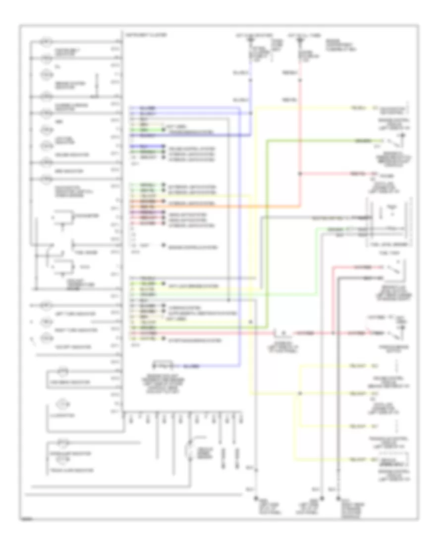
INSTRUMENT CLUSTER
Instrument Cluster Wiring Diagram, GL Model for Hyundai Elantra 1996
 https://portal-diagnostov.com/license.html
Automotive Electricians Portal FZCO
Automotive Electricians Portal FZCO
https://portal-diagnostov.com/license.html
https://portal-diagnostov.com/license.html
Automotive Electricians Portal FZCO
Automotive Electricians Portal FZCO
List of elements for Instrument Cluster Wiring Diagram, GL Model for Hyundai Elantra 1996:
- "brake" system indicator
- "o/d off" indicator
- (not used)
- Abs
- Anti-lock brakes system
- Brake fluid level switch (left rear corner of engine compt)
- Burg alarm b+ 10a
- C11
- Charge warning indicator
- Coolant temperature gauge
- Cruise control module (behind center of i/p)
- Cruise control system
- Cruise indicator
- Dash fuse box
- Data link connector (left side of i/p)
- Diode z01 (left side of i/p, at kick panel)
- Door ajar indicator
- Engine compartment fuse/relay box
- Engine control module (left side of i/p)
- Engine coolant temperature sender (left side of intake manifold, near coolant outlet)
- Engine oil pressure switch (beside exhaust manifold)
- Etacs, cluster fuse 10 10a
- Exterior lights system
- Fasten belt indicator
- Fuel gauge
- Fuel level sender
- Fuel tank
- G131 (right rear of engine, on intake manifold)
- G200 (left side of i/p, at kick panel)
- Headlights system
- High beam indicator
- Hot at all times
- Hot in on or start
- I03
- I04-1
- I04-2
- I04-3
- Illumination
- Instrument cluster
- Interior lights system
- Left turn indicator
- Low fuel indicator
- Malfunction ind control
- Malfunction indicator lamp (mil) (check engine)
- Nca
- Oil
- Parking brake switch
- Power
- Right turn indicator
- Srs indicator
- Starting/charging system
- Tachometer
- Transaxle control module (left side of i/p)
- Transmissions system
- Trunk ajar indicator
- Vehicle speed input
- Vehicle speed sensor
- Warning system
Instrument Cluster Wiring Diagram, GLS Model for Hyundai Elantra 1996
List of elements for Instrument Cluster Wiring Diagram, GLS Model for Hyundai Elantra 1996:
- "brake" system indicator
- "o/d off" indicator
- (not used)
- Abs
- Anti-lock brakes system
- Brake fluid level switch (left rear corner of engine compt)
- Burg alarm b+ 10a
- C11
- Charge warning indicator
- Coolant temperature gauge
- Cruise control module (behind center of i/p)
- Cruise control system
- Cruise indicator
- Dash fuse box
- Data link connector (left side of i/p)
- Diode z01 (left side of i/p, at kick panel)
- Door ajar indicator
- Engine compartment fuse/relay box
- Engine control module (left side of i/p)
- Engine controls system
- Engine coolant temperature sender (left side of intake manifold, near coolant outlet)
- Engine oil pressure switch (beside exhaust manifold)
- Etacs, cluster fuse 10 10a
- Exterior lights system
- Fasten belt indicator
- Fuel gauge
- Fuel level sender
- Fuel tank
- G131 (right rear of engine, on intake manifold)
- G200 (left side of i/p, at kick panel)
- Headlights system
- High beam indicator
- Hot at all times
- Hot in on or start
- I01-1
- I01-2
- I01-3
- I03
- Illumination
- Instrument cluster
- Interior lights system
- Left turn indicator
- Low fuel indicator
- Malfunction ind control
- Malfunction indicator lamp (mil) (check engine)
- Nca
- Oil
- Parking brake switch
- Power
- Right turn indicator
- Srs indicator
- Starting/charging system
- Tachometer
- Transaxle control module (left side of i/p)
- Transmissions system
- Trunk ajar indicator
- Vehicle speed input
- Vehicle speed sensor
- Warning system

 Čeština
 Dansk
Dansk Deutsch
 English
 English
 Español
 Suomi
Suomi Français
 Français
 עברית
עברית Hrvatski
 Magyar
 Italiano
 日本語
日本語 한국어
한국어 Nederlands
 Polski
 Português
 Português
 Română
 Русский
 Slovenčina
 Slovenščina
 Svenska
 Türkçe
 中文 (中国)