ELECTRONIC SUSPENSION
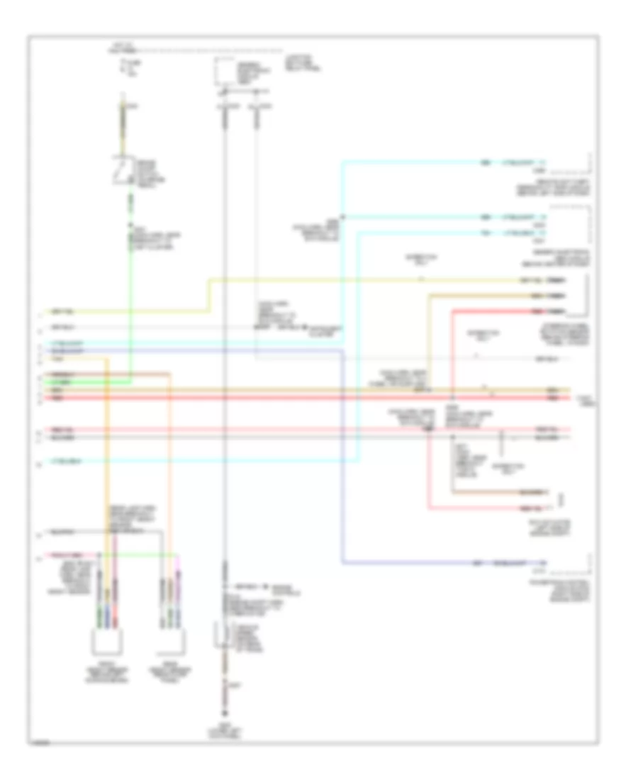
Electronic Suspension Wiring Diagram (1 of 2) for Ford Expedition 1998

List of elements for Electronic Suspension Wiring Diagram (1 of 2) for Ford Expedition 1998:
- (main harn, near breakout to 4was module) s272
- 4x4 low sig
- Air suspension compressor motor and vent solenoid (right radiator support)
- Air suspension compressor relay (near right headlamp)
- Air suspension indicator
- Air suspension service switch (behind right side of dash)
- Air suspension/ evo steering module (behind center of dash)
- All wheel drv
- Brake on/off sw
- C237
- C242
- C243
- C295
- C296
- Comp mtr vent sol
- Compressor relay
- Data link connector (under center of dash)
- Datalink
- Door ajar in
- Evo module
- Front air fill solenoid
- Front fill sol
- Front gate sol
- Front gate solenoid
- Front height sen
- Fuse 15a
- Fuse 50a
- Fuse 5a
- G108 (left front radiator suport)
- G109 (right front radiator suport)
- G109 (right front radiator support)
- G200 (lower left kick panel)
- G203 (lower right kick panel)
- Ground
- Height sen power
- Hot at all times
- Hot in run
- Hot in start
- Instrument cluster
- Junction box fuse/ relay panel
- Left rear air spring solenoid
- Lr spring sol
- Memory systems
- Pcm accel sig
- Pnk
- Power (hot in run)
- Power (start)
- Power distribution box
- Rear air fill solenoid
- Rear fill sol
- Rear height sen
- Red
- Right rear air spring solenoid
- Rr spring sol
- S104
- S155
- S177
- S210
- S229 (main harn, near breakout to evo module)
- S265
- S400
- Service switch
- Solid state
- Steering sensor
- Tan
- Transmission controls
- Vehicl speed (+)
- Warning indicator
Electronic Suspension Wiring Diagram (2 of 2) for Ford Expedition 1998
List of elements for Electronic Suspension Wiring Diagram (2 of 2) for Ford Expedition 1998:
- (main harn, near breakout to 4 wheel air susp mod) s270
- (main harn, near breakout to evo module) s267
- (main harn, near breakout to evo module) s273
- (not used)
- (rear lamp harn, near breakout to front height sensor)
- (rear lamp harn, near breakout to front height sensor) s410 or s310
- Brake on/off switch (on brake pedal)
- Breakout to inst cluster)
- C174
- C240
- C241
- C256
- Engine controls
- Evo actuator (left side of engine compt)
- Expedition only
- Front height sensor (behind left running board)
- Fuse 15a
- G200 (lower left kick panel)
- Generic electronic (gem) module (behind center of dash)
- Generic electronic module (gem)
- Hot at all times
- Instrument cluster
- Junction box fuse/ relay panel
- Nca
- Powertrain control module (pcm) (right side of engine compt)
- Rear height sensor (rear floor panel)
- Red
- Remote anti-theft personality (rap) module (behind left side of dash)
- S207
- S268 (main harn, near breakout to evo module)
- S269 (main harn, near breakout to evo module)
- S271 (main harn, near breakout to evo module)
- S409 or s311
- Steering wheel rotation sensor (behind steering wheel, in dash)
- Tan
- Vehicle speed sensor (on rear of trans)