SUPPLEMENTAL RESTRAINTS
Supplemental Restraint Wiring Diagram for Ford Expedition 1998
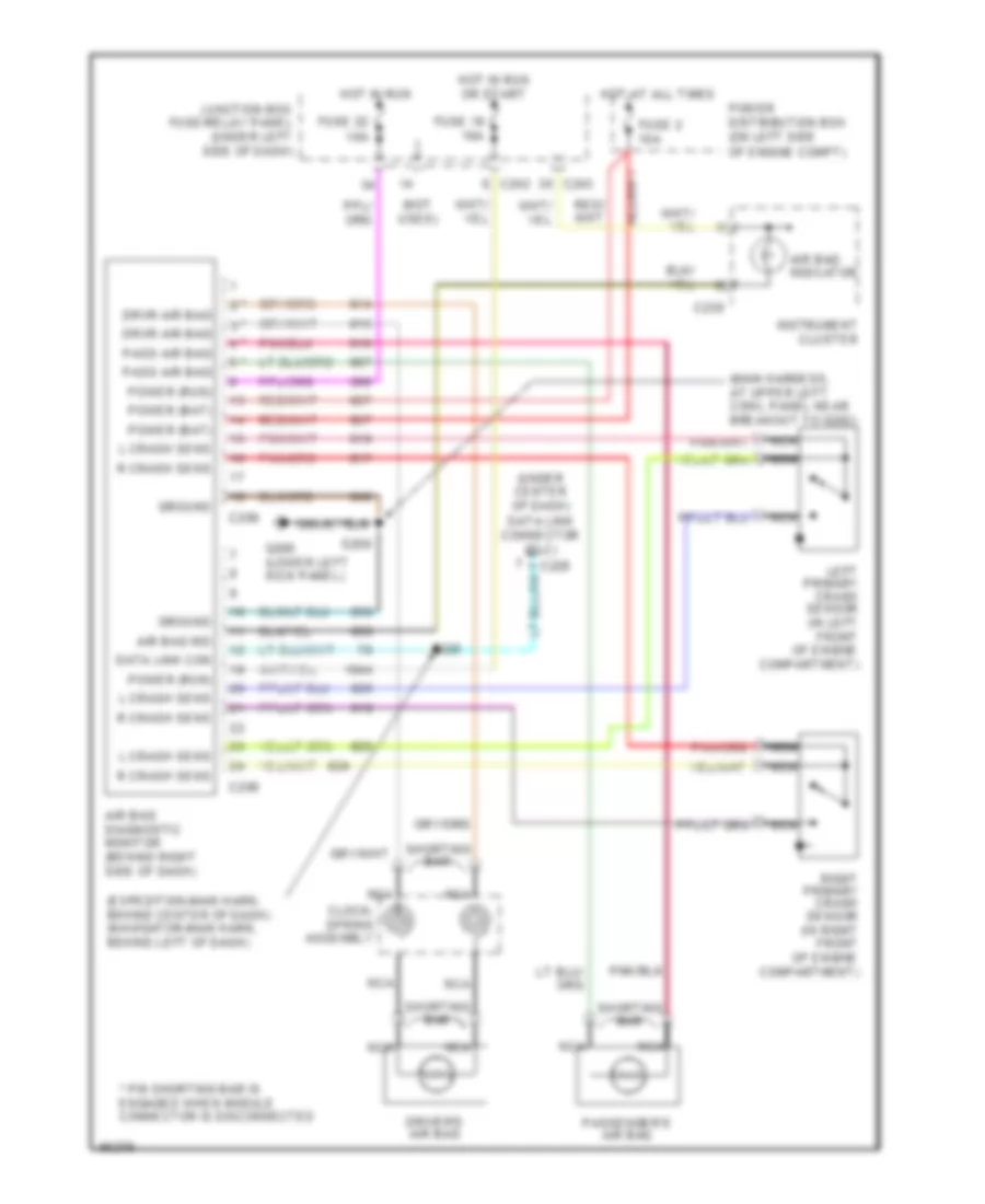
List of elements for Supplemental Restraint Wiring Diagram for Ford Expedition 1998:
- (expedition-main harn, behind center of dash) (navigator-main harn, behind left of dash)
- (main harness, at upper left cowl panel near breakout to g202)
- (not used)
- (under center of dash) data link connector (dlc)
- * pin shorting bar is engaged when module connector is disconnected
- Air bag diagnostic monitor (behind right side of dash)
- Air bag ind
- Air bag indicator
- C208
- C209
- C228
- C238
- C242
- C243
- Clock- spring assembly
- Data link con
- Driver's air bag
- Drvr air bag
- Fuse 19 10a
- Fuse 2 10a
- Fuse 22 10a
- G200 (lower left kick panel)
- Ground
- Hot at all times
- Hot in run
- Hot in run or start
- Instrument cluster
- Junction box fuse/relay panel (under left side of dash)
- L crash sens
- Left primary crash sensor (in left front of engine compartment)
- Nca
- Pass air bag
- Passenger's air bag
- Power (bat)
- Power (run)
- Power distribution box (on left side of engine compt)
- R crash sens
- Right primary crash sensor (in right front of engine compartment)
- S208
- S229
- Shorting bar
 English