SHIFT INTERLOCKS
Shift Interlock Wiring Diagram, Early Production for Isuzu Rodeo S 1995
 https://portal-diagnostov.com/license.html
Automotive Electricians Portal FZCO
Automotive Electricians Portal FZCO
https://portal-diagnostov.com/license.html
https://portal-diagnostov.com/license.html
Automotive Electricians Portal FZCO
Automotive Electricians Portal FZCO
List of elements for Shift Interlock Wiring Diagram, Early Production for Isuzu Rodeo S 1995:
- (below shift lever cover)
- (not used)
- Battery
- Brake input
- Brake light switch (on brake pedal support)
- C264
- C270
- Charge sig
- Dash fuse box (left side of i/p)
- Fuse 10a
- Fuse/ relay box (right side of engine compartment)
- G200 (left side kick panel)
- Ground
- Hot at all times
- Hot in on or start
- Ignition
- Park input
- Parking switch (below shift lever cover)
- Red
- Ref signal
- Safety lock control unit (below shift lever cover)
- Shift lock solenoid
- Solenoid control
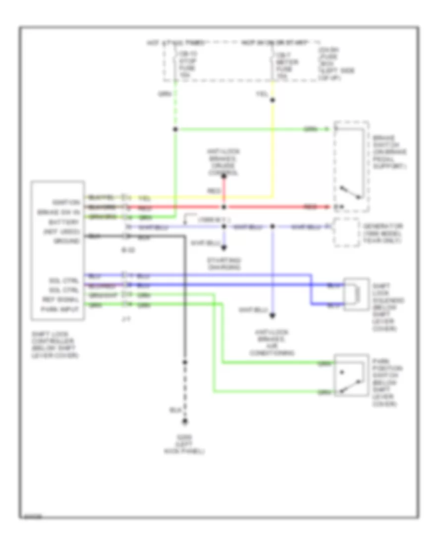
Shift Interlock Wiring Diagram, Late Production for Isuzu Rodeo S 1995
List of elements for Shift Interlock Wiring Diagram, Late Production for Isuzu Rodeo S 1995:
- (1996 m.y.)
- (not used)
- Anti-lock brakes, air conditioning
- Anti-lock brakes, cruise control
- B-32
- Battery
- Brake sw in
- Brake switch (on brake pedal support)
- Cb-13 stop fuse 15a
- Cb-7 meter fuse 15a
- Dash fuse box (left side of i/p)
- G200 (left kick panel)
- Generator (1996 model year only)
- Ground
- Hot at all times
- Hot in on or start
- Ignition
- J-1
- Park input
- Park position switch (below shift lever cover)
- Red
- Ref signal
- Shift lock controller (below shift lever cover)
- Shift lock solenoid (below shift lever cover)
- Sol ctrl
- Starting/ charging

 Čeština
 Dansk
Dansk Deutsch
 Ελληνικά
 English
 Español
 Suomi
Suomi Français
 Français
 עברית
עברית Hrvatski
 Magyar
 Italiano
 日本語
日本語 한국어
한국어 Nederlands
 Polski
 Português
 Português
 Română
 Русский
 Slovenčina
 Slovenščina
 Svenska
 Türkçe
 中文 (中国)