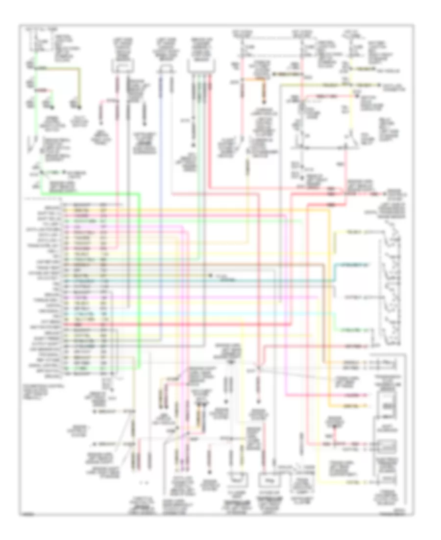
TRANSMISSION
A/T Wiring Diagram for Ford Crown Victoria 2001
List of elements for A/T Wiring Diagram for Ford Crown Victoria 2001:
- (behind air cleaner assembly) mass air- flow (maf) sensor
- (dash harn, near breakout to data link connector)
- (engine compt harn, lower left of engine)
- (engine compt harn, near front crash sensor)
- (engine compt harn, right rear of engine)
- (engine harn, left rear corner of engine compt)
- (engine harn, left rear of engine compt)
- (engine harn, left rear of engine compt) s129
- (left side of trans- mission)
- (left side of trans- mission) output shaft speed (oss) sensor
- (left side of transmission) digital transmission range sensor
- (rear of left front fender apron)
- (rear of left front fender g101 apron)
- (trans harn, left rear of engine compartment)
- (trans harn, left rear of trans)
- 4r70w transmission
- A/c cutout
- Abs module,
- Analog
- Anti-theft system,
- Battery junction box (right front of engine compt)
- Bpp switch
- Brake pedal position (bpp) switch (top of brake pedal support)
- C220b
- Central junction box (below dash, left of steering column)
- Cht sens
- Cylinder head
- Data link +
- Data link -
- Data link connector
- Data link connector (partial) (behind left side of dash)
- Data link power
- Digital
- Eatc module
- Elect press
- Electronic pressure control solenoid
- Engine controls system
- Exterior lights
- Floor shifter (5 pass- enger vehicle)
- Fuse 15a
- Fuse 25a
- Fuse 30a
- G101
- G101 (rear of left front fender apron)
- G201 (behind
- Ground
- Hot at all times
- Hot in run or start
- Ignition coils, radio noise capacitor
- Ignition power
- Instrument cluster
- Instrument cluster, cruise control, electronic suspension
- Intake air
- Intake air temp
- Kapwr
- Lighting control module, instrument cluster
- Maf return
- Maf sensor sig
- Multi- function switch
- Ngv module
- Output shaft
- Overdrive cancel switch (6 passenger vehicle)
- Passive anti-theft system control module
- Pcm power diode
- Pcm power relay
- Powertrain control module (pcm) (left side of firewall)
- R p
- Red
- Red red
- Ref votage
- Relay center box 1 (left side of engine compt)
- Right kick panel)
- S100
- S105
- S115
- S119
- S123
- S125
- S126
- S132
- S134
- S135
- S147
- S148
- S155
- S223
- S263
- S265
- S276
- S296
- S297
- Shift sol a
- Shift sol b
- Shift solenoids
- Signal control
- Speed control deactivator switch
- Ss a
- Ss b
- System
- Tci lamp
- Temperature (cht) sensor (top left front of engine)
- Temperature (iat) sensor (left front of engine) compt)
- Throttle position (tp) sensor (left side of throtle body)
- To a/c
- Torque conv
- Torque converter clutch (tcc) solenoid
- Tps signal
- Tr1
- Tr2
- Tr3
- Tr4
- Trans cntrl sw
- Trans control indicator lamp
- Trans temp
- Transmission fluid temperature sensor
- Vehicle speed sensor
- Vss (-)
- Vss signal
- Warning lamps module,
 Čeština
 Dansk
Dansk Deutsch
 Ελληνικά
 English
 Español
 Suomi
Suomi Français
 Français
 עברית
עברית Hrvatski
 Magyar
 Italiano
 日本語
日本語 한국어
한국어 Nederlands
 Polski
 Português
 Português
 Română
 Русский
 Slovenčina
 Slovenščina
 Svenska
 Türkçe
 中文 (中国)
 English