TRANSMISSION
3.0L
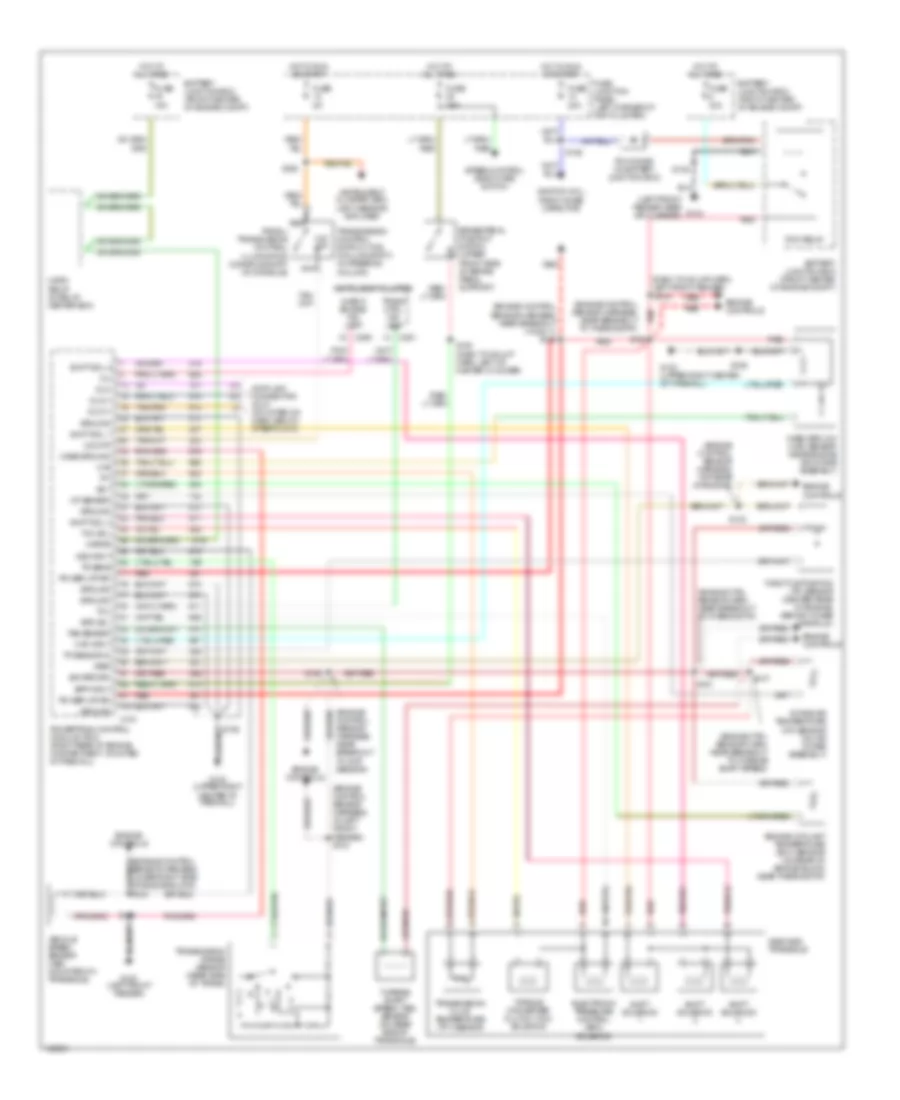
3.0L 12-Valve, A/T Wiring Diagram for Mercury Sable GS 1999
 https://portal-diagnostov.com/license.html
Automotive Electricians Portal FZCO
Automotive Electricians Portal FZCO
https://portal-diagnostov.com/license.html
https://portal-diagnostov.com/license.html
Automotive Electricians Portal FZCO
Automotive Electricians Portal FZCO
List of elements for 3.0L 12-Valve, A/T Wiring Diagram for Mercury Sable GS 1999:
- (dash panel to headlamp harn, left front fender)
- (dash panel to junction wiring assembly, near left front fender) s133
- (engine control sensor harness, lower right side of engine block) s104
- (engine control sensor harness, near breakout to ckp sensor) s107
- (engine control sensor harness, near breakout to inj 6) s110
- (engine control sensor harness, near breakout to near fuel inj 5)
- (engine control sensor harness, top rear of engine)
- (engine control sensor harness, top rear of engine) s103
- (engine control sensor harness, upper rear side of trans)
- Ax4s/ax4n transaxle
- Battery junction box (front center of engine compt)
- Bpp input
- Brake pedal position switch (upper front side of brake pedal support)
- C191
- Case ground
- Check engine ind lamp c250
- Data link connector (dlc) (mounted on dash, below steering column)
- Digital transmission range sensor
- Dlc
- Dlc(+)
- Dlc(-)
- Ect
- Electronic pressure control (epc) solenoid
- Engine controls
- Engine coolant temperature (ect) sensor (on rear of engine block near thermostat)
- Epc sol
- Fuse 15a
- Fuse 20a
- Fuse 30a
- Fuse junction panel (left corner of inst cluster)
- G100 (left front fender)
- G104 (left front fender near air cleaner)
- G123 (upper right center of firewall)
- Ground
- Horn relay (in relay center box)
- Hot at all times
- Hot in run or start
- Iat sensor
- Ignition coil, radio noise capacitor
- Instrument cluster
- Intake air temperature (iat) sensor (on air intake assembly)
- Kapwr
- Maf
- Maf input
- Mass airflow (maf) sensor (near engine air intake assembly)
- Mil
- Pcm diode (in battery junction box)
- Pcm relay
- Power (vpwr)
- Powertrain control module (pcm) (right rear of engine compartment, mounted in firewall)
- Red
- S101
- S102
- S105
- S106
- S111
- S134
- S135
- S138 (dash to hdlmp harn, left of master cylinder)
- Shift sol 1
- Shift sol 2
- Shift sol 3
- Shift solenoid
- Sig return
- Speed control deactivate switch
- Tcc sol
- Tft
- Throttle position (tp) sensor (top right side of engine, behind intake manifold)
- Torque converter clutch (tcc) solenoid
- Tp sensor in
- Tr1
- Tr2
- Tr3
- Tr4
- Transmission fluid temperature (tft) sensor
- Tss sensor
- Turbine shaft speed (tss) sensor (on rear side of transaxle)
- Vehicle speed sensor (vss) (mounted on trans- axle)
- Vref
- Vss input
3.0L 24-Valve, A/T Wiring Diagram for Mercury Sable GS 1999
List of elements for 3.0L 24-Valve, A/T Wiring Diagram for Mercury Sable GS 1999:
- (dash to hdlmp harn, left front fender)
- (engine control sensor harness, at left front fender) s134
- (engine control sensor harness, lower right side of engine block) s104
- (engine control sensor harness, near breakout ho2s 11) s152
- (engine control sensor harness, near breakout to cmp sensor)
- (engine control sensor harness, near breakout to thermostat)
- (engine control sensor harness, top rear of engine)
- (engine ctrl sensor harn, near breakout to thermostat)
- (engine ctrl sensor harn, near breakout to turbine shaft speed)
- (left front fender near air cleaner)
- Ax4s/ax4n transaxle
- Battery junction box (front center of engine compt)
- Bpp input
- Brake pedal position switch (upper front side of brake pedal support)
- C191
- C250
- C251
- Case ground
- Check engine ind lamp
- Data link connector (dlc) (mounted on dash, below steer clmn)
- Dlc
- Dlc(+)
- Dlc(-)
- Ect
- Electronic pressure control (epc) solenoid
- Engine controls
- Engine coolant temperature (ect) sensor (on rear of engine block near thermostat)
- Epc sol
- Fuse 15a
- Fuse 20a
- Fuse 30a
- Fuse 5a
- Fuse junction panel (left corner of inst cluster)
- G100 (left front fender)
- G104
- G123 (upper right center of firewall)
- Ground
- Horn relay (in relay center box)
- Hot at all times
- Hot in run or start
- Iat sensor
- Ignition coil, radio noise capacitor
- Instrument cluster
- Instrument cluster, gem, light sensor/ amplifier
- Intake air temperature (iat) sensor (on air intake assembly)
- Kapwr
- Maf
- Maf input
- Mass airflow (maf) sensor (near engine air intake assembly)
- Mil
- N d
- Nca
- O/d off
- Pcm diode (in battery junction box)
- Pcm relay
- Power (vpwr)
- Powertrain control module (pcm) (right rear of engine compartment, mounted in firewall)
- Prndl/ transmission control illumination (console shift) (in console)
- Red
- S102
- S105
- S106
- S122
- S133
- S135
- S138 (dash to hdlmp harn, left of master cylinder)
- S147
- S150
- S151
- S153
- S224
- Shift sol 1
- Shift sol 2
- Shift sol 3
- Shift solenoid
- Sig return
- Speed control deactivate switch
- Tcc sol
- Tcil
- Tft
- Throttle position (tp) sensor (center rear of engine, behind intake manifold)
- Torque converter clutch (tcc) solenoid
- Tp sensor in
- Tr sens
- Trans ctrl ind lamp
- Transmission control switch (tcs) (column shift) (in steering column)
- Transmission fluid temperature (tft) sensor
- Transmission range sensor (rear side of trans)
- Tss sensor
- Turbine shaft speed (tss) sensor (on rear side of transaxle)
- Vehicle speed sensor (vss) (mounted on transaxle)
- Vref
- Vss input

 Čeština
 Dansk
Dansk Deutsch
 Ελληνικά
 English
 Español
 Suomi
Suomi Français
 Français
 עברית
עברית Hrvatski
 Magyar
 Italiano
 日本語
日本語 한국어
한국어 Nederlands
 Polski
 Português
 Português
 Română
 Русский
 Slovenčina
 Slovenščina
 Svenska
 Türkçe
 中文 (中国)