ANTI-LOCK BRAKES
Anti-lock Brake Wiring Diagrams (1 of 2) for Isuzu Trooper LS 1997

List of elements for Anti-lock Brake Wiring Diagrams (1 of 2) for Isuzu Trooper LS 1997:
- (below left front seat)
- (braided wire)
- 4wd ind
- 4wd sw in
- Abs g-sensor (rear of park brake lever)
- Abs ind
- Abs ind ctrl
- Brake in
- Brake switch (w/ cruise control)
- Dash fuse box (left i/p)
- Data link connector (partial) (left side of dash)
- Dlc in/out
- Elec ign fuse c-4 10a
- Electronic brake control module (83-pin conn: unused pins 55-82 not shown) (below right front seat)
- Fl whl spd lo
- Front axle switch (center of front axle)
- G-sensor
- G104 (rear of left front fender)
- G206 (right of center console)
- G300
- G302 (below center console)
- Gnd
- Hot at all times
- Hot in on or start
- I-10
- I-9
- Ign in
- Instrument cluster
- Left front abs speed sensor (inside of left front wheel)
- Left rear abs speed sensor (inside of left rear wheel)
- Lf av ctrl
- Lf ev ctrl
- Lf whl spd hi
- Lr whl spd hi
- Lr whl spd lo
- Meter gauge fuse c-10 10a
- Motor rly ctrl
- Nca
- Nca c-85
- Pump motor on
- R av ctrl
- R ev ctrl
- Red
- Rev/low gear in
- Rf av ctrl
- Rf ev ctrl
- Rf whl spd hi
- Rf whl spd lo
- Right front abs speed sensor (inside of right front wheel)
- Right rear abs speed sensor (inside of right rear wheel)
- Rr whl spd hi
- Rr whl spd lo
- Stop a/t cont fuse c-14 15a
- Stop light switch (w/o cruise control)
- Valve motor rly
- Valve rly ctrl
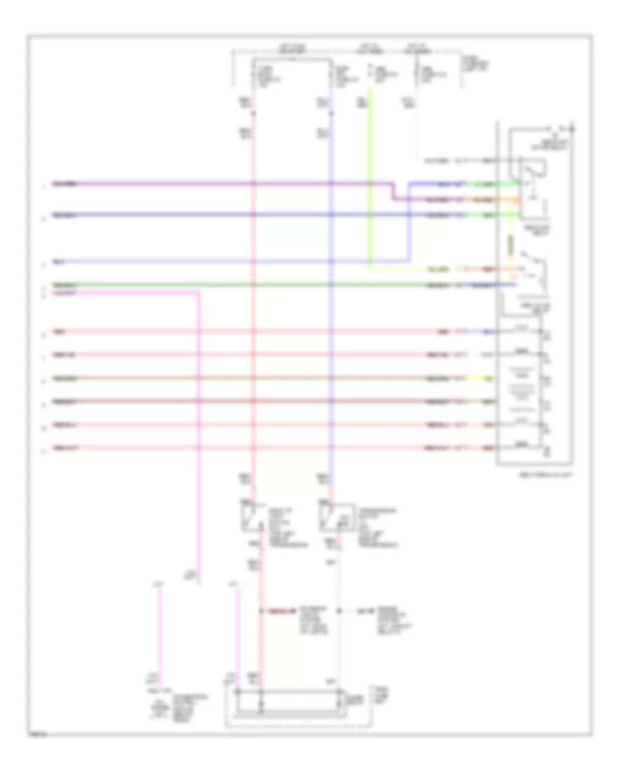
Anti-lock Brake Wiring Diagrams (2 of 2) for Isuzu Trooper LS 1997
List of elements for Anti-lock Brake Wiring Diagrams (2 of 2) for Isuzu Trooper LS 1997:
- 1st/ 2nd
- A/t
- A12
- Abs fuse f-9 20a
- Abs fuse fl-6 40a
- Abs hydraulic unit
- Abs pump motor relay
- Abs pump relay
- Abs valve relay
- Back up light switch (m/t) (top left side of transmission)
- C-1
- Dash fuse box
- Dash fuse box (left i/p)
- Diode box 6
- Elec ign fuse c-4 10a
- Engine controls system (m/t: upshift relay-2)
- Exterior lights system (m/t: back up lights)
- Hot at all times
- Hot in on or start
- Lf av
- Lf ev
- M/t
- Powertrain control module (below radio)
- R av
- R ev
- R/l range out
- Red
- Rf av
- Rf ev
- Transmission switch 1-2 (m/t) (top left side of transmission)
- Turn back fuse c-3 15a