
SUPPLEMENTAL RESTRAINTS
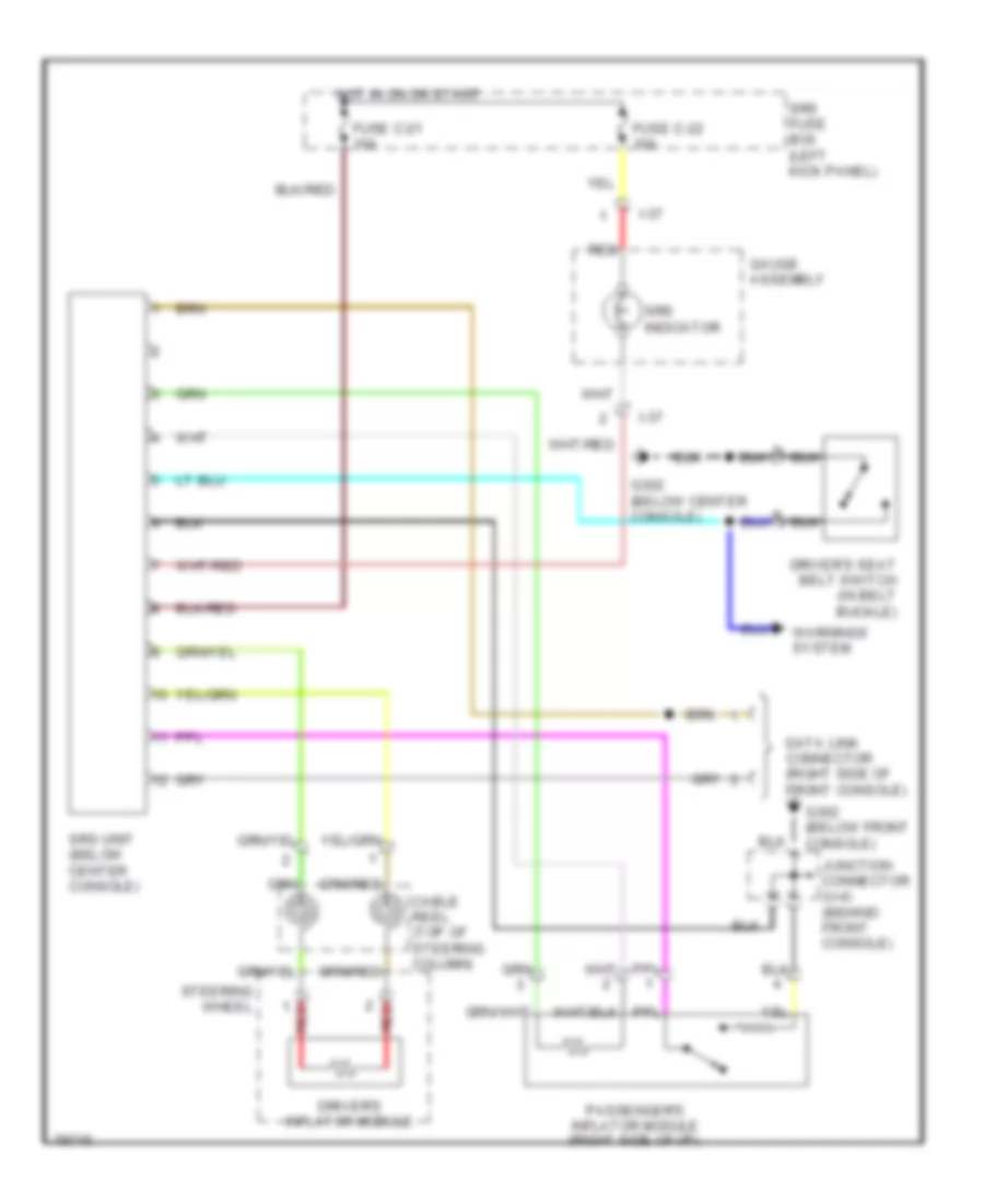
Supplemental Restraint Wiring Diagram for Isuzu Trooper LS 1997
List of elements for Supplemental Restraint Wiring Diagram for Isuzu Trooper LS 1997:
AIR CONDITIONINGANTI-LOCK BRAKESENGINE PERFORMANCECOMPUTER DATA LINESANTI-THEFTCRUISE CONTROLEXTERIOR LIGHTSGROUND DISTRIBUTIONDEFOGGERSHEADLIGHTSHORNINTERIOR LIGHTSPOWER DOOR LOCKSINSTRUMENT CLUSTERPOWER DISTRIBUTIONPOWER MIRRORSPOWER WINDOWSPOWER SEATSPOWER TOP/SUNROOFSHIFT INTERLOCKSRADIOSTARTING/CHARGINGSUPPLEMENTAL RESTRAINTSWARNING SYSTEMSTRANSMISSIONWIPER/WASHER