ENGINE PERFORMANCE
3.7L
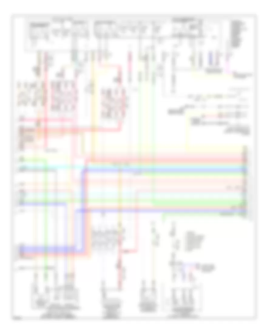
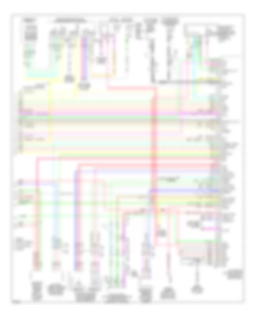
3.7L, Engine Performance Wiring Diagram (1 of 6) for Infiniti G37 x 2013

List of elements for 3.7L, Engine Performance Wiring Diagram (1 of 6) for Infiniti G37 x 2013:
- (1, 3 & 5: top of cylinder bank 1) (2, 4 & 6: top of cylinder bank 2)
- 2wd
- Abort
- Af+1
- Af-1
- Afh1
- Afh2
- Avcc-phase 1
- Avcc-phase 2
- Avcc-pos
- Avcc-tps-b1
- Avcc-tps-b2
- Avcc2/mvpres
- Brake booster pressure sensor (on brake fluid reservoir)
- Close
- Computer data lines system
- Condenser (body) (in left "c" pillar)
- Convertible
- Coupe awd
- Crankshaft position sensor (pos) (right rear of engine)
- Cvt 2
- Cvtc 1
- Ecm (engine control module) (under right end of dash)
- Electric throttle control actuator (bank 2) (on throttle body assembly)
- Eng can-h1
- Eng can-l1
- Evap
- Except sedan
- F1 e3
- F101
- F102
- F104
- F105
- F106
- F107
- F109
- F110
- F110 f109
- F34 (right front of engine)
- F39 e40
- Fpr
- Gnd
- Gnd-pos
- Gnda-tps-b1
- Gnda-tps-b2
- Gnda/intpres/mvpres
- Ign 1
- Ign 2
- Ign 3
- Ign 4
- Ign 5
- Ign 6
- Ignition coil 1 (w/ power transistor)
- Ignition coil 2 (w/ power transistor)
- Ignition coil 3 (w/ power transistor)
- Ignition coil 4 (w/ power transistor)
- Ignition coil 5 (w/ power transistor)
- Ignition coil 6 (w/ power transistor)
- Ignsw
- Intake valve timing control solenoid valve (bank 1) (front of cylinder bank 1)
- Intake valve timing control solenoid valve (bank 2) (front of cylinder bank 2)
- Intpres 1
- M95 (behind right side of dash)
- Motarly1
- Motor1-b1
- Motor1-b2
- Motor2-b1
- Motor2-b2
- Mvrees
- Nca
- O2hr1
- O2hr2
- Open
- Phase 1
- Phase 2
- Pnk
- Pos
- Red
- Sedan
- Sedan awd
- Sensor 1
- Sensor 2
- Spark plug
- Ssoff
- Tan
- Throttle control motor
- Throttle position sensor
- Tps 2-b1
- Tps 2-b2
- Tps1-b1
- Tps1-b2
- Vmot-b2
- Vmot1-b1
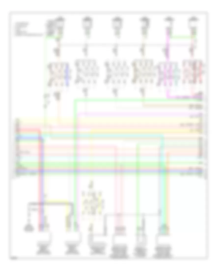
3.7L, Engine Performance Wiring Diagram (2 of 6) for Infiniti G37 x 2013
List of elements for 3.7L, Engine Performance Wiring Diagram (2 of 6) for Infiniti G37 x 2013:
- (or red)
- -h can
- -l can
- 2wd
- A/t
- A/t assembly (at rear of engine compt)
- Close
- Computer data lines system
- Convertible
- Cooling fans system
- Coupe awd
- Cpu
- E106
- E22
- E40
- Ecm relay
- Electric throttle control actuator (bank 1) (on throttle body assembly)
- Evap canister purge volume control solenoid valve (rear of engine compt)
- Except sedan
- F103
- F104
- F105
- F106
- F107
- F107 f106
- F109
- F110
- F39
- F51
- Fuel pump relay
- Fuse 10a
- Fuse 15a
- Hot at all times
- Hot in on or start
- Ignition relay
- Ill
- Ind
- Interior lights system
- Ipdm e/r intelligent power distribution module (engine room) (at right rear of engine compt)
- J/c
- M/t
- M116
- M116 f103
- M6 e106
- M95 (behind right side of dash)
- Nca
- Open
- Park/neutral position switch (at rear of transmission)
- Pnk
- Red
- Red (or
- Red (or pnk)
- Rly str
- Sedan
- Sedan awd
- Sensor 1
- Sensor 2
- Snow mode switch (except convertible & awd)
- Tan
- Tcm (transmission control module)
- Throttle control motor
- Throttle control motor relay
- Throttle position sensor
3.7L, Engine Performance Wiring Diagram (3 of 6) for Infiniti G37 x 2013
List of elements for 3.7L, Engine Performance Wiring Diagram (3 of 6) for Infiniti G37 x 2013:
- (1, 3 & 5: top of cylinder bank 1) (2, 4 & 6: top of cylinder bank 2)
- (or red)
- (or tan)
- Air fuel ratio sensor 1 (bank 1) (under right side of engine)
- Air fuel ratio sensor 1 (bank 2) (under left side of engine)
- Awd
- Convertible
- Coupe 2wd
- Engine coolant temperature sensor (rear of engine)
- Engine oil temperature sensor (bottom front of engine)
- Except convertible & awd
- F10
- F104
- F105
- F105 f104
- F106
- F107
- F109
- F109 f110
- F110
- F120
- Fuel injector 1
- Fuel injector 2
- Fuel injector 3
- Fuel injector 4
- Fuel injector 5
- Fuel injector 6
- Heated oxygen sensor 2 (bank 1) (on right side exhaust pipe, between three-way catalysts 1 & 2)
- Heated oxygen sensor 2 (bank 2) (on left side exhaust pipe, between three-way catalysts 1 & 2)
- M95 (behind right side of dash)
- Nca
- Pnk
- Red
- Sedan 2wd
- Tan
- Tan) (or
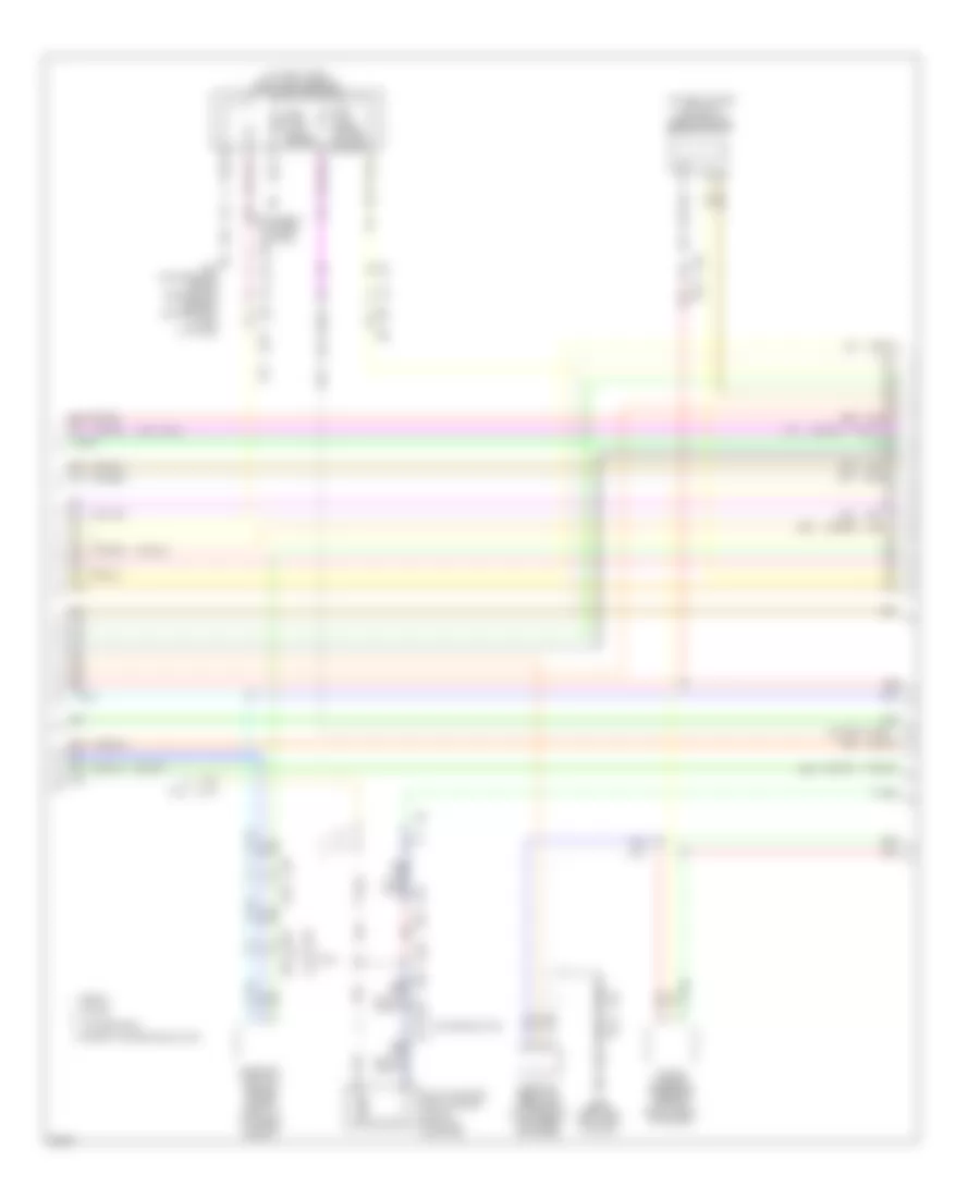
3.7L, Engine Performance Wiring Diagram (4 of 6) for Infiniti G37 x 2013
List of elements for 3.7L, Engine Performance Wiring Diagram (4 of 6) for Infiniti G37 x 2013:
- (at fuel tank) fuel level sensor unit & fuel pump (main)
- (on left intake air duct) mass airflow sensor (bank2)
- (or red)
- (or tan)
- 2wd
- B24 (convertible: behind rear seats) (except convertible: in left "c" pillar)
- B332 b254
- B39 b331
- B70
- B71
- B75
- Camshaft position sensor (phase) (bank 2) (front of cylinder bank 2)
- Convertible
- Coupe
- E117
- E118
- E79
- Evap canister vent control valve (on evap canister)
- Except convertible & awd
- F103
- F103 m116
- F106
- F107
- F109
- F110
- Fuel tank level sensor
- Fuel tank tempe- rature sensor
- Instrument cluster system
- Late production
- M116
- M95 (behind right side of dash)
- Manifold absolute pressure (map) sensor (left rear of engine)
- Pnk
- Power steering pressure sensor (right front of engine)
- Red
- Sedan
- Tan
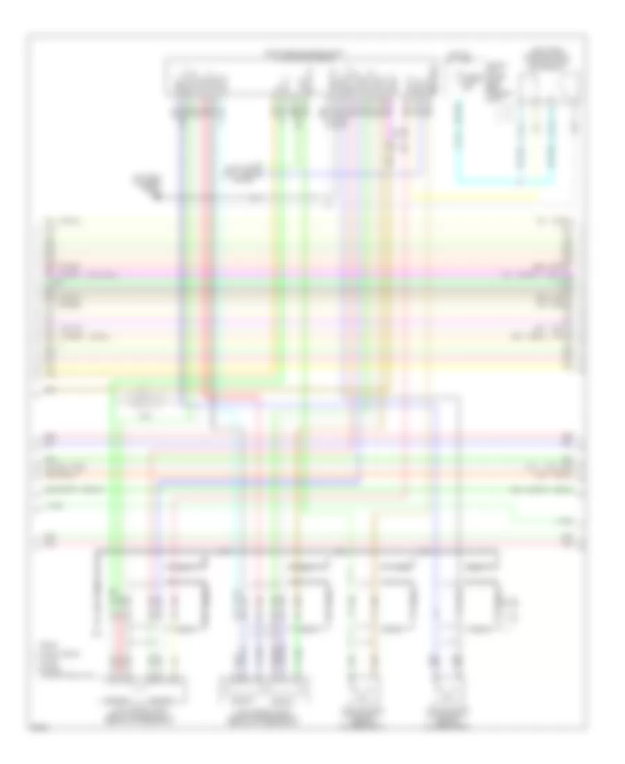
3.7L, Engine Performance Wiring Diagram (5 of 6) for Infiniti G37 x 2013
List of elements for 3.7L, Engine Performance Wiring Diagram (5 of 6) for Infiniti G37 x 2013:
- (left rear of engine compt) e46
- (or red)
- (or tan)
- (right rear of engine compt) vvel actuator motor relay
- (right rear of engine compt) vvel control module
- Abort
- Agnd1
- Agnd2
- Agnd3
- Agnd4
- Avcc1
- Avcc2
- Avcc3
- Avcc4
- Awd
- Can h
- Can l
- Computer data lines system
- Coupe
- E22
- E40
- Except convertible & awd
- Except sedan
- F106
- F107
- F109
- F110
- F39
- Fusible link holder (right rear of engine compt)
- Fusible link n 50a
- Hot at all times
- M-rly
- Motor l 1
- Motor l 2
- Motor r1
- Motor r2
- Nca
- Pgnd l
- Pnk
- Red
- Sedan
- Sensor 1
- Sensor 2
- Shield
- Tan
- V-mot (r)
- Vel s-r2
- Vel/s-l1
- Vel/s-r1
- Vmot l
- Vvel actuator motor (bank 1) (rear of cylinder bank 1)
- Vvel actuator motor (bank 2) (rear of cylinder bank 2)
- Vvel control shaft position sensor (bank 1) (rear of cylinder bank 1)
- Vvel control shaft position sensor (bank 2) (rear of cylinder bank 2)
3.7L, Engine Performance Wiring Diagram (6 of 6) for Infiniti G37 x 2013
List of elements for 3.7L, Engine Performance Wiring Diagram (6 of 6) for Infiniti G37 x 2013:
- (behind center of dash) unified meter & a/c amplifier
- (or red)
- (or tan)
- (top center of cylinder bank 1) knock sensor (bank 1)
- (top center of cylinder bank 2) knock sensor (bank 2)
- Accelerator pedal position sensor (on accelerator pedal bracket)
- Af+2
- Af-2
- Amp
- Amp lcd
- Aps1
- Aps2
- Ascdsw
- Avcc-aps1
- Avcc-aps2
- Avcc-ftprs
- B332 b254
- B39 b331
- B70
- B71
- Bat
- Batt
- Battery current sensor (right rear of engine compt, at battery)
- Bncsw
- Brake
- Camshaft position sensor (phase) (bank 1) (front of cylinder bank 1)
- Can-h
- Can-l
- Cdcv
- Combination meter
- Comm-amp->lcd
- Comm-amp->mtr
- Comm-lcd->amp
- Comm-mtr->amp
- Computer data lines system
- Convertible
- Coupe
- Cruise control system
- Current sens
- E103
- E106
- E40
- Ecm (engine control module) (under right end of dash)
- Evap control system pressure sensor (under vehicle, near evap canister)
- Except convertible & awd
- Except sedan
- Exterior lights system
- F102
- F103 m116
- F201
- F201 f9
- F39
- Ftprs
- Fuse 10a
- Fuse block (j/b) (behind left kick panel)
- Gnd
- Gnd-a (aps1)
- Gnd-a (aps2)
- Gnd-phase 2
- Gnda-ascd
- Gnda-ftprs
- Gnda-knk
- Gnda-o2_tw_to
- Gnda-qa1_ta1
- Gnda-qa2
- Hot at all times
- Hot in on or start
- Iat sensor
- Ign
- Inj 1
- Inj 2
- Inj 3
- Inj 4
- Inj 5
- Inj 6
- K-line
- Knk1
- Knk2
- Late prod- uction
- Lcd
- M107
- M11 (behind left end of dash)
- M66
- M67
- M7 b1
- M95 (behind right side of dash)
- Mass airflow/ intake air temperature sensor (bank1) (on right intake air duct)
- Meter
- Neut-h
- O2 sri
- O2sr2
- Pdpres
- Pnk
- Power steering control unit (behind right side of dash)
- Pspres
- Qa1+
- Qa2+
- Red
- Refrigerant pressure sensor (right front of engine compt)
- Sedan
- Sens gnd
- Sensor 1
- Sensor 2
- Shield
- Shield shield
- Sw sig
- Ta1
- Tacho
- Tan
- Vbr
- Vhecan_h1
- Vhecan_l1