AUTOMOTIVE ELECTRICIANS PORTAL

WARNING SYSTEMS – Infiniti G37 x 2013 – SYSTEM WIRING DIAGRAMS

WARNING SYSTEMS

Chime Wiring Diagram for Infiniti G37 x 2013

Chime Wiring Diagram for Infiniti G37 x 2013Download PDF file

List of elements for Chime Wiring Diagram for Infiniti G37 x 2013:

  • (in driver side seat belt buckle assemblies)
  • (or pnk)
  • (or red)
  • 12c
  • Air bag diagnosis sensor unit (under rear of center console)
  • B15
  • B69
  • B7 (behind left kick panel)
  • B84
  • Bat (f/l)
  • Bat (fuse)
  • Bat pwr sply
  • Bcm (body control module) (behind right kick panel)
  • Buckle sw
  • Buzzer
  • Can-h
  • Can-l
  • Combi sw input 1
  • Combi sw input 2
  • Combi sw input 3
  • Combi sw input 4
  • Combi sw input 5
  • Combi sw output 1
  • Combi sw output 2
  • Combi sw output 3
  • Combi sw output 4
  • Combi sw output 5
  • Combination meter
  • Combination switch
  • Comm (amp)
  • Comm (lcd)
  • Comm (meter)
  • Computer data lines system
  • Convertible
  • Coupe
  • Coupe w/ door satellite sensor
  • Coupe w/o door
  • Driver side door switch
  • Driver side front door switch
  • Driver side seat belt buckle switch
  • Drv door sw
  • E106
  • Except convertible
  • Fuse & fusible link block
  • Fuse 10a
  • Fuse block (j/b) (behind left kick panel)
  • Fusible link k 40a
  • Gnd
  • Hot at all times
  • Hot w/ ignition relay energized
  • Icc sensor integrated unit (if equipped) (left front of engine compt)
  • Ign pwr sply
  • Ign sply
  • Input 1
  • Input 2
  • Input 3
  • Input 4
  • Input 5
  • Key end ind
  • M/t a/t
  • M11 (behind left end of dash)
  • M118
  • M119
  • M122
  • M123
  • M147
  • M28
  • M33
  • M55 (behind left side of dash)
  • M66
  • M67
  • M95 (behind right side of dash)
  • Output 1
  • Output 2
  • Output 3
  • Output 4
  • Output 5
  • Parking brake sw
  • Parking brake switch (base of parking brake lever assembly)
  • Pnk
  • Red
  • Satellite sensor
  • Seat belt buckle sw
  • Seat belt ind
  • Seat belt sw
  • Sedan
  • Tan
  • Unified meter & a/c amplifier (behind center of dash)
  • Unified meter control unit

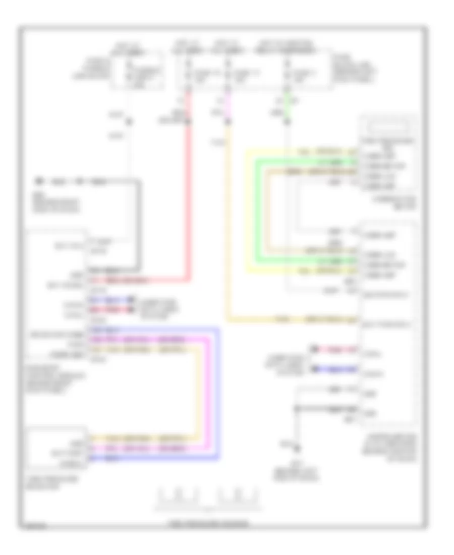
Tire Pressure Monitoring Wiring Diagram for Infiniti G37 x 2013

List of elements for Tire Pressure Monitoring Wiring Diagram for Infiniti G37 x 2013:

  • (or pnk)
  • Bat (f/l)
  • Bat (fuse)
  • Bat pwr sply
  • Battery
  • Bcm (body control module) (behind right kick panel)
  • Can-h
  • Can-l
  • Combination meter
  • Comm amp
  • Comm lcd
  • Comm meter
  • Computer data lines system
  • Fuse & fusible link block
  • Fuse 10 10a
  • Fuse 11 10a
  • Fuse 3 10a
  • Fuse block (j/b) (behind left kick panel)
  • Fusible link k 40a
  • Gnd
  • Hot at all times
  • Hot w/ ignition relay energized
  • Ign pwr sply
  • M1 2a
  • M11 (behind left end of dash)
  • M118
  • M119
  • M122
  • M123
  • M66
  • M67
  • M95 (behind right side of dash)
  • Pnk
  • Pwr
  • Receiver comm
  • Red
  • Signal
  • Snsr gnd
  • Tan
  • Tire pressure ind
  • Tire pressure receiver
  • Tire pressure sensor
  • Unified meter & a/c amplifier (behind center of dash)