ENGINE PERFORMANCE
4.5L
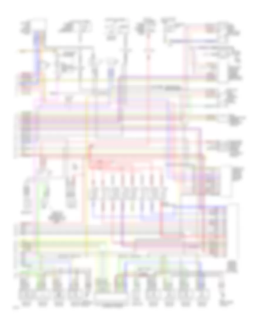
4.5L, Engine Performance Wiring Diagrams (1 of 2) for Infiniti Q45 1994

List of elements for 4.5L, Engine Performance Wiring Diagrams (1 of 2) for Infiniti Q45 1994:
- (attached to top cylinder block)
- (top front of eng)
- 10a
- 25a
- Acc
- Cam- shaft position sensor (left front of eng)
- Canister control solenoid valve (left front of eng)
- Check connector
- Cooling fans system
- Data link connector (under left side of i/p)
- Ecm relay (in left kick panel)
- Egrc solenoid valve (left front of eng)
- Engine control module (in right kick panel)
- Engine temperature sensor (left rear of eng)
- Fuse
- Fuse box (i/p)
- Fusible link & fuse box (underhood)
- G110 (left front of eng)
- G200 (left kick panel)
- Hot at all times
- Hot in start or on
- Iacv-aac valve (top rear of eng)
- Ignition switch
- Instrument cluster system (tach)
- J/c f
- Left heated oxygen sensor (on left exhaust manifold)
- Left knock sensor
- Left power transistor unit (top left of eng)
- Mass air flow sensor (left front of eng)
- Nca
- Off
- Power steering/ oil pressure switch
- Red
- Right heated oxygen sensor (on right exhaust manifold)
- Right knock sensor
- Smj
- Start
- Sub- camshaft position sensor (left front of eng)
- Vtc solenoid valve (left)
- Vtc solenoid valve (right)
- W/ tcs only
4.5L, Engine Performance Wiring Diagrams (2 of 2) for Infiniti Q45 1994
List of elements for 4.5L, Engine Performance Wiring Diagrams (2 of 2) for Infiniti Q45 1994:
- (left rear of eng)
- 15a
- 25a
- 30a
- A/t control unit (above left kick panel)
- Acc
- Check connector
- Egr temperature sensor (left rear of eng)
- Engine control module (in right kick panel)
- F11
- Fuel pump (in fuel tank)
- Fuel pump control module (under center of rear shelf)
- Fuel pump relay (left side of trunk)
- Fuel red
- Fuse
- Fuse box (i/p)
- Fusible link & fuse box (under hood)
- Fusible link & fuse box (underhood)
- G114
- G117 (right rear of eng)
- Hot at all times
- Hot in start or on
- Ignition coil #1
- Ignition coil #2
- Ignition coil #3
- Ignition coil #4
- Ignition coil #5
- Ignition coil #6
- Ignition coil #7
- Ignition coil #8
- Ignition coil relay (in right kick panel)
- Ignition switch
- Injectors
- Instrument cluster
- J/b g
- J/c f
- J/c g
- J/c h
- Mal- function indicator lamp
- Nca
- No.1
- No.2
- No.3
- No.4
- No.5
- No.6
- No.7
- No.8
- Off
- Park/neutral position relay
- Red
- Resistor
- Right power transistor unit (top right of eng)
- Secondary throttle position sensor (w/ tcs) (left front of eng)
- Smj
- Start
- Throttle control module (w/ tcs) (center of i/p)
- Throttle position sensor/switch (on throttle body)
- W/ tcs only