INSTRUMENT CLUSTER
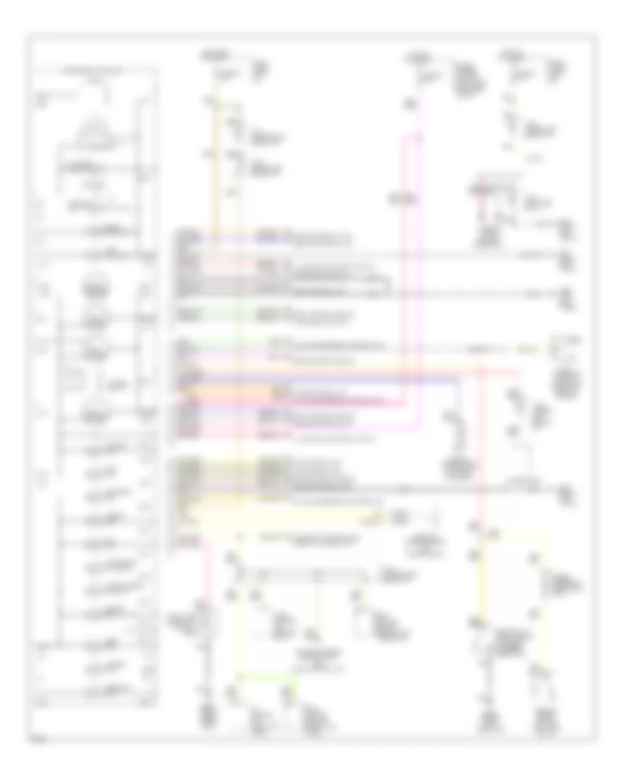
Diagnostic Display Wiring Diagram for Infiniti Q45 1994

List of elements for Diagnostic Display Wiring Diagram for Infiniti Q45 1994:
Gauges, Indicators & Clock Wiring Diagram for Infiniti Q45 1994
List of elements for Gauges, Indicators & Clock Wiring Diagram for Infiniti Q45 1994: