
HORN
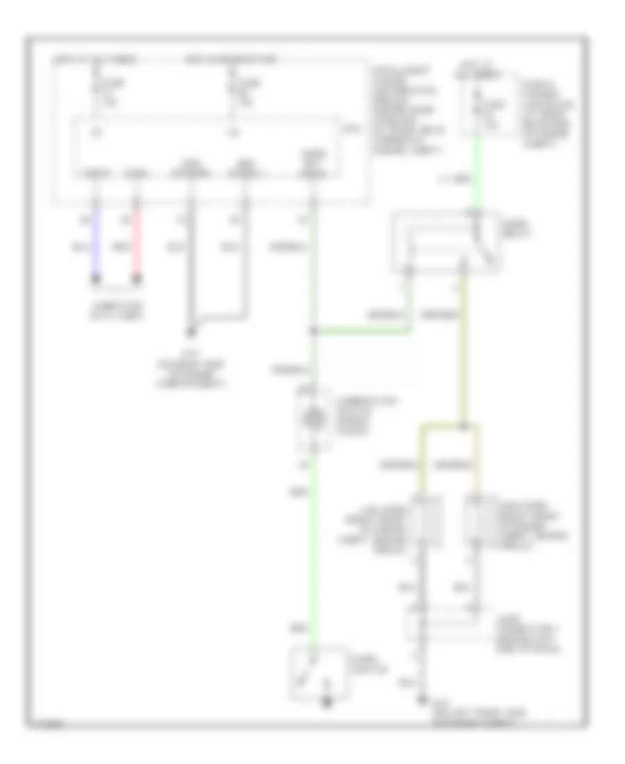
Horn Wiring Diagram for Infiniti G35 2003
List of elements for Horn Wiring Diagram for Infiniti G35 2003:
AIR CONDITIONINGBODY CONTROL MODULESANTI-LOCK BRAKESANTI-THEFTDEFOGGERSCOMPUTER DATA LINESCOOLING FANCRUISE CONTROLENGINE PERFORMANCEEXTERIOR LIGHTSGROUND DISTRIBUTIONINSTRUMENT CLUSTERHORNINTERIOR LIGHTSHEADLIGHTSPOWER DISTRIBUTIONMEMORY SYSTEMSNAVIGATIONPOWER DOOR LOCKSPOWER MIRRORSPOWER WINDOWSPOWER SEATSPOWER TOP/SUNROOFRADIOTRANSMISSIONSHIFT INTERLOCKSUPPLEMENTAL RESTRAINTSTRUNK, TAILGATE, FUEL DOORSTARTING/CHARGINGWARNING SYSTEMSWIPER/WASHER