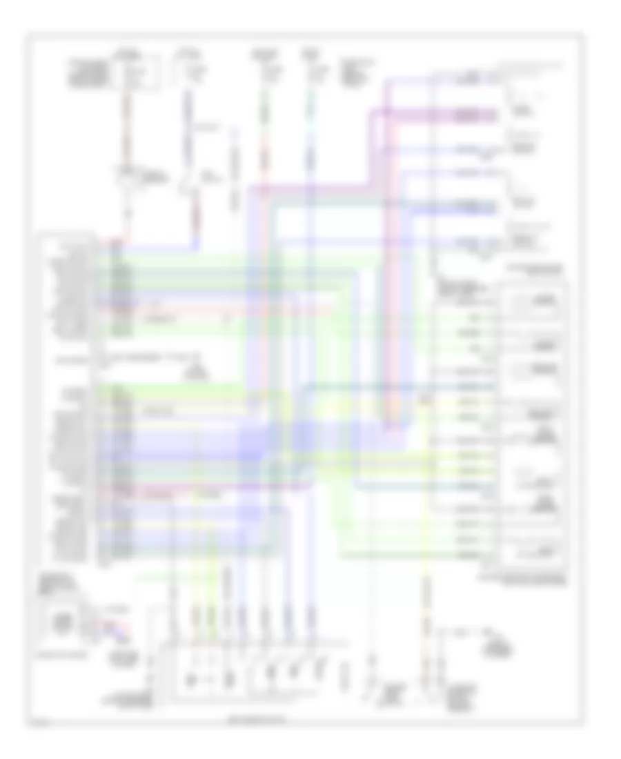
MEMORY SYSTEMS
Memory Systems Wiring Diagram for Infiniti G35 2003
List of elements for Memory Systems Wiring Diagram for Infiniti G35 2003:
- (behind instrument cluster)
- A/t device detention switch (shifter assembly)
- B29 (on left "c" pillar)
- B322
- B323
- B324
- B325
- B326
- B327
- B330
- B331
- B5 (on left front side of passenger compt floor)
- Batt (fuse)
- Batt (ptc)
- Cancel sw
- Circuit breaker
- Combination meter
- Computer data lines system
- Door sw (dr)
- Driver seat control unit (below driver seat)
- Driver's side front power seat (bottom of seat frame)
- Driver's side power seat switch
- Drivers front door switch
- Fr lift sw (up)
- Fr mtr (dwn)
- Fr mtr (up)
- Front lifting motor
- Front lifting sensor
- Frt lift switch
- Fuse & fusible link block (at right rear side of engine compartment)
- Fuse 10a
- Fuse block (j/b) (behind left kick panel)
- Fuse f 50a
- Gnd (power)
- Gnd (signal)
- Hot at all times
- Hot in on or start
- Hot in start
- Ign
- Key sw
- Key switch
- Lift sw (dwn)
- M19
- M20
- M30
- Mem 1
- Mem 2
- Memory ind1
- Memory ind2
- Memory sw1
- Memory sw2
- Park pos sw
- Pulse sw
- Pulse sw gnd
- Rear lift switch
- Rear lifting motor
- Rear lifting sensor
- Recl mtr (fr)
- Recl mtr (rr)
- Recl sw (fr)
- Recl sw (rr)
- Recline switch
- Reclining motor
- Reclining sensor
- Red
- Rr lift sw (up)
- Rr mtr (dwn)
- Rr mtr (up)
- Seat memory switch
- Set sw
- Slide switch
- Sliding motor
- Sliding mtr (fr)
- Sliding mtr (rr)
- Sliding sensor
- Sliding sw (fr)
- Sliding sw (rr)
- Speed signal
- Unified meter control unit
 English