SUPPLEMENTAL RESTRAINTS
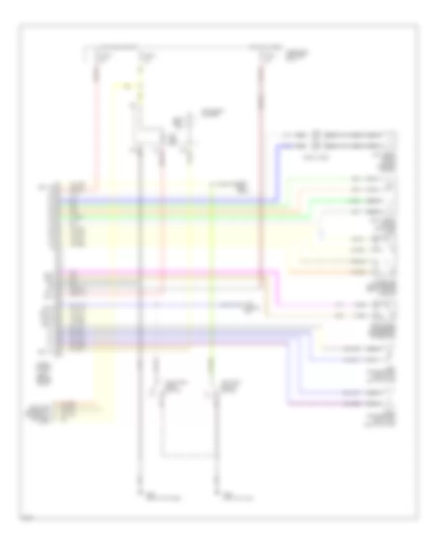
Supplemental Restraint Wiring Diagram for Infiniti G20 1995
List of elements for Supplemental Restraint Wiring Diagram for Infiniti G20 1995:
- 10a
- Air bag ind.
- Airbag control unit (below center of i/p)
- B-17
- Bat+
- Belt sw
- Belt w/l
- Czsc+
- Czsc-
- Data link connector for consult (left side of i/p)
- Dr sw
- Front crash zone sensor (center front of radiator)
- Fuse block (left side of i/p)
- Fuse h
- Fuse u
- Fuse y
- G203 (right kick panel)
- G308 (left "b" pillar)
- Gnd
- Hot at all times
- Hot in on or start
- Ign
- Ind lp
- Instrument cluster
- Left airbag module (top of steering column)
- Left front door switch
- Left pretensioner (bottom of left "b" pillar)
- Nca
- P/t+
- P/t-
- Right airbag module (right side of i/p)
- Right pretensioner (bottom of right "b" pillar)
- Seat belt buckle switch
- Seat belt ind.
- Seat belt relay
- Spiral cable
- Sq+
- Sq-
- Ss+
- Ss-
- Sss clk
- Sss rx
- Sss tx
- Time control unit
- Ts+
- Ts-
- Tunnel and safing sensor (below center console)
 English