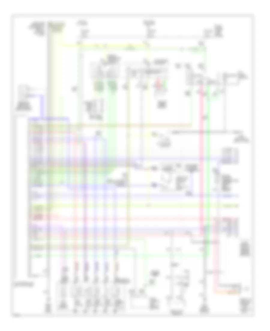
TRANSMISSION
Transmission Wiring Diagram for Infiniti G20 1995
List of elements for Transmission Wiring Diagram for Infiniti G20 1995:
- (side of transaxle) inhibitor switch
- A/t control unit (left kick panel)
- A/t fluid temp. sensor
- A/t mode switch
- All times
- Ascd control unit (behind left i/p)
- Automatic transaxle
- Closed throttle
- Cmfrt
- Comfort
- Cruise control
- Data link connector (for consult) (below left side of i/p)
- Diodes (1994 & 95) (left i/p)
- Dropping resistor (left side of engine compt)
- Eccs control module (behind center console)
- Engine coolant temperature sensor (left rear of engine)
- Exterior lights (backup)
- Fuse block (left kick panel)
- Fuse g 10a
- Fuse u 10a
- Fuse w 10a
- G114 (left rear of engine)
- G200 (left kick panel)
- G305 (bottom of left b pillar)
- Hot at
- Hot in on or start
- Instrument cluster
- Instrument cluster (tachometer)
- Line press. sol. valve
- Nca
- O.d. control
- O.d. off ind.
- Over- run clutch sol.
- Pnk
- Power
- Pwr
- Red
- Revolution sensor
- Shift sol. valve a
- Shift sol. valve b
- Speedometer
- Switch
- Tcc sol. valve
- Throttle position sensor (on throttle body)
- Throttle position switch (on throttle body)
- Vehicle speed sensor
- Wot
 English