TRANSMISSION
4WD Wiring Diagram for Hyundai Santa Fe GLS 2013

List of elements for 4WD Wiring Diagram for Hyundai Santa Fe GLS 2013:
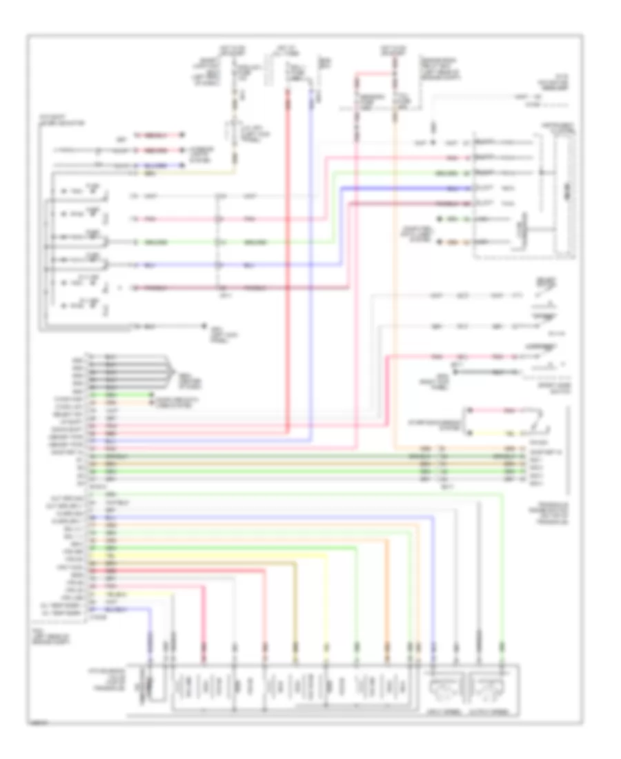
A/T Wiring Diagram for Hyundai Santa Fe GLS 2013
List of elements for A/T Wiring Diagram for Hyundai Santa Fe GLS 2013: