WARNING SYSTEMS
Chime Wiring Diagram for Hyundai Santa Fe GLS 2013

List of elements for Chime Wiring Diagram for Hyundai Santa Fe GLS 2013:
- Acc/on input
- Auto
- B-can high
- B-can low
- Bcm (center of dash)
- Buzzer
- C-can high
- C-can low
- Computer data lines system
- Cpu
- D01-a
- Door open ind
- Door open switch
- Door switch
- Driver door lock actuator (rear of driver door)
- Driver door module
- Driver seat belt buckle switch
- Driver seat belt buckle switch (in driver seat belt buckle assembly)
- Gf01 (left kick panel)
- Gf05 (under center console)
- Gm02 (left top of dash)
- Gm03 (behind center of dash)
- Head
- High
- Hot at all times
- Hot in on or acc
- Hot in on or start
- I/p-d
- I/p-e
- I/p-f
- I/p-g
- I/p-h
- Ignition key illumination & door warning switch
- Ill
- Instrument cluster
- Interface
- Ips control module
- Joint connector jm01 (left end of dash)
- Key hole ill
- Key in switch
- Leak current autocut device
- Light switch
- Low
- M01-l
- M02-a
- M02-c
- M02-d
- Memory fuse 10a
- Micom
- Module 3 fuse 10a
- Module 4 fuse 10a
- Multi-function switch
- Nca
- Off
- Pnk
- Red
- S-gnd
- Seat belt ind
- Smart junction box (left end of dash)
- Ssb ill
- Start/stop button switch
- Tail
- Tail lamp sw
- Transceiver c-can
- Transceiver ic b-can
- W/ smart key
- W/o smart key
- Warning (+)
- Warning (-)
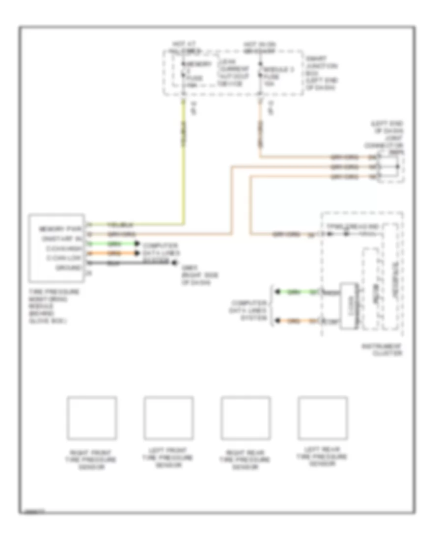
Tire Pressure Monitoring Wiring Diagram for Hyundai Santa Fe GLS 2013
List of elements for Tire Pressure Monitoring Wiring Diagram for Hyundai Santa Fe GLS 2013:
- (left end of dash) joint connector jm01
- C-can high
- C-can low
- Computer data lines system
- Gm05 (right side of dash)
- Ground
- High
- Hot at all times
- Hot in on or start
- I/p-e
- I/p-g
- Instrument cluster
- Interface
- Leak current autocut device
- Left front tire pressure sensor
- Left rear tire pressure sensor
- Low
- Memory fuse 10a
- Memory pwr
- Micom
- Module 3 fuse 10a
- On/start in
- Right front tire pressure sensor
- Right rear tire pressure sensor
- Smart junction box (left end of dash)
- Tire pressure monitoring module (behind glove box)
- Tpms tread ind
- Transceiver c-can