ANTI-LOCK BRAKES
Anti-lock Brake Wiring Diagrams for Chrysler Sebring Limited 2001
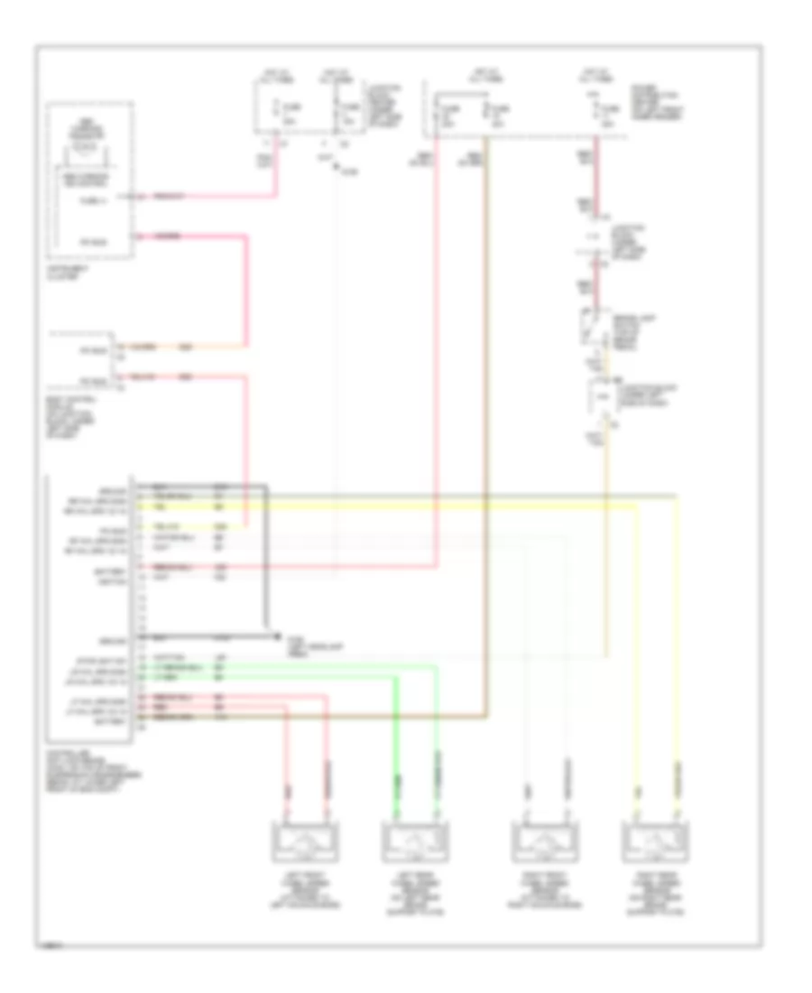
List of elements for Anti-lock Brake Wiring Diagrams for Chrysler Sebring Limited 2001:
- A10
- A20
- Abs warning ind control
- Abs warning indicator
- Battery
- Body control module (on junction block, under left side of dash)
- Brake lamp switch (top of brake pedal)
- Controller anti-lock brake (conv: on top of front suspension crossmember) sedan: at lower left front of eng compt)
- D25
- F20
- Fuse (+)
- Fuse 15a
- Fuse 20a
- Fuse 40a
- G106 (left headlamp area)
- Ground
- Hot at all times
- Ignition
- Instrument cluster
- Jucntion block center (under left side of dash)
- Junction block (under left side of dash)
- L50
- Left front wheel speed sensor (attached to left knuckle boss)
- Left rear wheel speed sensor (on left rear brake support plate)
- Lf whl spd 12v in
- Lf whl spd sign
- Lr whl spd 12v in
- Lr whl spd sign
- Pci bus
- Power distribution center (on left front inner fender)
- Red
- Rf whl spd 12v in
- Rf whl spd sign
- Right front wheel speed sensor (attached to right knuckle boss)
- Right rear wheel speed sensor (on right rear brake support plate)
- Rr whl spd 12v in
- Rr whl spd sign
- S126
- Stoplight sw
- Z101
- Z102
 English