ANTI-LOCK BRAKES
Anti-lock Brake Wiring Diagrams for Dodge Ram Van B3500 1998
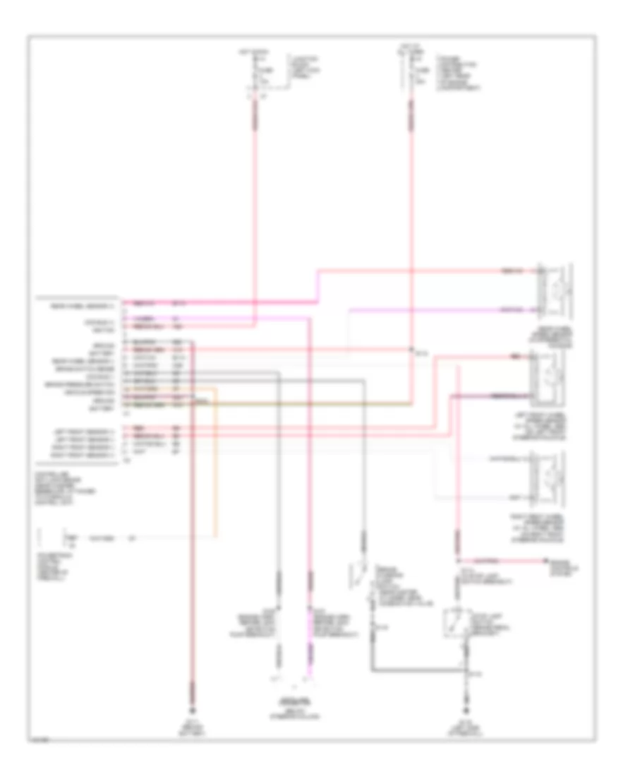
List of elements for Anti-lock Brake Wiring Diagrams for Dodge Ram Van B3500 1998:
- (below steering column)
- A10
- A20
- B113
- B114
- B27
- Battery
- Brake pressure switch
- Brake switch sense
- Brake warning lamp switch (near master cylinder, near combination valve)
- Ccd bus (+)
- Ccd bus (-)
- Controller anti-lock brake (near washer reservoir, attached to hydraulic control unit)
- Data link connector
- Engine controls system
- Fuse 10a
- Fuse 40a
- G111 (behind battery)
- G116 (left side of firewall)
- Ground
- Hot at all times
- Hot in run
- Ignition
- Junction block (left kick panel)
- K29
- Left front sensor (+)
- Left front sensor (-)
- Left front wheel speed sensor (w/ all wheel abs) (on left front steering knuckle)
- Power distribution center (left rear of engine compartment)
- Powertrain control module (center of firewall)
- Rear wheel sensor (+)
- Rear wheel sensor (-)
- Rear wheel speed sensor (in differential housing)
- Red
- Right front sensor (+)
- Right front sensor (-)
- Right front wheel speed sensor (w/ all wheel abs) (on right front steering knuckle)
- S106 (engine harn, before leak detection pump breakout)
- S107 (engine harn, before leak detection pump breakout)
- S114 (in stop lamp switch breakout)
- S115
- S118
- S119
- S122
- Stop lamp switch (brake pedal bracket)
- Vehicle speed sig
- Z22
 English