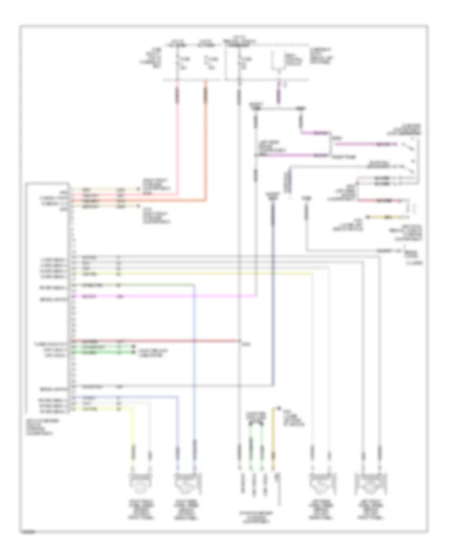
ANTI-LOCK BRAKES
Anti-lock Brakes Wiring Diagram for Dodge Sprinter 2500 2007
List of elements for Anti-lock Brakes Wiring Diagram for Dodge Sprinter 2500 2007:
- (in engine compartment) stop lamp switch
- (left rear engine compartment) s303
- (right front of engine compartment) g108
- Additional terminal 15 relay (in engine compartment)
- Anti-lock brakes module (in engine compartment)
- Base
- Body control module
- Brake lamp sw
- Brake lmp sw
- Can c bus (+)
- Can c bus (-)
- Cluster
- Computer data lines system
- Dynamics sensor (in engine compartment)
- Except base
- Fuse 25a
- Fuse 40a
- Fuse 5a
- Fuse b(+) pump
- Fuse block 1 (top of fuse/relay box)
- Fuse/relay block (behind left kick panel)
- Fused b(+) vlv
- Fused ign sw out
- G102 (right front of engine compartment)
- G301 (lower left side of vehicle)
- Gnd
- Hot at all times
- Hot w/ terminal 15 relay energized
- Ign sw out
- Left front wheel speed sensor (on left front wheel)
- Left rear wheel speed sensor (on left rear wheel)
- Lf spd sens (+)
- Lf spd sens (-)
- Lr spd sens (+)
- Lr spd sens (-)
- Rf spd sens (+)
- Rf spd sens (-)
- Right front wheel speed sensor (on right front wheel)
- Right rear wheel speed sensor (on right rear wheel)
- Rr spd sens (+)
- Rr spd sens (-)
- S328
- S329 (left rear engine compartment)
- U371
- U94
 English