COMPUTER DATA LINES
Computer Data Lines Wiring Diagram (1 of 2) for Dodge Sprinter 2500 2007

List of elements for Computer Data Lines Wiring Diagram (1 of 2) for Dodge Sprinter 2500 2007:
- (automatic a/c)
- (base)
- (in fuse/relay block) body control module
- (in roof console) roof control module
- (manual a/c)
- (sound 20)
- A/c heater control
- C11
- Can b bus (+)
- Can b bus (-)
- Can c bus (+)
- Can c bus (-)
- Data link connector (under left side dash)
- Diagnostic can c (+)
- Diagnostic can c (-)
- Diagnostic junction block 24
- Diagnostic junction block 25
- Diagnostic junction block 26
- Fuse /relay block (behind left kick panel)
- Fuse 14 5a
- Fuse 2 10a
- Fuse block 1 (top of fuse/relay box)
- G301 (lower left side of vehicle)
- Hot at all times
- Ignition switch
- Instrument cluster
- Radio
- Red
- Switch bank module
- Tire pressure monitor module (under driver's seat)
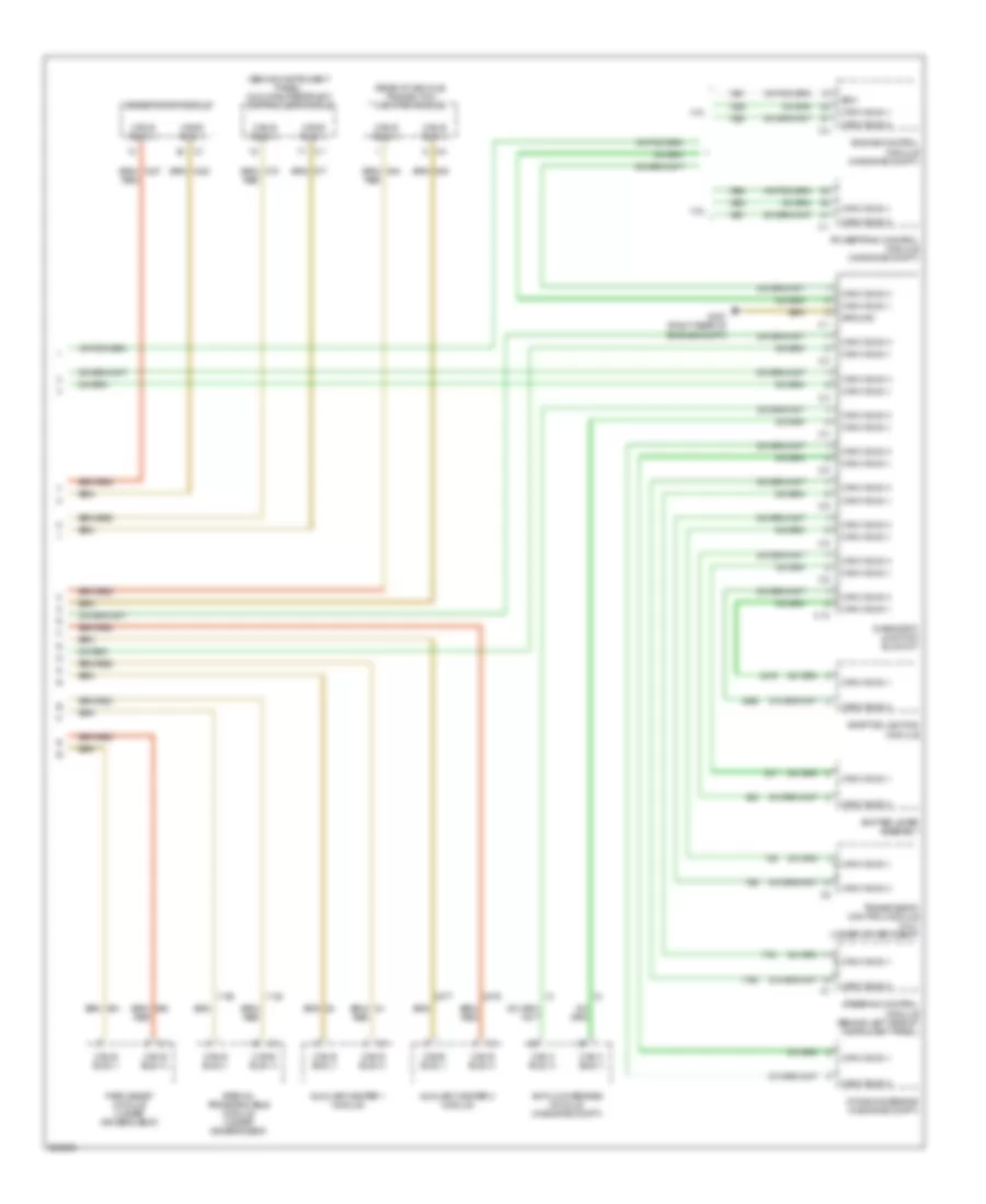
Computer Data Lines Wiring Diagram (2 of 2) for Dodge Sprinter 2500 2007
List of elements for Computer Data Lines Wiring Diagram (2 of 2) for Dodge Sprinter 2500 2007:
- (behind instrument panel) occupant restraint controller module
- (rear of vehicle) trailer tow lighting module
- 3.0l
- 3.5l
- Adaptive lighting module
- Anti-lock brakes module (in engine compt)
- Auxiliary heater 1 module
- Auxiliary heater 2 module
- C10
- Can b bus (+)
- Can b bus (-)
- Can c bus (+)
- Can c bus (-)
- Diagnostic junction block 27
- Driver door module
- Dynamics sensor (in engine compt)
- Ecm
- Engine control module (in engine compt)
- G307 (right rear of engine compt)
- Ground
- Park assist module (under driver's seat)
- Powertrain control module (in engine compt)
- Red
- Shifter lever assembly
- Special programmable module (under driver's seat)
- Steering control module (behind left side of instrument panel)
- Transmission control module (3.0l) (under driver's seat)