AIR CONDITIONING
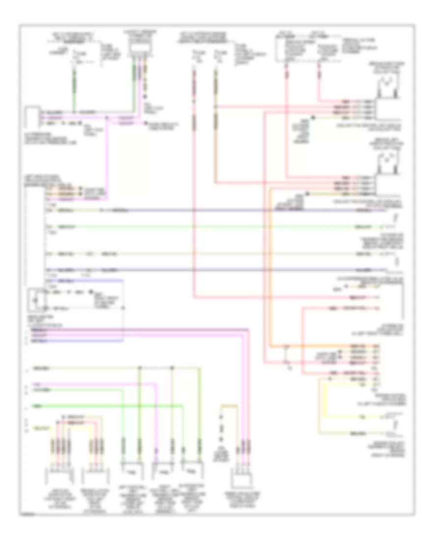
Automatic A/C Wiring Diagram, Basic (1 of 2) for Audi A7 2012

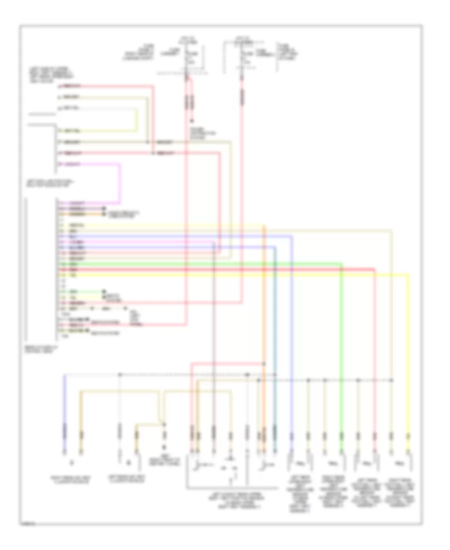
List of elements for Automatic A/C Wiring Diagram, Basic (1 of 2) for Audi A7 2012:
- (lower center of dash) g45
- Climatronic control module
- Computer data lines system
- Coolant recirculation pump (if equipped)
- Coolant shut-off valve (if equipped)
- Defroster door motor (top left side of hvac assembly)
- Fuse 10a
- Fuse 40a
- Fuse carrier
- Fuse panel c (right end of dash)
- G687 (right front of center tunnel)
- Hot at all times
- Left center vent motor (left side of hvac unit)
- Left foot well door motor
- Left temperature door motor (top left side of hvac unit)
- Left vent temperature sensor (in left side vent)
- Rear temperature door motor (lower right side of hvac unit)
- Rear temperature selection potentiometer
- Right center vent motor (right side of hvac unit)
- Right foot well door motor (right side of hvac unit)
- Right temperature door motor (top right side of hvac unit)
- Right vent temperature sensor (in right side vent)
- Sunlight photo sensor (top center of dash)
- T16p
- T17i
- T20c
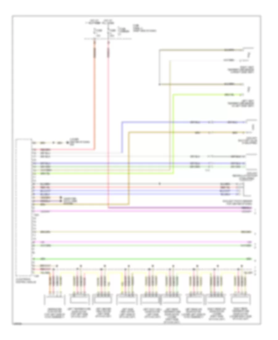
Automatic A/C Wiring Diagram, Basic (2 of 2) for Audi A7 2012
List of elements for Automatic A/C Wiring Diagram, Basic (2 of 2) for Audi A7 2012:
- (behind left side of radiator) coolant fan 2
- (behind right side of radiator) coolant fan 1
- (left end of dash) vehicle electrical system control module
- 11a
- 16a
- A/c compressor regulator valve (rear of compressor)
- A/c pressure/ temperature sensor (on a/c high pressure line)
- Air flow door motor (top right front of air intake box)
- Charge air cooling pump (in left front wheelwell)
- Computer data lines system
- Coolant fan control (fc) module (on coolant fan)
- Coolant fan control (fc) module 2 (on coolant fan 2)
- Coolant fan fuse 40a/60a/ 80a
- Engine control module (ecm) (in left plenum chamber)
- Engine coolant temperature (ect) sensor (front of engine)
- Evaporator vent temperature sensor (right side of hvac unit)
- Fresh air blower control module (lower right side of dash)
- Fuse 15a
- Fuse 5a
- Fuse carrier 1
- Fuse panel a (in left plenum chamber e-box)
- Fuse panel b (left end of dash)
- G44 (left kick panel)
- G45 (lower center of dash)
- G645
- G685 (outside of right long front member)
- G687 (right front of center tunnel)
- Hot at all times
- Humidity sensor in fresh air intake duct
- Left footwell vent temperature sensor (lower left side of hvac unit)
- Nca
- Outside air temperature sensor (behind lower right side of front grille)
- Rear center air vent illumination bulb
- Recirculation door motor (top left front of air intake box)
- Red
- Right footwell vent temperature sensor (right side of hvac assembly)
- Second speed
- T16c
- T17a
- T17d
- T32a
- T60
- T94
- Terminal 30 wire junction (in center plenum chamber)
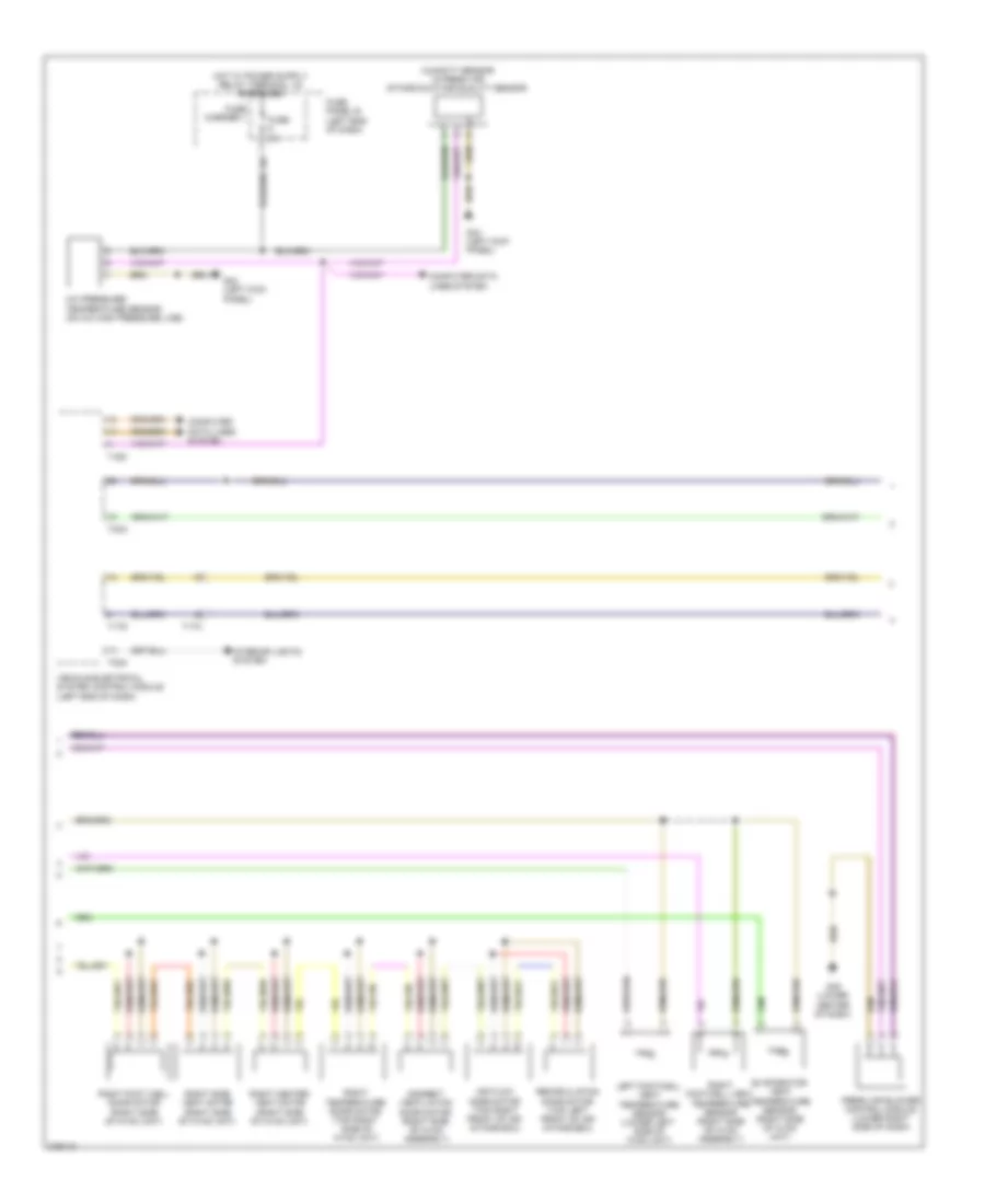
Automatic A/C Wiring Diagram, Comfort (1 of 3) for Audi A7 2012
List of elements for Automatic A/C Wiring Diagram, Comfort (1 of 3) for Audi A7 2012:
- (if equipped)
- (lower center of dash) g45
- Climatronic control module
- Computer data lines system
- Coolant recirculation pump
- Coolant shut-off valve (if equipped)
- Defroster flap motor (top left side of hvac assembly)
- Fuse 10a
- Fuse 40a
- Fuse carrier
- Fuse panel c (right end of dash)
- Hot at all times
- Left center vent motor (left side of hvac unit)
- Left foot well door motor (left side of hvac unit)
- Left rear air door motor (lower left side of hvac assembly)
- Left rear temperature door motor (lower right side of hvac unit)
- Left side vent motor (left side of of hvac unit)
- Left temperature door motor (top left side of hvac unit)
- Left vent temperature sensor (in left side vent)
- Right rear air door motor (lower right side of hvac unit)
- Right rear temperature door motor (lower right side of hvac unit)
- Right vent temperature sensor (in right side vent)
- Sunlight photo sensor (top center of dash)
- T16p
- T17i
- T20c
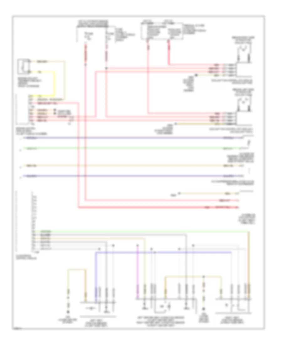
Automatic A/C Wiring Diagram, Comfort (2 of 3) for Audi A7 2012
List of elements for Automatic A/C Wiring Diagram, Comfort (2 of 3) for Audi A7 2012:
- A/c pressure/ temperature sensor (on a/c high pressure line)
- Air flow door motor (top right front of air intake box)
- Computer data lines system
- Evaporator vent temperature sensor (right side of hvac unit)
- Fresh air blower control module (lower right side of dash)
- Fuse 5a
- Fuse carrier 1
- Fuse panel b (left end of dash)
- G44 (left kick panel)
- G45 (lower center of dash)
- Humidity sensor in fresh air intake duct/air quality sensor
- Indirect ventilation door motor (right side of hvac assembly)
- Interior lights system
- Left footwell vent temperature sensor (lower left side of hvac unit)
- Recirculation door motor (top left front of air intake box)
- Right center vent motor (right side of hvac unit)
- Right foot well door motor (right side of hvac unit)
- Right footwell vent temperature sensor (right side of hvac assembly)
- Right side vent motor (right side of hvac unit)
- Right temperature door motor (top right side of hvac unit)
- T16c
- T17a
- T17d
- T32a
- Vehicle electrical system control module (left end of dash)
Automatic A/C Wiring Diagram, Comfort (3 of 3) for Audi A7 2012
List of elements for Automatic A/C Wiring Diagram, Comfort (3 of 3) for Audi A7 2012:
- (behind left side of radiator) coolant fan 2
- (behind right side of radiator) coolant fan 1
- 11a
- 16a
- A/c compressor regulator valve (rear of compressor)
- Charge air cooling pump (in left front wheelwell)
- Climatronic control module
- Computer data lines system
- Coolant fan control (fc) module (on coolant fan)
- Coolant fan control (fc) module 2 (on coolant fan 2)
- Coolant fan fuse 40a/60a/ 80a
- Engine control module (ecm) (in left plenum chamber)
- Engine coolant temperature (ect) sensor (front of engine)
- Fuse 15a
- Fuse 5a
- Fuse panel a (in left plenum chamber e-box)
- G45 (lower center of dash)
- G645
- G685 (outside of right front long member)
- Hot at all times
- Left center vent in position sensor (in left center vent) right center vent in position sensor (in right center vent)
- Left vent position sensor (in left side vent)
- Nca
- Outside air temperature sensor (behind lower right side of front grille)
- Red
- Right vent position sensor (in right side vent)
- Second speed
- T16f
- T60
- T94
- Terminal 30 wire junction (in center plenum chamber)
Rear A/C Wiring Diagram for Audi A7 2012
List of elements for Rear A/C Wiring Diagram for Audi A7 2012:
- (in rear upper body vent assembly)
- (left side of upper body vent assembly) left rear upper body vent motor
- 11a
- Computer data lines system
- Fuse 10a
- Fuse 30a
- Fuse carrier 1
- Fuse carrier 2
- Fuse panel b (left end of dash)
- Fuse panel f (right rear of luggage compt)
- G44 (left kick panel)
- G687 (right front of center tunnel)
- Hot at all times
- Left & right rear upper body vent position sensor
- Left b-pillar /footwell shut-off door motor
- Left rear air vent illumination bulb
- Left rear footwell vent temperature sensor (in left rear footwell vent assembly)
- Left rear upper body vent temperature sensor (in rear upper body vent assembly)
- Power distribution system
- Rear a/c display control head
- Red
- Right rear air vent illumination bulb
- Right rear footwell vent temperature sensor (in right rear footwell vent assembly)
- Right rear upper body vent temperature sensor (in rear upper body vent assembly)
- Seats
- Seats system
- System
- T20a
- T3r