AIR CONDITIONING
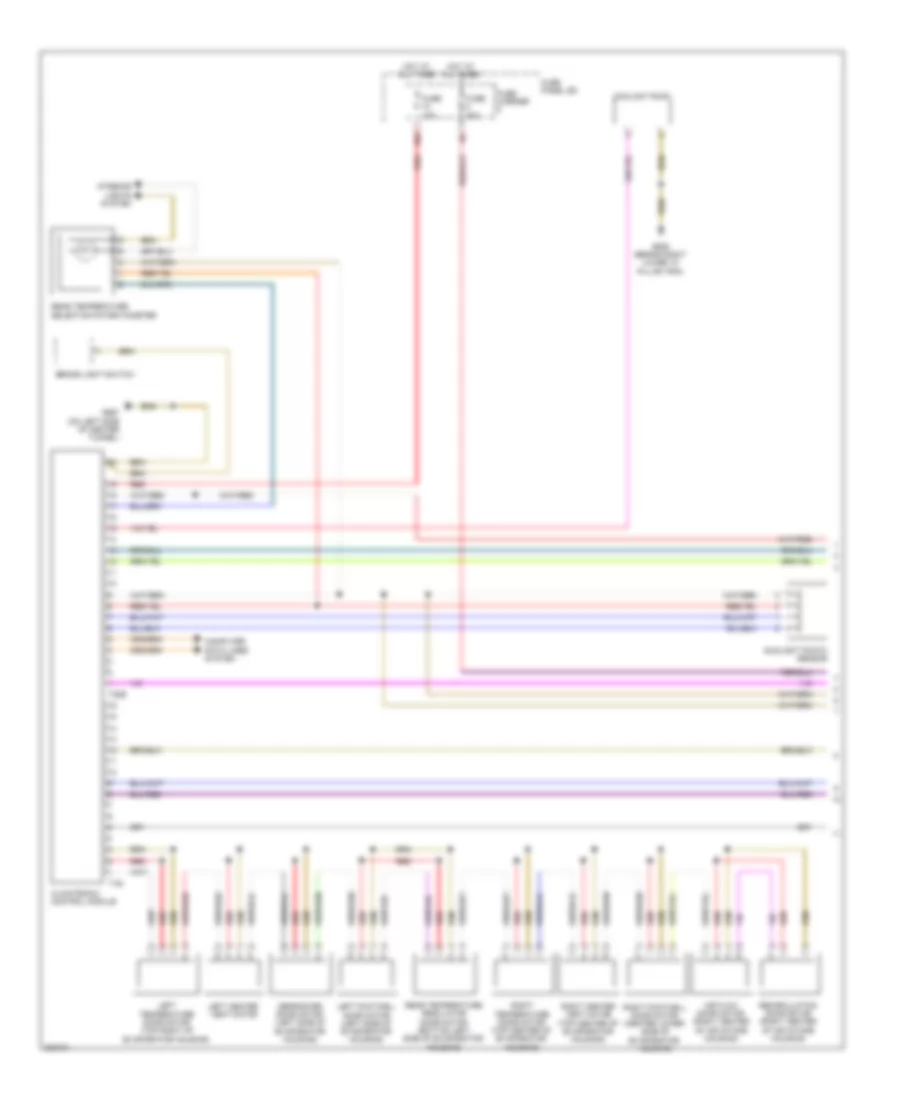
Automatic A/C Wiring Diagram, Basic (1 of 2) for Audi Q5 2010

List of elements for Automatic A/C Wiring Diagram, Basic (1 of 2) for Audi Q5 2010:
- (on left side of center tunnel) g687
- 10a
- Air flow door motor (right center of air intake housing)
- Brake light switch
- Center outlet temperature sensor
- Center vent adjustment motor
- Climatronic control module
- Climatronic refrigerant shut-off valve (rear center of engine compt)
- Computer data lines system
- Coolant pump
- Defroster door motor (left side of evaporator housing)
- Evaporator vent temperature sensor (right side of evaporator housing)
- Footwell flap motor
- Footwell outlet temperature sensor
- Fuse 10a
- Fuse 40a
- Fuse carrier
- Fuse panel sd
- G638 (behind right lower "a" pillar trim)
- Hot at all times
- Recirculation door motor (right center of air intake housing)
- Red
- Sunlight photo sensor
- T16i
- T20e
- Temperature regulator flap motor
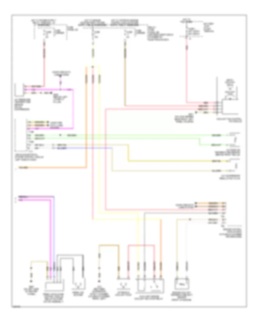
Automatic A/C Wiring Diagram, Basic (2 of 2) for Audi Q5 2010
List of elements for Automatic A/C Wiring Diagram, Basic (2 of 2) for Audi Q5 2010:
- (400w) (600w)
- (600w) coolant fan 2
- 11a
- 12a
- A/c compressor regulator valve
- A/c pressure/ temperature sensor (on a/c compressor)
- After-run coolant pump
- Auxiliary engine coolant (ec) pump relay
- Battery jump start terminal
- Computer data lines system
- Coolant fan
- Coolant fan control (fc) module
- Engine control module (ecm) (in plenum chamber driver's side)
- Engine coolant temperature (ect) sensor (front of engine)
- Fresh air blower
- Fresh air blower control module (below blower motor assembly)
- Fuse 1 40a 60a
- Fuse 15a
- Fuse 5a
- Fuse carrier
- Fuse panel sc
- G12 (between suspension strut chamber & plenum chamber front left)
- G639 (behind left lower "a" pillar)
- G671 (on long member near front left wheel housing)
- G687 (on left side of center tunnel)
- Hot at all times
- Nca
- Outside air temperature sensor (behind front grille)
- Red
- Relay/ fuse panel sb (driver's side plenum chamber on electronics box)
- T16b
- T17i
- T32b
- T60
- T94
- Vehicle electrical system control module (left side of dash)
Automatic A/C Wiring Diagram, Comfort (1 of 3) for Audi Q5 2010
List of elements for Automatic A/C Wiring Diagram, Comfort (1 of 3) for Audi Q5 2010:
- 10a
- Air flow door motor (right center of air intake housing)
- Brake light switch
- Climatronic control module
- Computer data lines system
- Coolant pump
- Defroster door motor (left side of evaporator housing)
- Fuse 10a
- Fuse 40a
- Fuse carrier
- Fuse panel sd
- G638 (behind right lower "a" pillar trim)
- G687 (on left side of center tunnel)
- Hot at all times
- Interior lights system
- Left center vent motor
- Left footwell door motor (left side of evaporator housing)
- Left temperature door motor (top right of evaporator housing)
- Rear temperature regulator door motor (bottom left side of evaporator housing)
- Rear temperature selection potentiometer
- Recirculation door motor (right center of air intake housing)
- Red
- Right center vent motor (top center of evaporator housing)
- Right footwell door motor (center lower side of evaporator housing)
- Right temperature door motor (top center of evaporator housing)
- Sunlight photo sensor
- T16i
- T20e
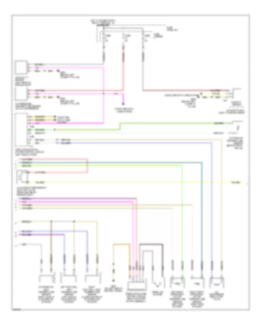
Automatic A/C Wiring Diagram, Comfort (2 of 3) for Audi Q5 2010
List of elements for Automatic A/C Wiring Diagram, Comfort (2 of 3) for Audi Q5 2010:
- 12a
- A/c compressor regulator valve
- A/c pressure/ temperature sensor (on a/c compressor)
- Air quality sensor (left rear of engine compt)
- Automatic day/ night interior mirror
- Climatronic refrigerant shut-off valve (rear center of engine compt)
- Computer data lines system
- Evaporator vent temperature sensor (right side of evaporator housing)
- Fresh air blower
- Fresh air blower control module (below blower motor assembly)
- Fuse 5a
- Fuse carrier
- Fuse panel sc
- G639 (behind left lower "a" pillar)
- G687 (on left side of center tunnel)
- Humidity sensor
- Left footwell vent temperature sensor (left side of evaporator housing)
- Left front upper body outlet temperature sensor (left side of dash)
- Nca
- Outside air temperature sensor (behind front grille)
- Right footwell vent temperature sensor (lower center of evaporator housing)
- Right front upper body outlet temperature sensor (right side of dash)
- T16b
- T17i
- T32b
- T8c
- Vehicle electrical system control module (left side of dash)
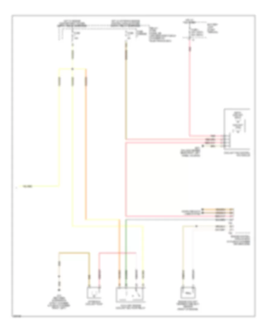
Automatic A/C Wiring Diagram, Comfort (3 of 3) for Audi Q5 2010
List of elements for Automatic A/C Wiring Diagram, Comfort (3 of 3) for Audi Q5 2010:
- (400w) (600w)
- (600w) coolant fan 2
- 11a
- After-run coolant pump
- Auxiliary engine coolant (ec) pump relay
- Battery jump start terminal
- Computer data lines system
- Coolant fan
- Coolant fan control (fc) module
- Engine control module (ecm) (in plenum chamber driver's side)
- Engine coolant temperature (ect) sensor (front of engine)
- Fuse 1 40a 60a
- Fuse 15a
- Fuse 5a
- Fuse carrier
- G12 (between suspension strut chamber & plenum chamber front left)
- G671 (on long member near front left wheel housing)
- Hot at all times
- Red
- Relay/ fuse panel sb (driver's side plenum chamber on electronics box)
- T60
- T94
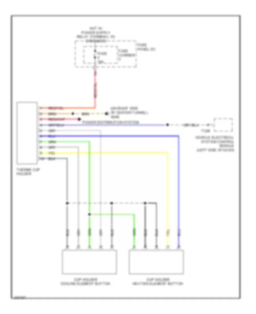
Heated And Cooled Cup Holder Wiring Diagram for Audi Q5 2010
List of elements for Heated And Cooled Cup Holder Wiring Diagram for Audi Q5 2010:
- (on right side of center tunnel) g688
- Cup holder cooling element button
- Cup holder heating element button
- Fuse 10a
- Fuse carrier
- Fuse panel sc
- Power distribution system
- T32b
- Thermo cup holder
- Vehicle electrical system control module (left side of dash)