AIR CONDITIONING
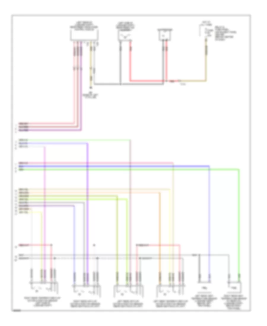
Automatic A/C Wiring Diagram (1 of 4) for Audi Q7 3.0T 2011

List of elements for Automatic A/C Wiring Diagram (1 of 4) for Audi Q7 3.0T 2011:
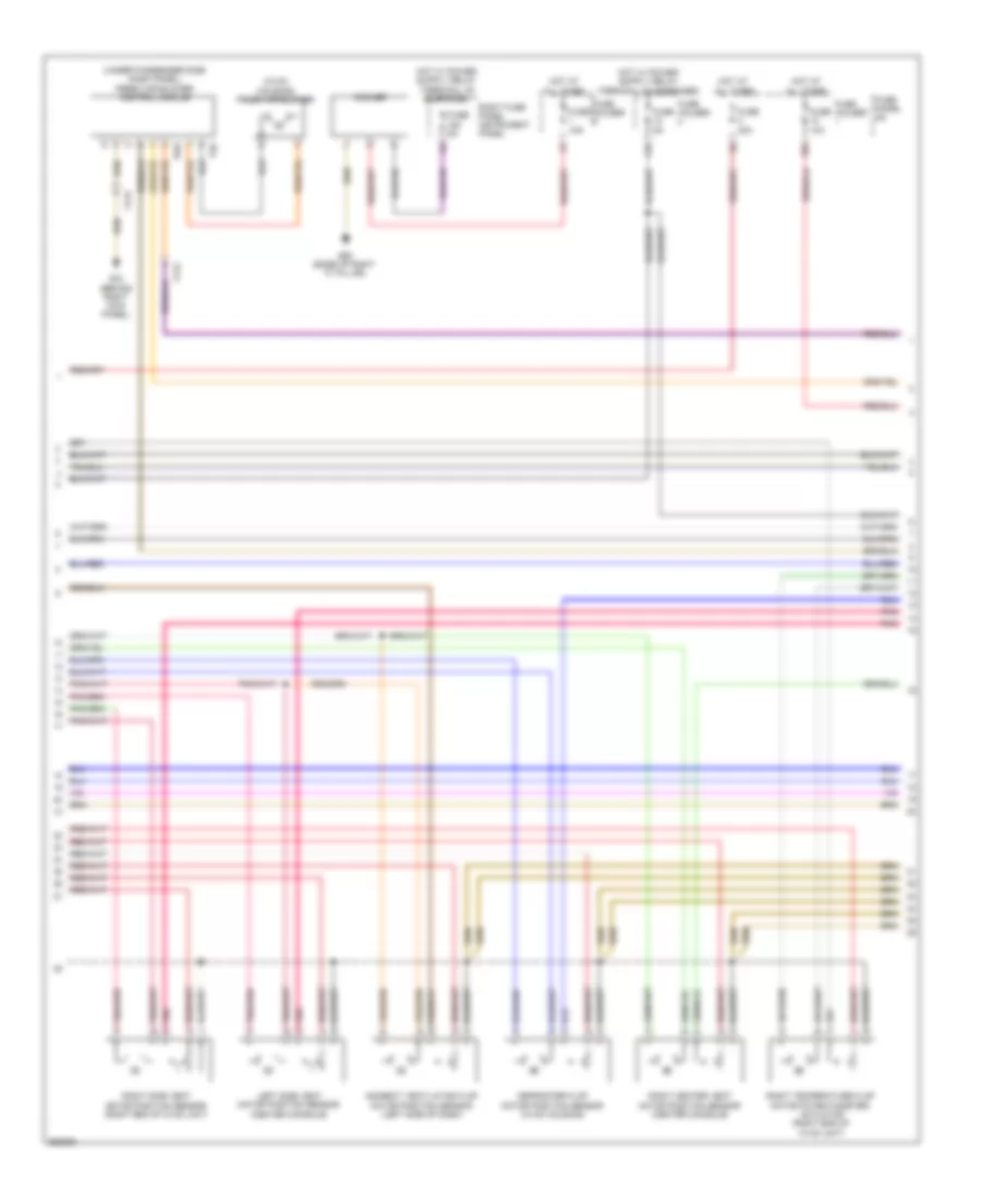
Automatic A/C Wiring Diagram (2 of 4) for Audi Q7 3.0T 2011
List of elements for Automatic A/C Wiring Diagram (2 of 4) for Audi Q7 3.0T 2011:
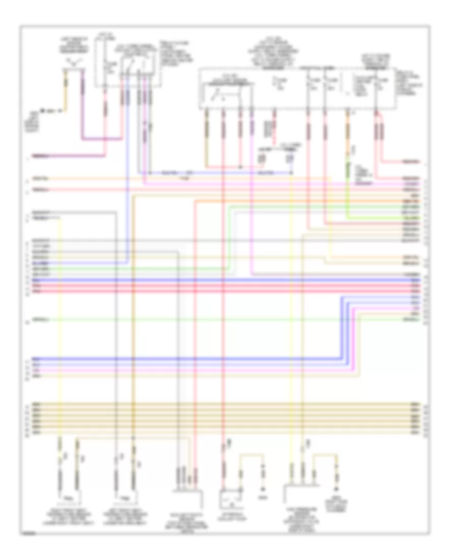
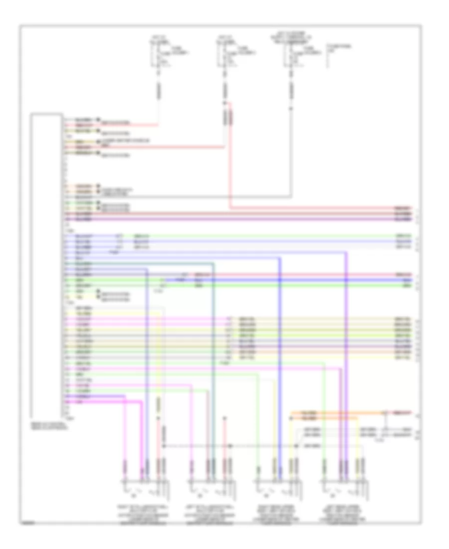
Automatic A/C Wiring Diagram (3 of 4) for Audi Q7 3.0T 2011
List of elements for Automatic A/C Wiring Diagram (3 of 4) for Audi Q7 3.0T 2011:
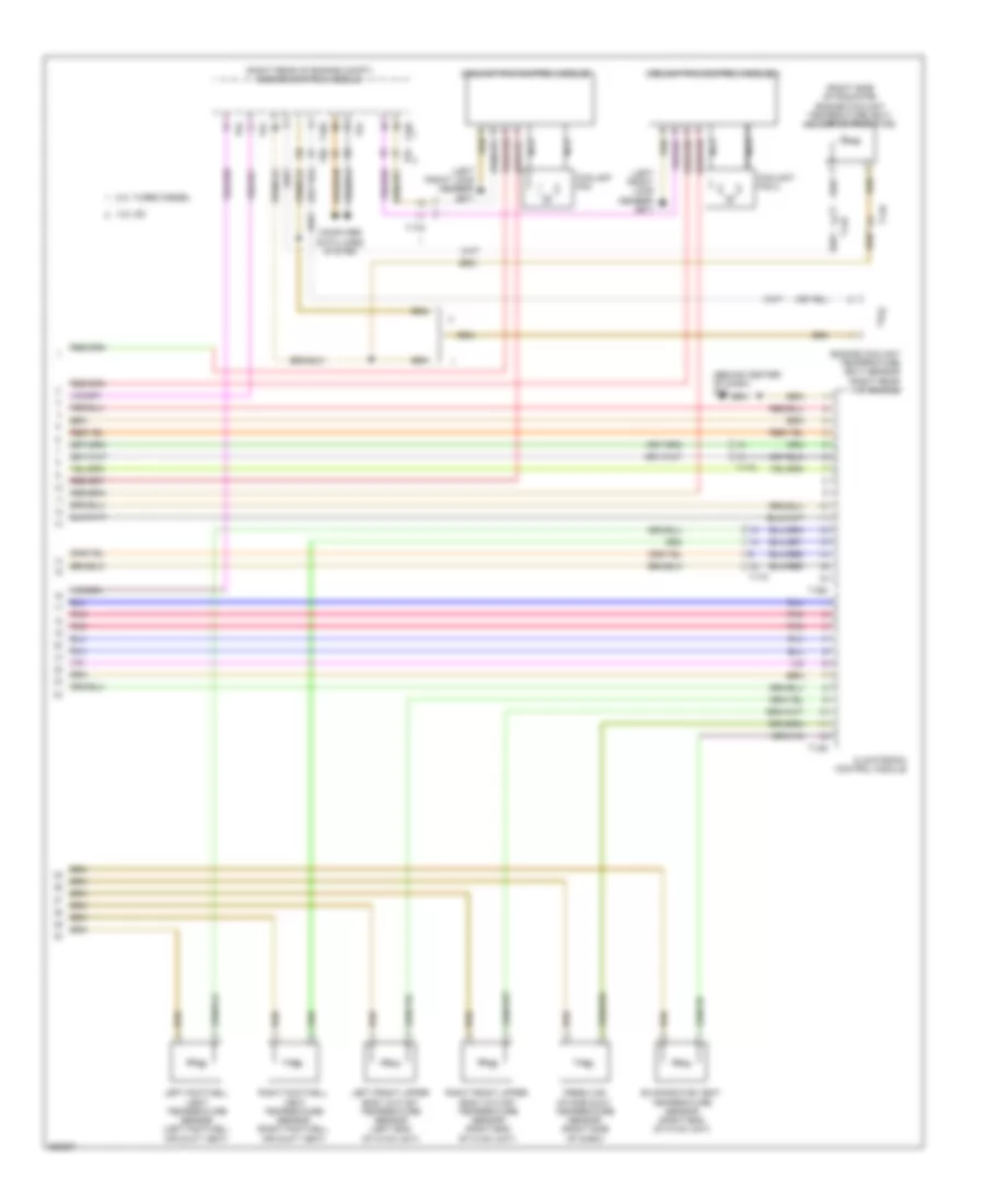
Automatic A/C Wiring Diagram (4 of 4) for Audi Q7 3.0T 2011
List of elements for Automatic A/C Wiring Diagram (4 of 4) for Audi Q7 3.0T 2011:
Rear A/C Wiring Diagram (1 of 2) for Audi Q7 3.0T 2011
List of elements for Rear A/C Wiring Diagram (1 of 2) for Audi Q7 3.0T 2011:
Rear A/C Wiring Diagram (2 of 2) for Audi Q7 3.0T 2011
List of elements for Rear A/C Wiring Diagram (2 of 2) for Audi Q7 3.0T 2011: