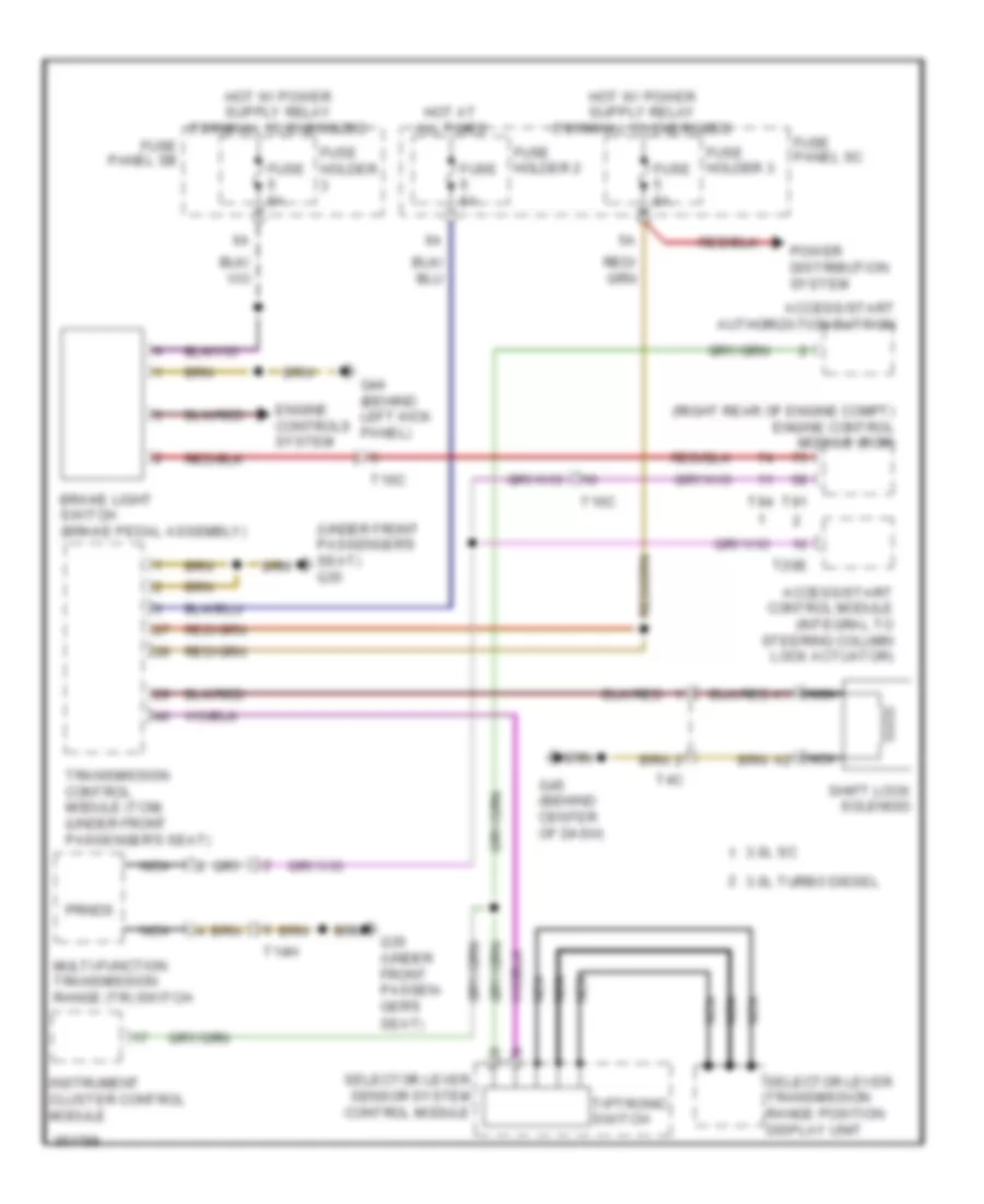
SHIFT INTERLOCK
Shift Interlock Wiring Diagram for Audi Q7 3.0T 2011
List of elements for Shift Interlock Wiring Diagram for Audi Q7 3.0T 2011:
- (right rear of engine compt) engine control module (ecm)
- (under front passenger's seat) g35
- 3.0l sc
- 3.0l turbo diesel
- Access/start authorization buttion
- Access/start control module (integral to steering column lock actuator)
- Brake light switch (brake pedal assembly)
- Engine controls system
- Fuse 5a
- Fuse holder
- Fuse holder 2
- Fuse holder 3
- Fuse panel sb
- Fuse panel sc
- G35 (under front passen- ger's
- G44 (behind left kick panel)
- G45 (behind center of dash)
- Hot at all times
- Instrument cluster control module
- Multi-function transmission range (tr) switch
- Nca
- Power distribution system
- Prnds
- Seat)
- Selector lever sensor system control module
- Selector lever transmission range position display unit
- Shift lock solenoid
- T10c
- T14h
- T20e
- T4c
- T91
- T94
- Tiptronic switch
- Transmission control module (tcm) (under front passenger's seat)
 English