ANTI-LOCK BRAKES
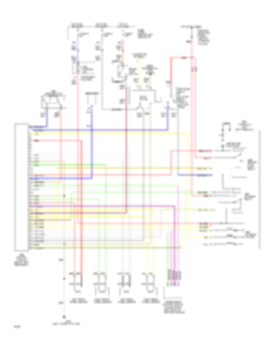
Anti-Lock Brakes Wiring Diagram for Audi 100 S 1994

List of elements for Anti-Lock Brakes Wiring Diagram for Audi 100 S 1994:
- (below left
- (left firewall)
- (lower left "a" pillar)
- 10a
- 15a
- 21a
- Abs
- Abs combi relay (in auxiliary relay panel 2, left kick panel)
- Abs return flow pump
- Abs return flow pump relay
- Abs solenoid relay
- Abs solenoid valves
- Abs warning ind.
- All times
- Brake lamp switch
- Central electric panel (left of steering column)
- Connector station 1
- Control
- Fuse 15 5a
- Fuse 21 15a
- Fuse 9 10a
- Fuse panel (behind left side of i/p)
- G200
- Generator
- Hot at
- Hot at all times
- Hot in on or start
- Hydraulic
- Instrument cluster
- Left front wheel sensor
- Left rear wheel sensor
- Module
- Nca
- Rear seat)
- Red
- Red red
- Right front wheel sensor
- Right rear wheel sensor
- Solid state
- Unit
Anti-Lock Brakes Wiring Diagram, Quattro for Audi 100 S 1994
List of elements for Anti-Lock Brakes Wiring Diagram, Quattro for Audi 100 S 1994:
- (in electronic box, right of center console)
- (left firewall)
- (left lower "a" pillar)
- 15a
- 21a
- Abs
- Abs acceleration switch
- Abs combi relay (in
- Abs control module (below left rear seat)
- Abs return flow pump
- Abs return flow pump relay
- Abs solenoid relay
- Abs solenoid valves
- Abs warning ind.
- All times
- Auxiliary relay panel 2, left kick panel)
- Brake lamp switch
- Central electric panel (left of steering
- Column)
- Connector station 1
- Control module
- Fuse 15 5a
- Fuse 21 15a
- Fuse 9 10a
- Fuse panel (behind left side of i/p)
- G200
- Generator
- Hot at
- Hot at all times
- Hot in on or start
- Hydraulic
- Instrument cluster
- Left front wheel sensor
- Left rear wheel sensor
- Nca
- Rear differential lock switch
- Red
- Red red
- Right front wheel sensor
- Right rear wheel sensor
- Solid state
- Transmission
- Unit