
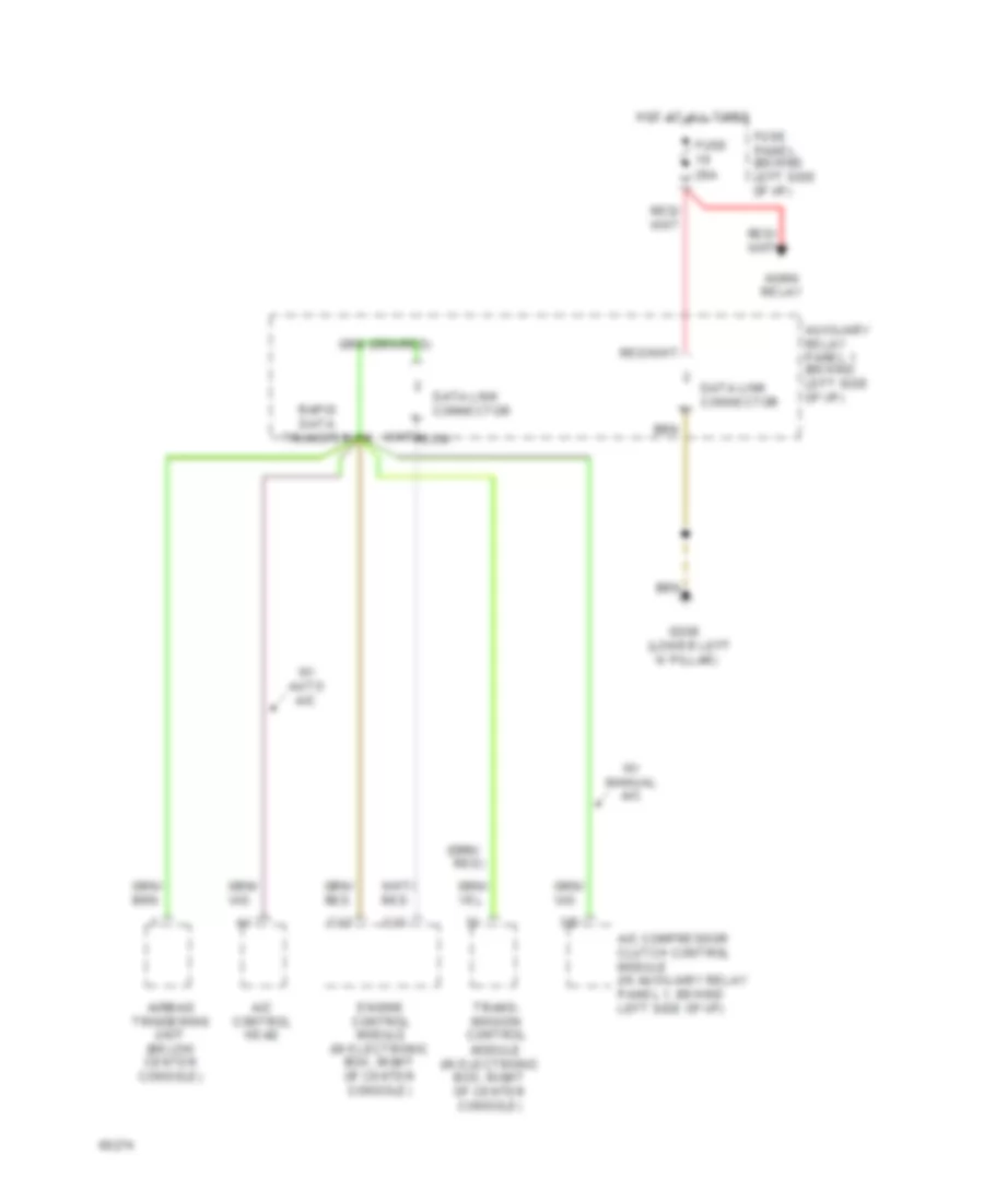
COMPUTER DATA LINES
Data Link Connector Wiring Diagram for Audi 100 S 1994
List of elements for Data Link Connector Wiring Diagram for Audi 100 S 1994:
AIR CONDITIONINGANTI-THEFTANTI-LOCK BRAKESCOOLING FANCRUISE CONTROLELECTRONIC POWER STEERINGEXTERIOR LIGHTSDEFOGGERSINSTRUMENT CLUSTERENGINE PERFORMANCEHORNCOMPUTER DATA LINESGROUND DISTRIBUTIONHEADLIGHTSINTERIOR LIGHTSPOWER DISTRIBUTIONPOWER TOP/SUNROOFPOWER SEATSMEMORY SYSTEMSPOWER WINDOWSPOWER MIRRORSPOWER DOOR LOCKSSUPPLEMENTAL RESTRAINTSSHIFT INTERLOCKSTARTING/CHARGINGWARNING SYSTEMSTRANSMISSIONRADIOTRUNK, TAILGATE, FUEL DOORWIPER/WASHER