ANTI-LOCK BRAKES
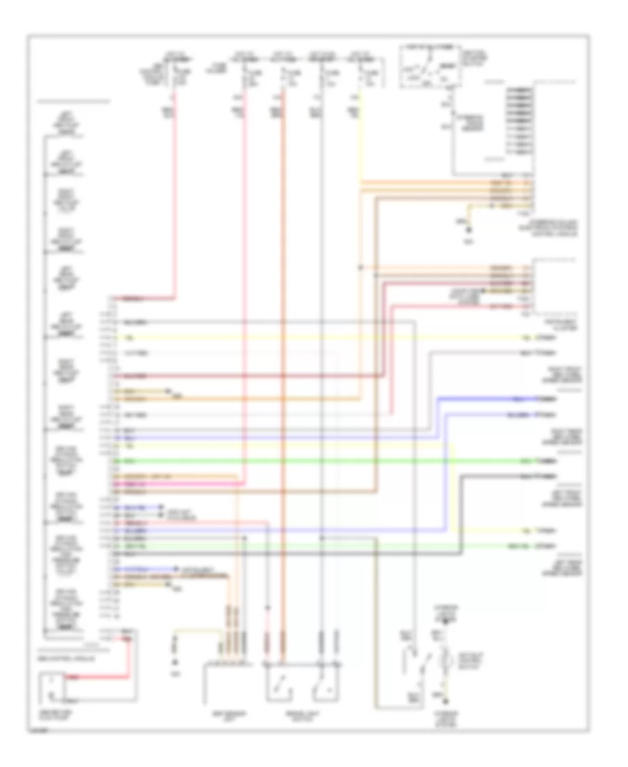
Anti-lock Brakes Wiring Diagram, without Convertible Early Production, with Convertible for Audi A4 2005

List of elements for Anti-lock Brakes Wiring Diagram, without Convertible Early Production, with Convertible for Audi A4 2005:
Anti-lock Brakes Wiring Diagram, without Convertible Late Production for Audi A4 2005
List of elements for Anti-lock Brakes Wiring Diagram, without Convertible Late Production for Audi A4 2005: