ENGINE PERFORMANCE
1.8L
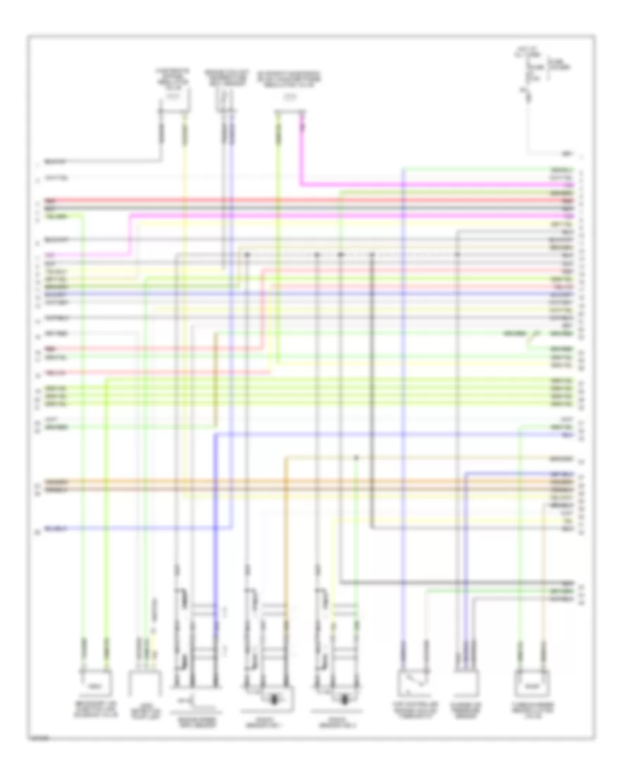
1.8L, Engine Performance Wiring Diagram (1 of 4) for Audi A4 2005

List of elements for 1.8L, Engine Performance Wiring Diagram (1 of 4) for Audi A4 2005:
- Acc
- Accelerator pedal position (app) sensor
- Brake- light switch
- Clutch vacuum vent valve switch (m/t)
- Cooling fans system
- E-box relay carrier
- Fuse 10a
- Fuse 15a
- Fuse 40a
- Fuse holder
- G12
- Generator
- Heated oxygen sensor
- Hot at all times
- Hot in run or start
- Ignition switch
- Lock
- Mass airflow (maf) sensor
- Motronic engine control module
- Off
- Oxygen sensor behind twc
- Red
- Run
- Secondary air injection (air) pump relay
- Secondary air injection pump motor
- Start
- Steering column electronic systems control module
- T16a
- Transmission control module (w/ cvt)
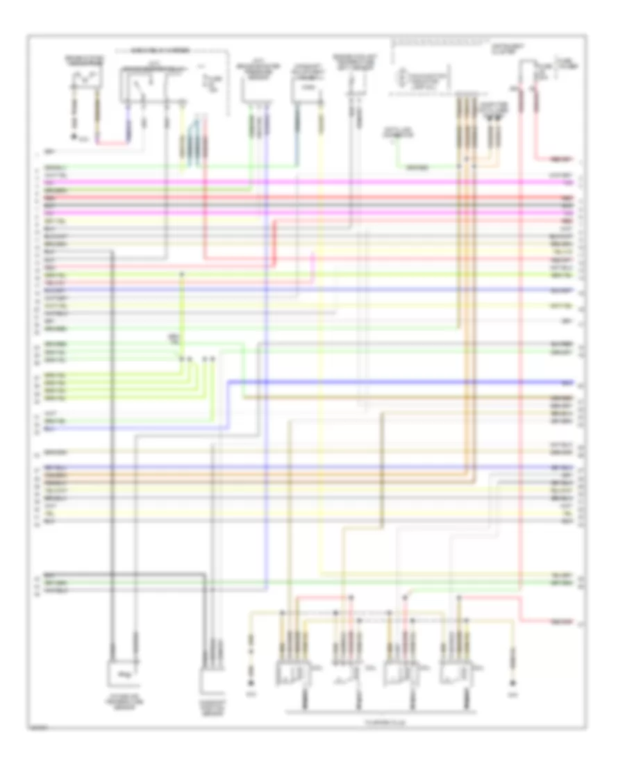
1.8L, Engine Performance Wiring Diagram (2 of 4) for Audi A4 2005
List of elements for 1.8L, Engine Performance Wiring Diagram (2 of 4) for Audi A4 2005:
- Charge air pressure sensor
- Engine coolant temperature (ect) sensor
- Engine speed (rpm) sensor
- Evaporative emission (evap) canister purge regulator valve
- Fuse 15a
- Fuse holder
- Hot at all times
- Knock sensor (ks) 1
- Knock sensor (ks) 2
- Leak detection pump (ldp)
- Map controlled engine cooling thermostat
- Nca
- Red
- Secondary air injection (air) solenoid valve
- Turbocharger recirculating valve
- Wastegate bypass regulator valve
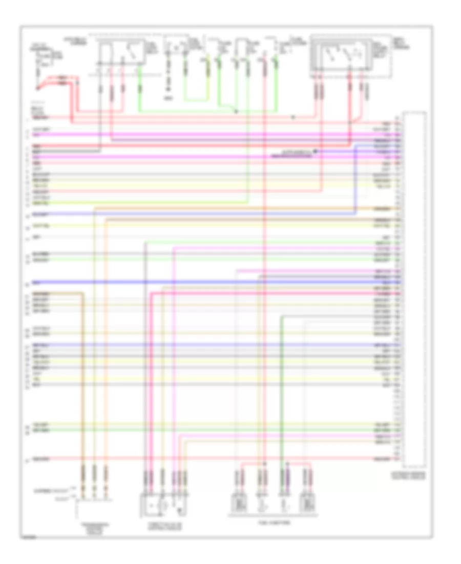
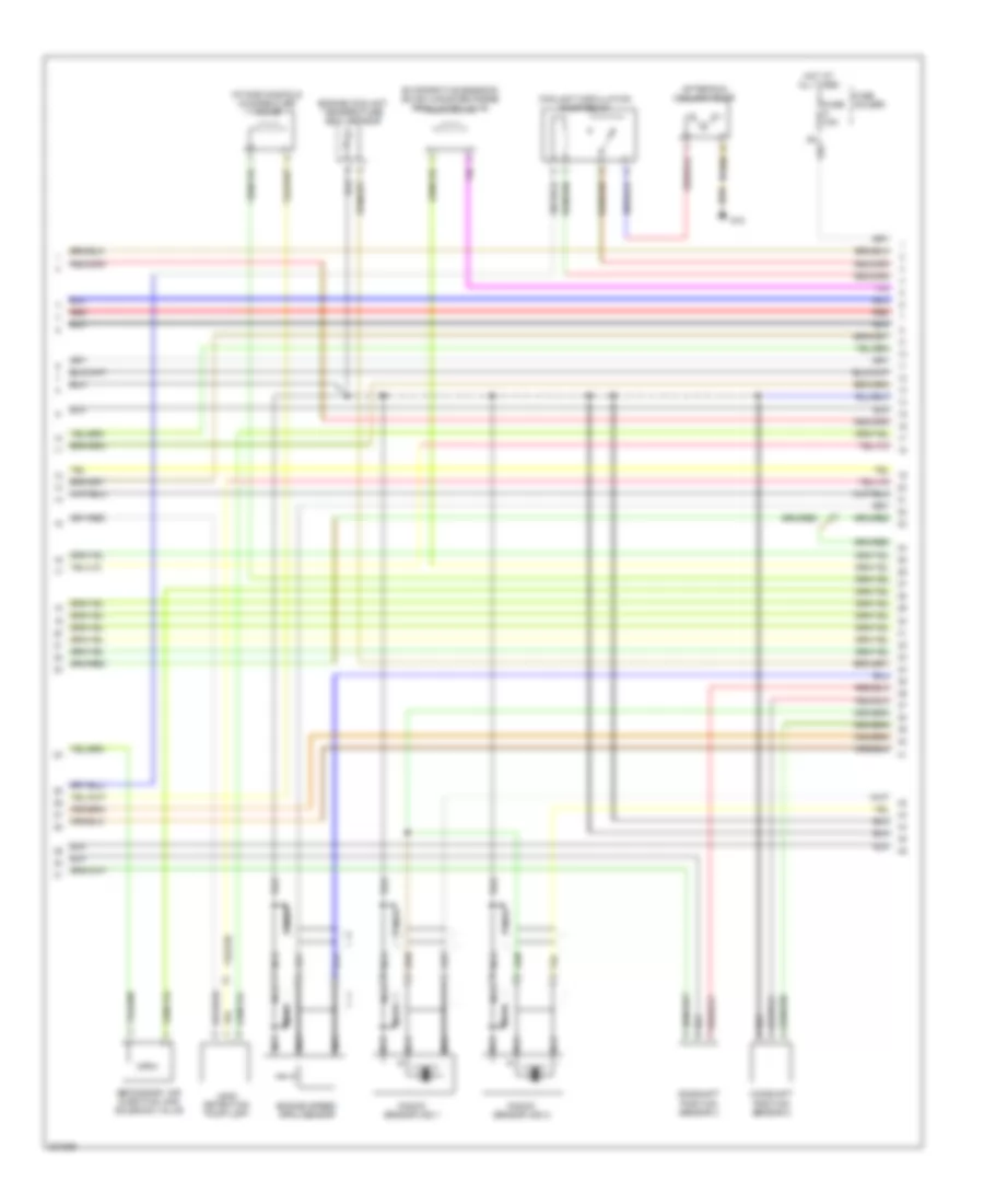
1.8L, Engine Performance Wiring Diagram (3 of 4) for Audi A4 2005
List of elements for 1.8L, Engine Performance Wiring Diagram (3 of 4) for Audi A4 2005:
- (a/t) brake booster pressure sensor
- (a/t) brake booster relay
- (mil)
- Brake system vacuum pump
- Camshaft adjustment valve 1
- Camshaft position sensor
- Coil
- Computer data lines system
- Data link connector
- E-box relay carrier
- Engine coolant temperature (ect) sensor
- Fuse 15a
- Fuse 20a
- Fuse holder
- G12
- G18
- Instrument cluster
- Intake air temperature sensor
- Malfunction indicator lamp
- Nca
- Red
- T32a/12
- T32a/13
- T32a/23
- To spark plug
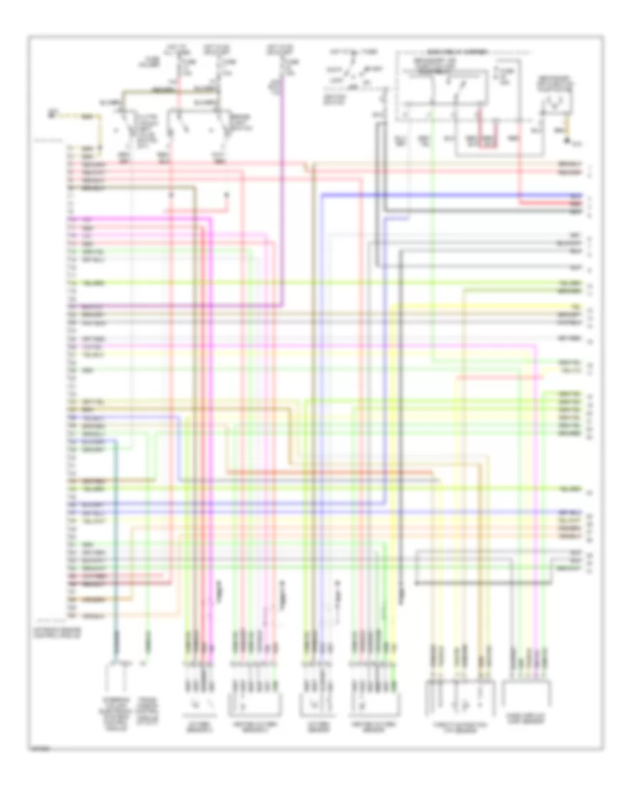
1.8L, Engine Performance Wiring Diagram (4 of 4) for Audi A4 2005
List of elements for 1.8L, Engine Performance Wiring Diagram (4 of 4) for Audi A4 2005:
- (5-speed) w/o cvt
- 9-pin relay carrier
- E-box relay carrier
- Fuel injectors
- Fuel pump motor
- Fuel pump relay
- Fuse 150a
- Fuse 15a
- Fuse 20a
- Fuse holder
- G663
- Hot at all times
- Main fuse
- Motronic engine control module
- Red
- Relay plate
- Throttle valve control module
- Transmission control module
- W/ cvt
3.0L
3.0L, Engine Performance Wiring Diagram (1 of 4) for Audi A4 2005
List of elements for 3.0L, Engine Performance Wiring Diagram (1 of 4) for Audi A4 2005:
- 14a
- Acc
- Brake- light switch
- Clutch vacuum vent valve switch (m/t)
- E-box relay carrier
- Fuse 10a
- Fuse 15a
- Fuse 40a
- Fuse holder
- G12
- Heated oxygen sensor
- Heated oxygen sensor 2
- Hot at all times
- Hot in on or start
- Ignition switch
- Lock
- Mass airflow (maf) sensor
- Motronic engine control module
- Off
- Oxygen sensor
- Oxygen sensor 2
- Red
- Secondary air injection (air) pump relay
- Secondary air injection pump motor
- Start
- Steering column electronic systems control module
- T16a
- Throttle position (tp) sensor
- Trans- mission control module (w/ cvt)
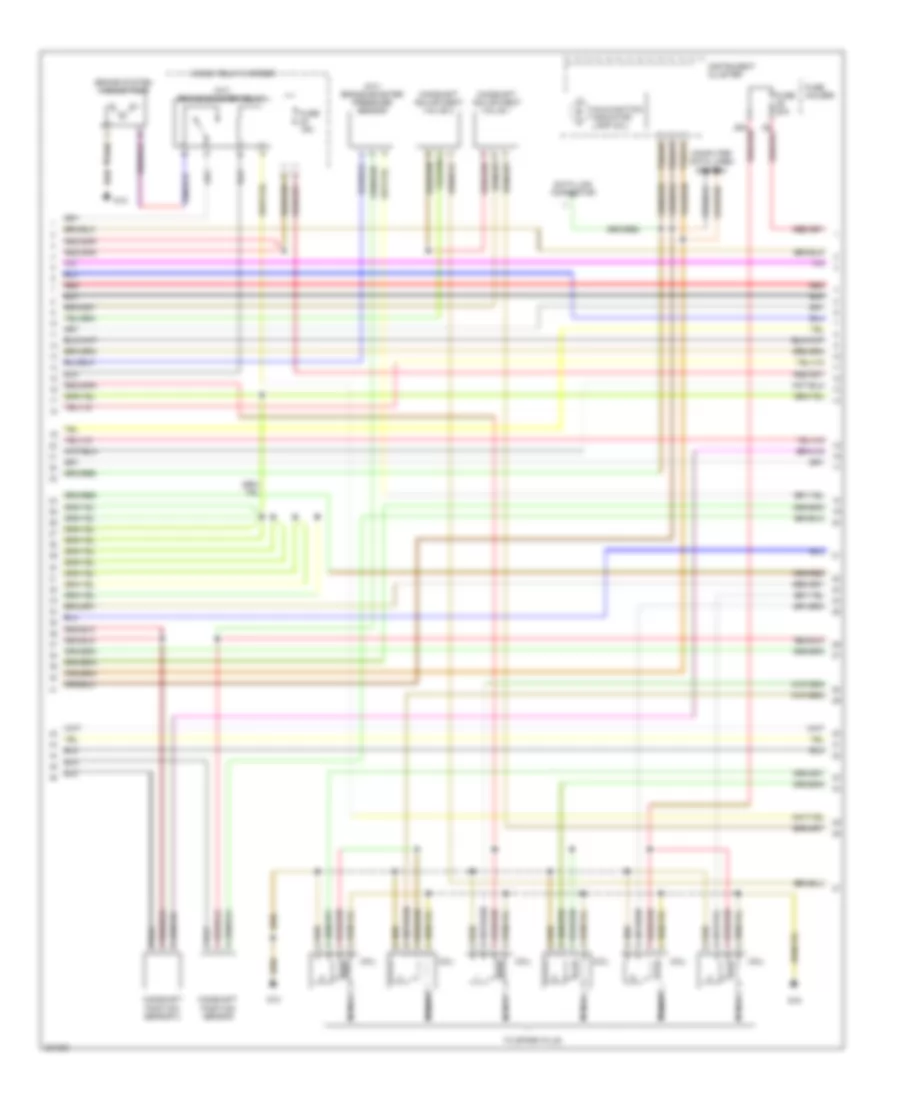
3.0L, Engine Performance Wiring Diagram (2 of 4) for Audi A4 2005
List of elements for 3.0L, Engine Performance Wiring Diagram (2 of 4) for Audi A4 2005:
- After-run coolant pump
- Camshaft position sensor 2
- Camshaft position sensor 4
- Coolant circulation pump relay
- Engine coolant temperature (ect) sensor
- Engine speed (rpm) sensor
- Evaporative emission (evap) canister purge regulator valve
- Fuse 15a
- Fuse holder
- G12
- Hot at all times
- Intake manifold change-over valve
- Knock sensor (ks) 1
- Knock sensor (ks) 2
- Leak detection pump (ldp)
- Nca
- Red
- Secondary air injection (air) solenoid valve
3.0L, Engine Performance Wiring Diagram (3 of 4) for Audi A4 2005
List of elements for 3.0L, Engine Performance Wiring Diagram (3 of 4) for Audi A4 2005:
- (a/t) brake booster pressure sensor
- (a/t) brake booster relay
- (mil)
- Brake system vacuum pump
- Camshaft adjustment valve 1
- Camshaft adjustment valve 2
- Camshaft position sensor
- Camshaft position sensor 3
- Coil
- Computer data lines system
- Data link connector
- E-box relay carrier
- Fuse 15a
- Fuse 20a
- Fuse holder
- G12
- G18
- Instrument cluster
- Malfunction indicator lamp
- Nca
- Red
- T32a/12
- T32a/13
- T32a/23
- To spark plug
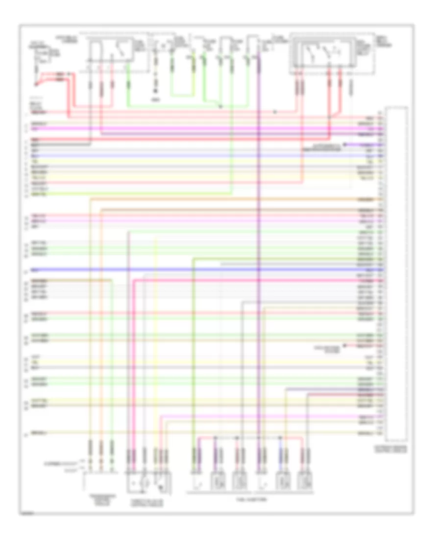
3.0L, Engine Performance Wiring Diagram (4 of 4) for Audi A4 2005
List of elements for 3.0L, Engine Performance Wiring Diagram (4 of 4) for Audi A4 2005:
- (5 speed) w/o cvt
- 9-pin relay carrier
- Cooling fans system
- E-box relay carrier
- Fuel injectors
- Fuel pump motor
- Fuel pump relay
- Fuse 150a
- Fuse 15a
- Fuse 20a
- Fuse holder
- G663
- Hot at all times
- Main fuse
- Motronic engine control module
- Red
- Relay plate
- Throttle valve control module
- Transmission control module
- W/ cvt