ENGINE PERFORMANCE
2.0L TURBO
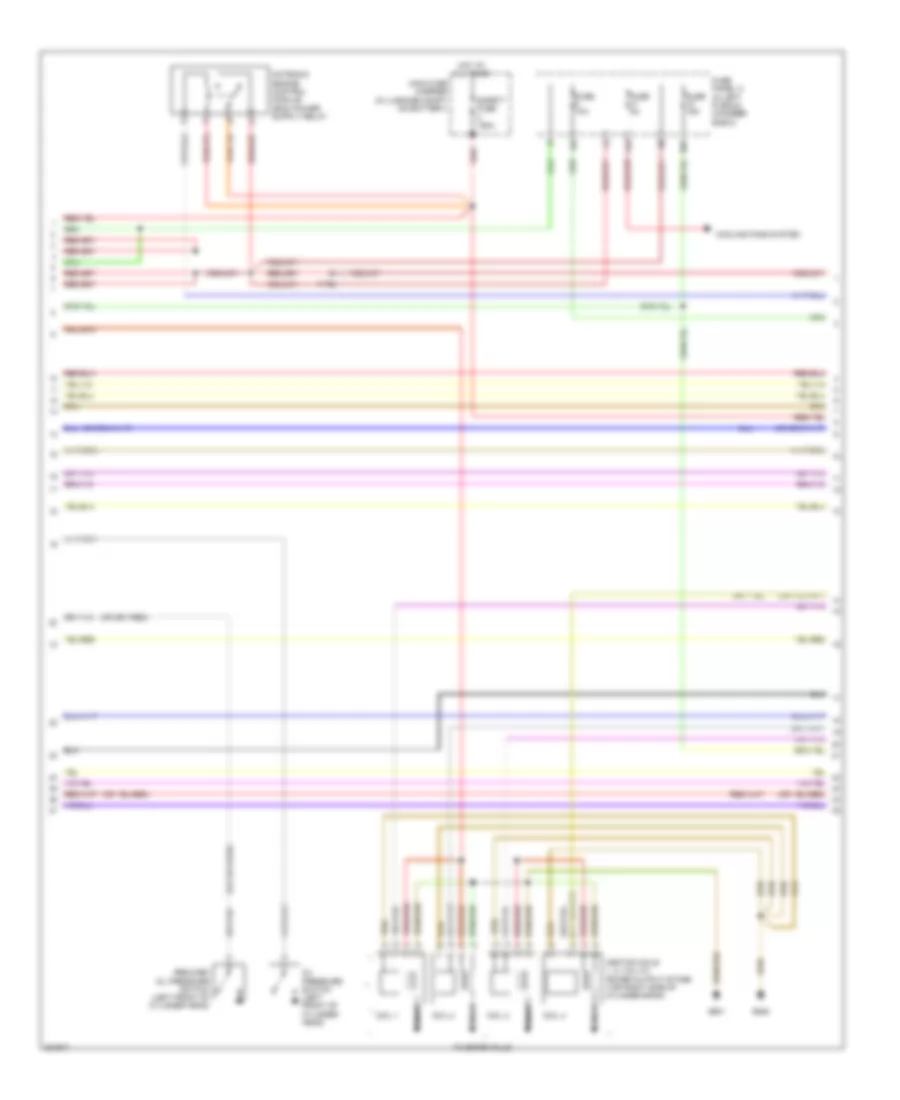
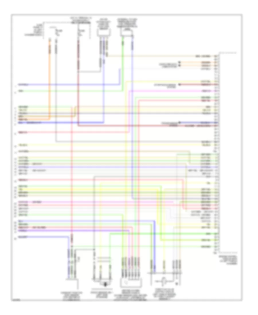
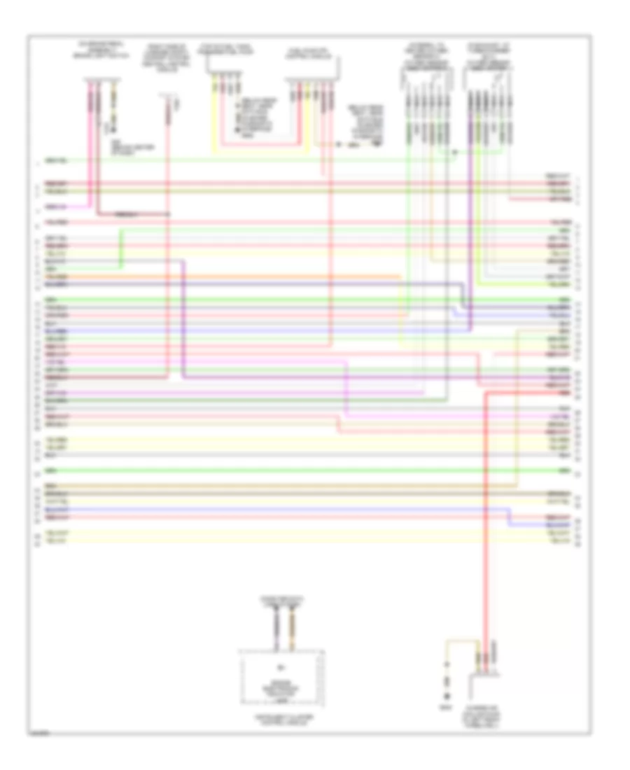
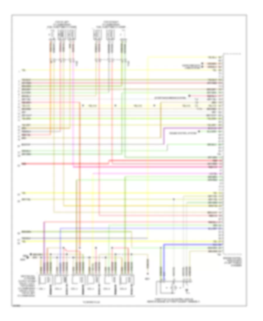
2.0L Turbo, Engine Performance Wiring Diagram (1 of 6) for Audi A6 2.0T 2012

List of elements for 2.0L Turbo, Engine Performance Wiring Diagram (1 of 6) for Audi A6 2.0T 2012:
- (right rear of luggage compt) comfort system central control module
- 14a
- Accelerator pedal position sensor & accelerator pedal position sensor 2 (top of accelerator pedal assembly)
- Cooling fans system
- Engine control module (ecm) (in left plenum chamber)
- Fuse 15a
- Fuse 20a
- Fuse 5a
- Fuse panel a (in left plenum chamber e-box)
- G645
- Heater for oxygen sensor 1 after catalytic converter & oxygen sensor after three way catalytic converter (in exhaust, downstream of 3-way catalytic converter)
- Nca
- Oil level thermal sensor (bottom of engine oil pan)
- Starting/ charging system
- Steering column electronic systems control module (top of steering column)
- System
- T16e
- T17a
- T17b
- T17h
- T17i
- T17o
- T32g
- T94
- Transmissions
- Transmissions system
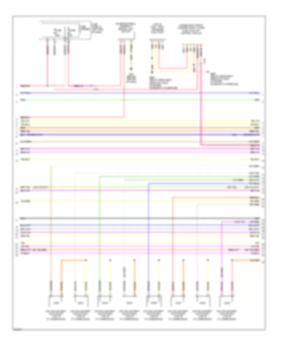
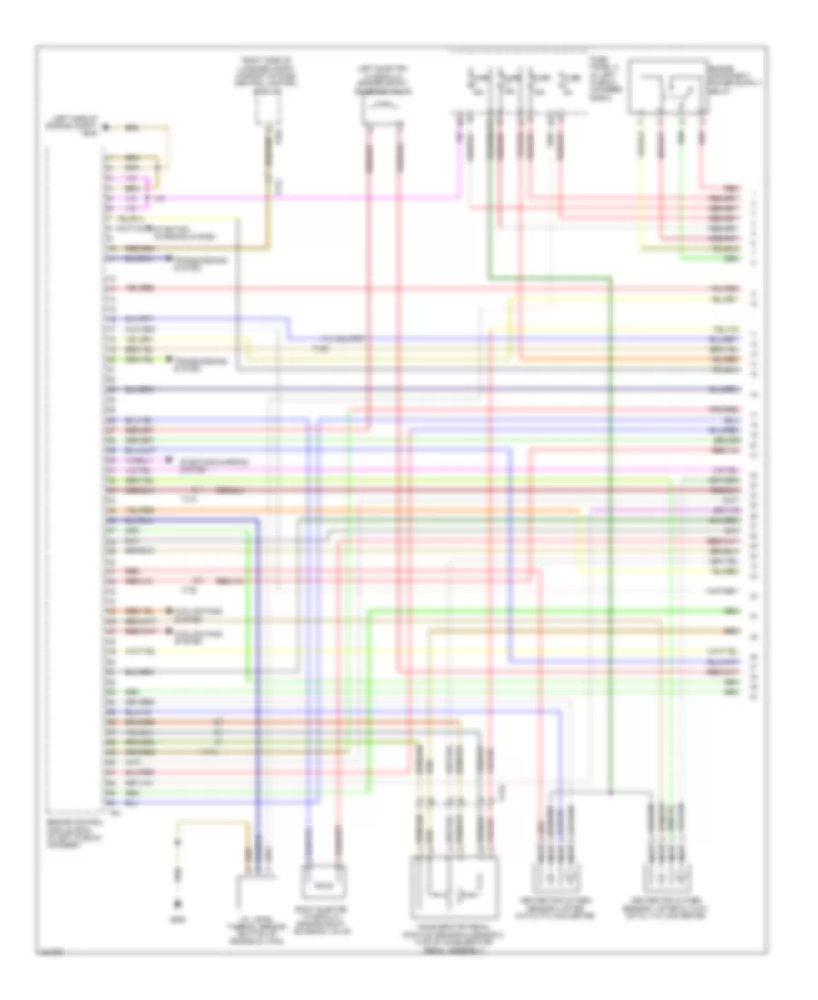
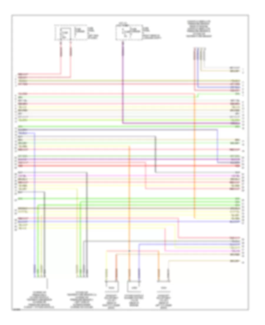
2.0L Turbo, Engine Performance Wiring Diagram (2 of 6) for Audi A6 2.0T 2012
List of elements for 2.0L Turbo, Engine Performance Wiring Diagram (2 of 6) for Audi A6 2.0T 2012:
- 10a
- 11a
- Coil 1
- Coil 2
- Coil 3
- Coil 4
- Cooling fans system
- Fuse 10a
- Fuse 15a
- Fuse 5a
- Fuse panel a (in left plenum chamber e-box)
- G601
- G645
- Hot at all times
- Ignition coils 1, 2, 3 & 4 w/ power output stage (top right side of cylinder bank)
- Main fuse carrier (in luggage compt on battery)
- Nca
- Oil pressure switch (left front of cylinder head)
- Red
- Reduced oil pressure switch (left front of cylinder head)
- Safety fuse 150a
- T17b
- To spark plug
2.0L Turbo, Engine Performance Wiring Diagram (3 of 6) for Audi A6 2.0T 2012
List of elements for 2.0L Turbo, Engine Performance Wiring Diagram (3 of 6) for Audi A6 2.0T 2012:
- (on brake pedal assembly) brake lamp switch
- (or red)
- (top of fuel tank) transfer fuel pump
- (under right front luggage compt floor) fuel pump (fp) control module
- Cam adjustment actuator 1 (top of cylinder bank)
- Cam adjustment actuator 2 (top of cylinder bank)
- Cam adjustment actuator 3 (top of cylinder bank)
- Cam adjustment actuator 4 (top of cylinder bank)
- Cam adjustment actuator 5 (top of cylinder bank)
- Cam adjustment actuator 6 (top of cylinder bank)
- Cam adjustment actuator 7 (top of cylinder bank)
- Cam adjustment actuator 8 (top of cylinder bank)
- Fuse 25a
- Fuse 5a
- Fuse carrier
- Fuse panel b (left end of dash)
- G45 (behind center of dash)
- G688 (below rear seat, near data bus on board diagnostic interface)
- Red
- T17b
- T17i
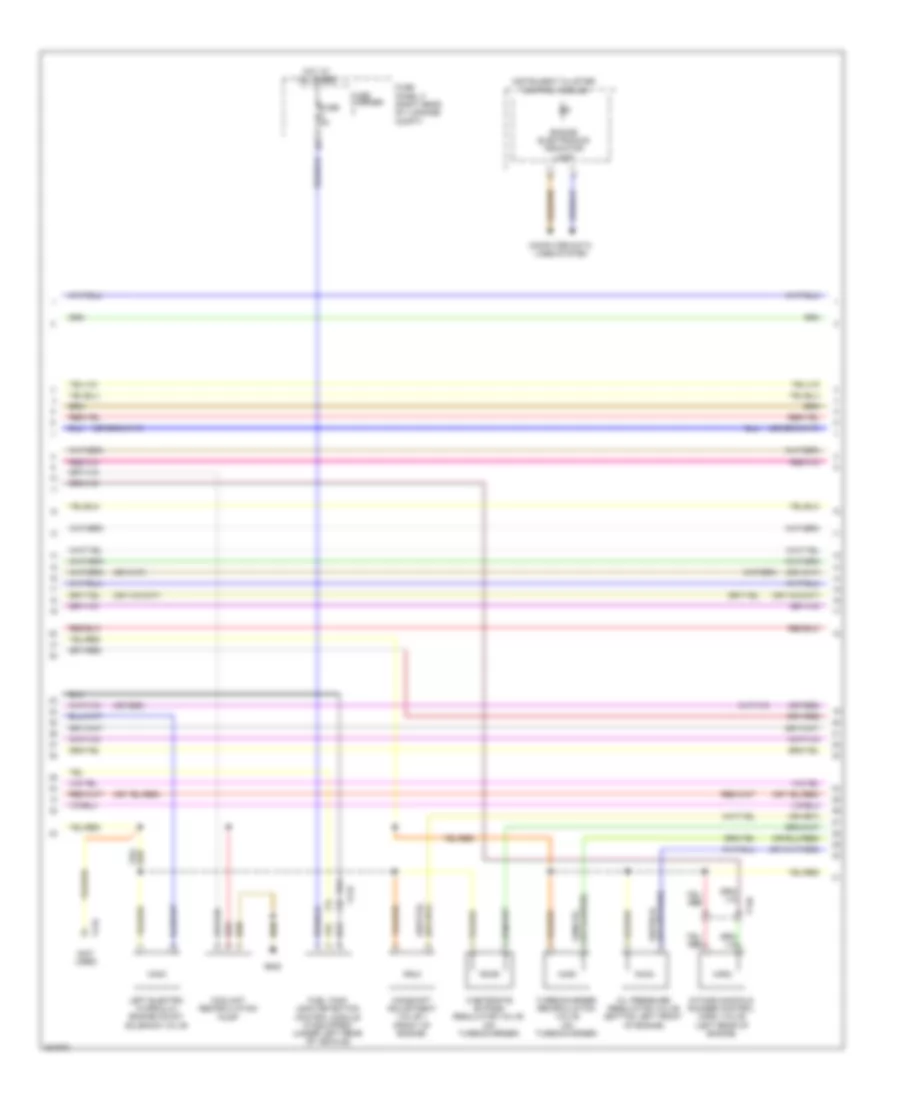
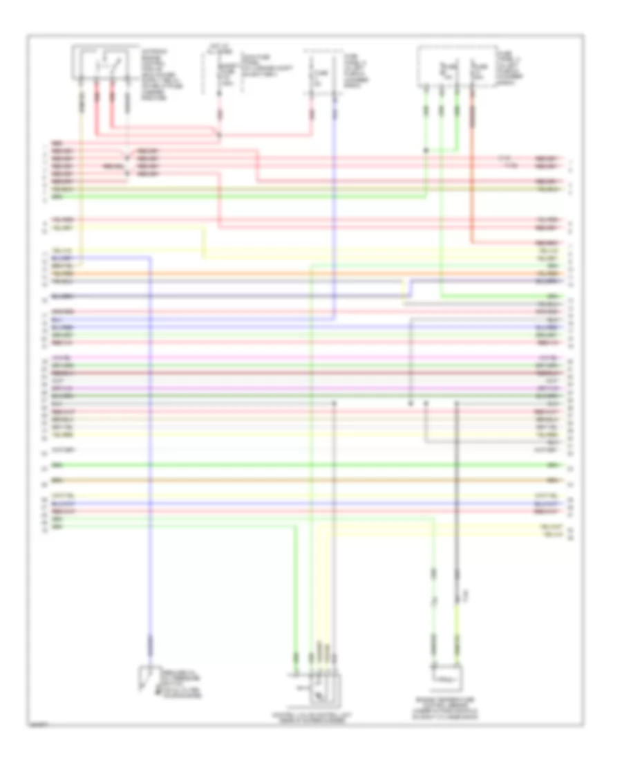
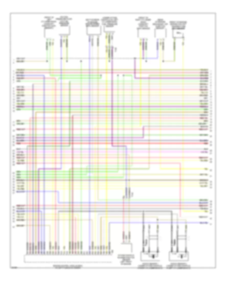
2.0L Turbo, Engine Performance Wiring Diagram (4 of 6) for Audi A6 2.0T 2012
List of elements for 2.0L Turbo, Engine Performance Wiring Diagram (4 of 6) for Audi A6 2.0T 2012:
- (not used)
- (or red)
- Camshaft adjustment valve 1 (front of engine)
- Computer data lines system
- Coolant recirculation pump
- Engine electronics indicator lamp
- Fuel tank leak detection control module (if equipped) (under left rear of vehicle)
- Fuse 5a
- Fuse carrier
- Fuse panel f (right rear of luggage compt)
- G645
- Hot at all times
- Instrument cluster control module
- Intake manifold runner control (imrc) valve (left rear of engine)
- Left electro hydraulic engine mount solenoid valve
- Oil pressure regulation valve (bottom left front of engine)
- Red
- T14b
- T17b
- Turbocharger recirculation valve (on turbocharger)
- Wastegate bypass regulator valve (on turbocharger)
2.0L Turbo, Engine Performance Wiring Diagram (5 of 6) for Audi A6 2.0T 2012
List of elements for 2.0L Turbo, Engine Performance Wiring Diagram (5 of 6) for Audi A6 2.0T 2012:
- (left front of engine compt) charge air pressure sensor
- (left front of engine) fuel pressure sensor
- (left front of engine) intake manifold runner position sensor
- (on intake manifold) intake air temperature (iat) sensor
- (or red)
- (top left side of engine)
- (top of cylinder bank) fuel injector cylinders 1, 2, 3 & 4
- Engine control module (ecm) (in left plenum chamber)
- Engine coolant temperature (ect) sensor
- Engine speed (rpm) sensor (bottom rear of engine)
- Evaporative emission (evap) canister purge regulator valve 1 (right rear of engine)
- T14b
- T60
- T8s
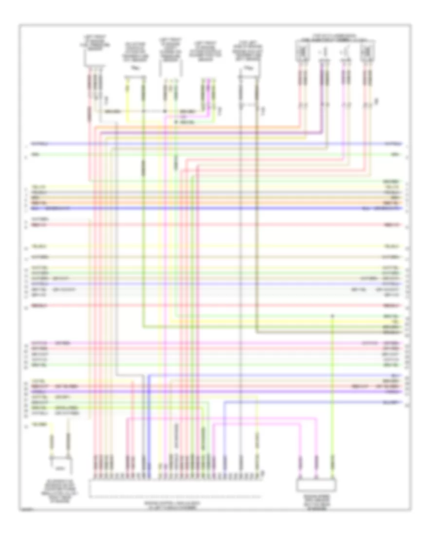
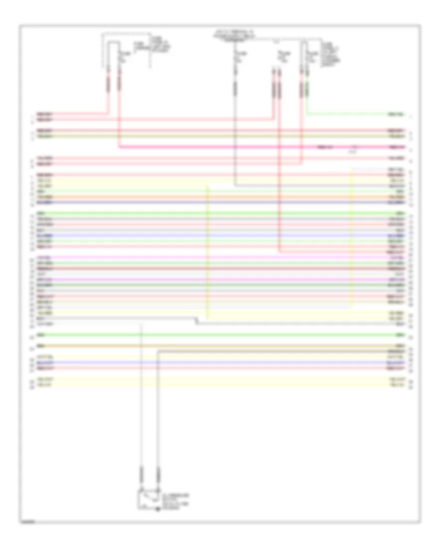
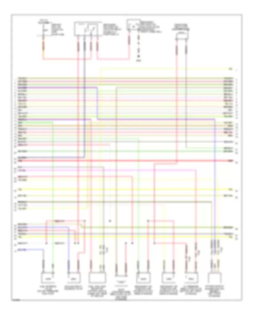
2.0L Turbo, Engine Performance Wiring Diagram (6 of 6) for Audi A6 2.0T 2012
List of elements for 2.0L Turbo, Engine Performance Wiring Diagram (6 of 6) for Audi A6 2.0T 2012:
- (integral to high pressure pump) fuel pressure regulator valve
- (on air intake duct) mass air flow (maf) sensor
- (or red)
- Camshaft position (cmp) sensor (top center of cylinder bank)
- Computer data lines system
- Engine control module (ecm) (in left plenum chamber)
- Fuse 5a
- Fuse panel a (in left plenum chamber e-box)
- Heated oxygen sensor (ho2s) & oxygen sensor (o2s) heater (in exhaust, upstream of 3-way catalytic converter)
- Knock sensor (ks) 1 (left side of engine)
- Nca
- Starting/charging system
- T14b
- T60
- T94
- Throttle valve control module (left side of engine, on throttle body assembly)
- Transmissions system
3.0L SC
3.0L SC, Engine Performance Wiring Diagram (1 of 8) for Audi A6 2.0T 2012
List of elements for 3.0L SC, Engine Performance Wiring Diagram (1 of 8) for Audi A6 2.0T 2012:
- (left side of engine compt) g645
- (right side of luggage compt) comfort system central control module
- 17a
- Accelerator pedal position sensor & sensor 2 (top of accelerator pedal assembly)
- Cooling fans system
- Engine control module (ecm) (in left plenum chamber)
- Fuse 15a
- Fuse 5a
- Fuse panel a (in left plenum chamber e-box)
- G645
- Heater for oxygen sensor 1 after & 3 way catalytic converter
- Heater for oxygen sensor 2 after catalytic converter
- Left electro hydraulic engine mount solenoid valve
- Nca
- Oil level thermal sensor (bottom of engine oil pan)
- Red
- Right electro hydraulic engine mount solenoid valve
- Starting/ charging system
- Starting/charging system
- T14b
- T17a
- T17b
- T17h
- T32g
- T94
- Transmissions system
3.0L SC, Engine Performance Wiring Diagram (2 of 8) for Audi A6 2.0T 2012
List of elements for 3.0L SC, Engine Performance Wiring Diagram (2 of 8) for Audi A6 2.0T 2012:
- 14a
- Control valve control unit (rear of supercharger)
- Engine temperature control sensor (under intake manifold, on right cylinder bank)
- Fuse 10a
- Fuse 20a
- Fuse 5a
- Fuse panel a (in left plenum chamber e-box)
- Hot at all times
- Main fuse panel (in luggage compt on battery)
- Red
- Reduced oil oil pressure switch (on oil filter housing base)
- Safety fuse 150a
- T14a
- T17b
3.0L SC, Engine Performance Wiring Diagram (3 of 8) for Audi A6 2.0T 2012
List of elements for 3.0L SC, Engine Performance Wiring Diagram (3 of 8) for Audi A6 2.0T 2012:
- 10a
- 16a
- Fuse 15a
- Fuse 5a
- Fuse carrier
- Fuse panel a (in left plenum chamber e-box)
- Fuse panel b (left end of dash)
- Oil pressure switch (on oil filter housing)
- T17i
3.0L SC, Engine Performance Wiring Diagram (4 of 8) for Audi A6 2.0T 2012
List of elements for 3.0L SC, Engine Performance Wiring Diagram (4 of 8) for Audi A6 2.0T 2012:
- (below rear seat, near data bus on board diagnostic interface) g688
- (in exhaust, at turbocharger exit) oxygen sensor (o2s) heater
- (integral to heated oxygen sensor 2) oxygen sensor (o2s) heater 2
- (on brake pedal assembly) brake light switch
- (right side of luggage compt) comfort system central control module
- (top of fuel tank) transfer fuel pump
- Charge air cooling pump (in left front wheelwell)
- Computer data lines system
- Engine electronics indicator lamp
- Fuel pump (fp) control module
- G45 (behind center of dash)
- G645
- Instrument cluster control module
- Nca
- Red
- T17o
- T32g
3.0L SC, Engine Performance Wiring Diagram (5 of 8) for Audi A6 2.0T 2012
List of elements for 3.0L SC, Engine Performance Wiring Diagram (5 of 8) for Audi A6 2.0T 2012:
- (manifold absolute pressure sensor: rear of engine) manifold absolute pressure sensor & intake air temperature sensor
- Camshaft adjustment valve 1 (rear of right cylinder bank)
- Camshaft adjustment valve 2 (rear of left cylinder bank)
- Charge air pressure & intake manifold temperature sensor (charge air pressure sensor: in bank 1 intake manifold)
- Fuse 25a
- Fuse 5a
- Fuse carrier
- Fuse panel b (left end of dash)
- Fuse panel f (right rear of luggage compt)
- Hot at all times
- Intake air temperature sensor 2 & charge air pressure sensor 2 (left side of supercharger charge air cooler)
- Intake manifold runner control valve (rear of engine)
- Red
3.0L SC, Engine Performance Wiring Diagram (6 of 8) for Audi A6 2.0T 2012
List of elements for 3.0L SC, Engine Performance Wiring Diagram (6 of 8) for Audi A6 2.0T 2012:
- (bottom rear of engine) engine speed (rpm) sensor
- (front of engine) engine coolant temperature (ect) sensor
- (front of left cylinder bank) camshaft position (cmp) sensor 2
- (front of right cylinder bank) camshaft position (cmp) sensor
- (on high pressure pump) low fuel pressure sensor
- (rear of engine) secondary air injection sensor 1
- (under intake manifold on left cylinder bank) fuel pressure sensor
- Engine control module (ecm) (in left plenum chamber)
- Intake manifold runner position sensor (left front of engine)
- Knock sensor 1 (under intake manifold, in right cylinder bank 2)
- Knock sensor 2 (under intake manifold, in left cylinder bank 2)
- Nca
- Red
- T14a
- T14b
- T60
3.0L SC, Engine Performance Wiring Diagram (7 of 8) for Audi A6 2.0T 2012
List of elements for 3.0L SC, Engine Performance Wiring Diagram (7 of 8) for Audi A6 2.0T 2012:
- 50a
- Cooling circuit solenoid valve
- Crankcase ventilation shut-off valve
- Evap canister purge regulator valve 1 (left side of engine)
- Fuel metering valve (on high pressure fuel pump)
- Fuel tank leak detection control module (under left rear of vehicle)
- G645
- Hot at all times
- Intake manifold runner position sensor 2 (left front of engine)
- Oil pressure regulation valve (bottom left front of engine)
- Red
- Second- ary air injection (air) pump fuse
- Secondary air injection (air) pump motor (inside right front wheelwell)
- Secondary air injection (air) pump relay (on relay & fuse panel a)
- Secondary air injection (air) solenoid valve (rear of engine)
- Secondary air injection (air) solenoid valve 2 (rear of engine)
- T14a
- T14b
- T17b
3.0L SC, Engine Performance Wiring Diagram (8 of 8) for Audi A6 2.0T 2012
List of elements for 3.0L SC, Engine Performance Wiring Diagram (8 of 8) for Audi A6 2.0T 2012:
- (top of left cylinder bank) fuel injectors cylinder
- (top of right cylinder bank) fuel injectors cylinder
- Coil 1
- Coil 2
- Coil 3
- Coil 4
- Coil 5
- Coil 6
- Computer data lines system
- Cruise control system
- Engine control module (ecm) (in left plenum chamber)
- G600
- G601
- G645
- Ignition coil w/ power output stage (coils 1, 2 & 3 : top of right cylinder bank (coils 4, 5 & 6 : top of left cylinder bank)
- Nca
- Red
- Starting/charging system
- T14a
- T14b
- T17a
- T60
- T94
- Throttle valve control module (rear of engine, on throttle body assembly)
- To spark plug