INSTRUMENT CLUSTER
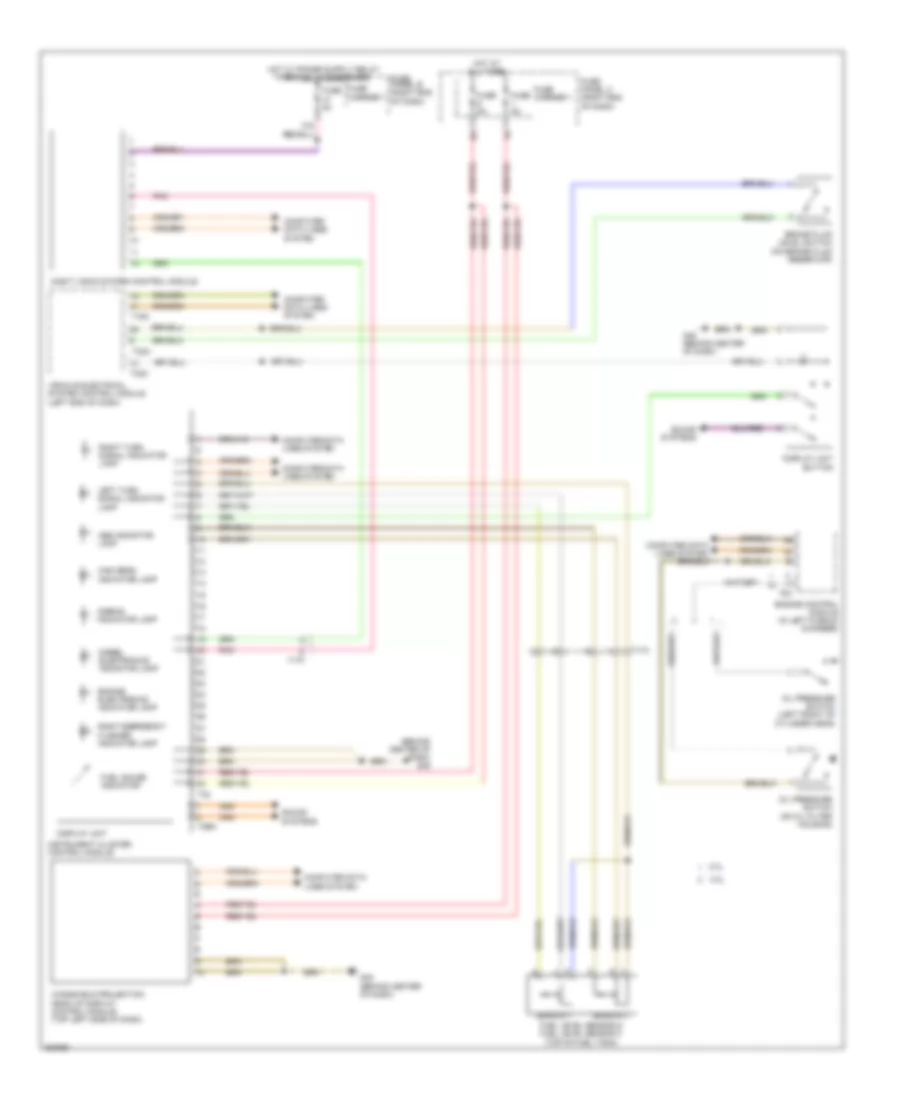
Instrument Cluster Wiring Diagram for Audi A6 2.0T 2012
List of elements for Instrument Cluster Wiring Diagram for Audi A6 2.0T 2012:
- (behind center of dash) g45
- 10a
- 2.0l
- 3.0l
- Abs indicator lamp
- Airbag indicator lamp
- Brake fluid level switch (on brake fluid reservoir)
- Computer data lines system
- Diesel electronics indicator lamp
- Display unit
- Display unit button
- Engine control module (in left plenum chamber)
- Engine electronics indicator lamp
- Fuel gauge indicator
- Fuel level sensor & fuel level sensor 2 (top of fuel tank)
- Fuse 5a
- Fuse carrier 1
- Fuse panel b (right end of dash)
- Fuse panel c (right end of dash)
- G45 (behind center of dash)
- High beam indicator lamp
- Hot at all times
- Instrument cluster control module
- Left turn signal indicator lamp
- Night vision system control module
- Oil pressure switch (left front of cylinder head)
- Oil pressure switch (on oil filter housing)
- Pnk
- Right emergency flasher indicator lamp
- Right turn signal indicator lamp
- Sensor 1
- Sensor 2
- Sound systems
- T16c
- T17f
- T17h
- T2bm
- T32
- T32a
- T32c
- T94
- Vehicle electrical system control module (left end of dash)
- Windshield projection head up display control module (top left side of dash)
 English