ENGINE PERFORMANCE
3.7L
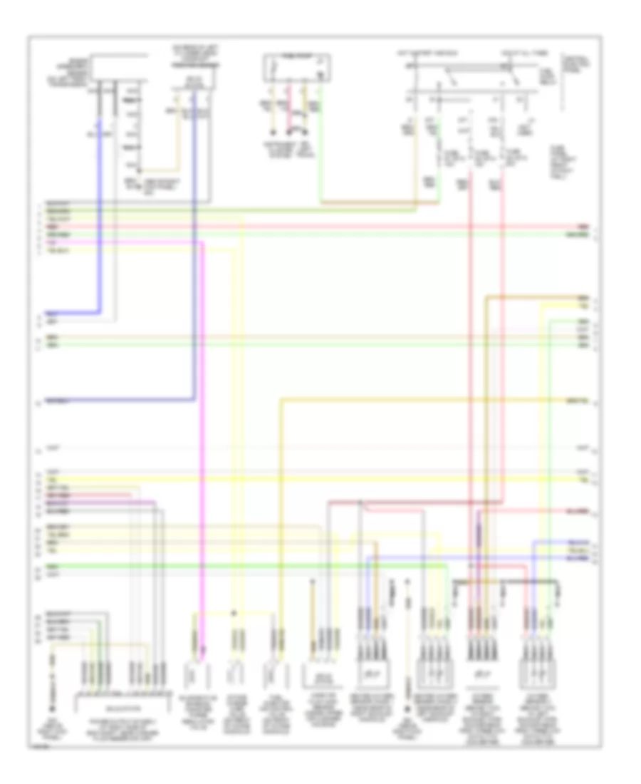
3.7L, Engine Performance Wiring Diagram (1 of 3) for Audi A8 1997

List of elements for 3.7L, Engine Performance Wiring Diagram (1 of 3) for Audi A8 1997:
- (on bottom of throttle body) intake air temperature sensor
- A10
- A11
- A12
- A13
- A14
- A15
- A16
- A17
- A18
- A19
- A20
- A21
- A22
- A23
- A24
- B10
- B11
- B12
- B13
- B14
- B15
- B16
- B17
- B18
- B19
- B20
- B21
- B22
- B23
- B24
- Battery
- Closed throttle position switch/ throttle position sensor
- Engine coolant temperature sensor
- Fuse s115 20a
- Fuse s116 15a
- Fuse s117 15a
- G43 (above right kick panel)
- G600 (on right cylinder head)
- G601 (on left cylinder head)
- Hot in start and run
- Ignition coil 1
- Ignition coil 2
- Ignition coil 3
- Ignition coil 4
- Ignition coil 5
- Ignition coil 6
- Ignition coil 7
- Ignition coil 8
- Motronic engine control module (in plenum chamber e-box)
- Nca
- Plenum chamber e-box relay & fuse panel (in plenum chamber e-box)
- Plug spark
- Power output stage 1 (at right side of eng compt, near washer fluid reservoir cap)
- Red
- Solid state
- Spark plug
- T4a
- Transmission control module (in plenum chamber e-box)
- Transmissions system
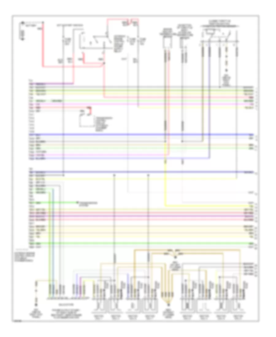
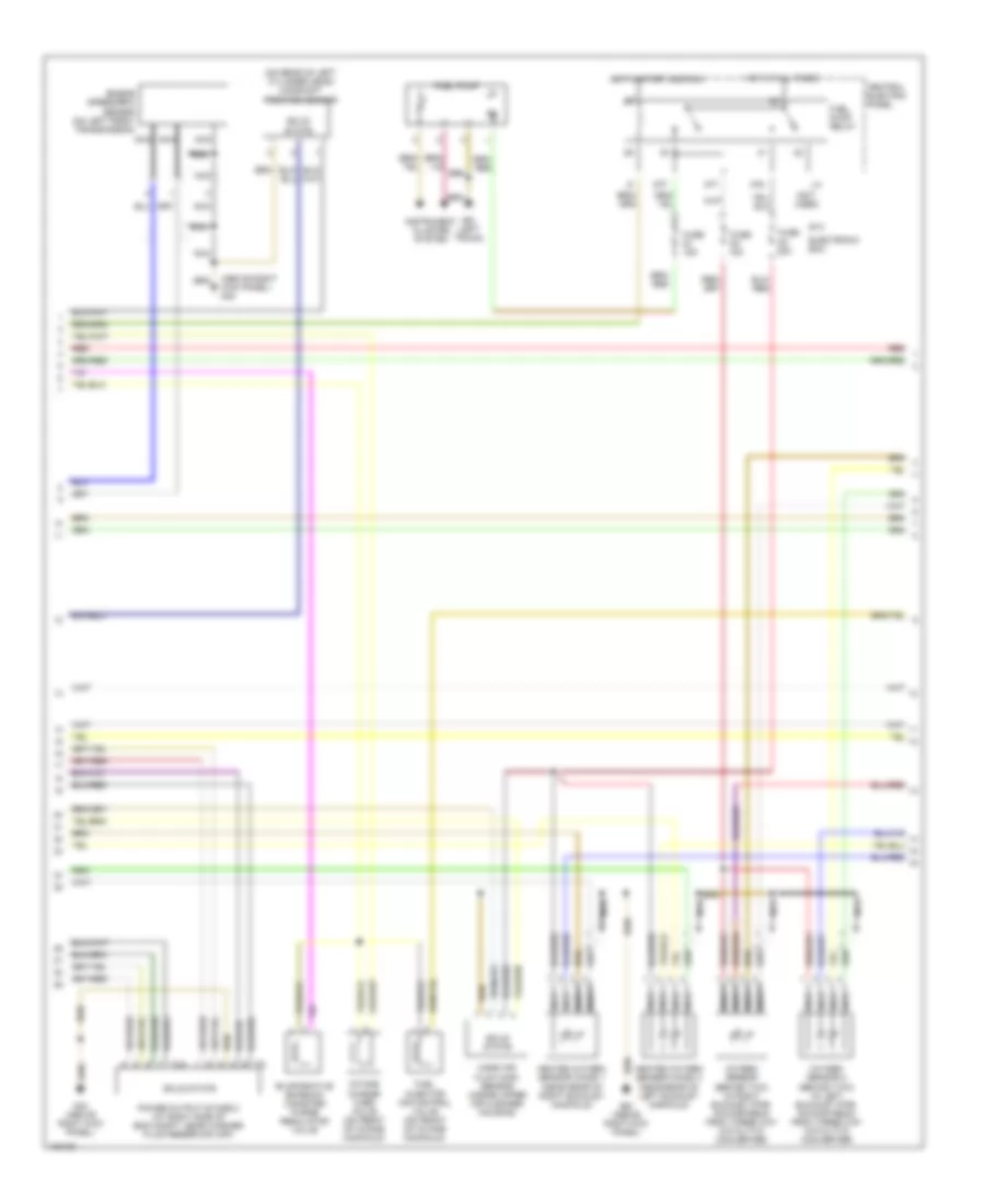
3.7L, Engine Performance Wiring Diagram (2 of 3) for Audi A8 1997
List of elements for 3.7L, Engine Performance Wiring Diagram (2 of 3) for Audi A8 1997:
- (above right kick panel) g43
- (not used)
- (on rear of left cylinder head) camshaft position sensor
- 87f
- 87a
- Central electric panel
- Dti
- Engine speed(rpm) sensor (on left front transmission)
- Evaporative emission canister purge regulator valve
- Fuel injector air control valve (on front of intake manifold)
- Fuel pump
- Fuel pump relay
- Fuse panel (at right front of foot- well)
- Fuse s1 (st4) 15a
- Fuse s3 (st4) 20a
- Fuse s4 (st4) 15a
- G43 (above right kick panel)
- G51 (left trunk)
- Heated oxygen sensor (ho2s) 1 (near rear of right exhaust manifold)
- Heated oxygen sensor (ho2s) 2 (near rear of left exhaust manifold)
- Hot at all times
- Hot in start and run
- Instrument cluster system
- Intake change over valve (on front of intake manifold)
- Mass air flow (maf) sensor (inside upper air cleaner housing)
- Nca
- Oxygen sensor (behind twc) (in right exhaust pipe, downstream from three way catalytic converter)
- Oxygen sensor 2 (behind twc) (in left exhaust pipe, downstream from three way catalytic converter)
- Power output stage 2 (at right side of eng compt, near washer fluid reservoir cap)
- Red
- Solid state
- T4a
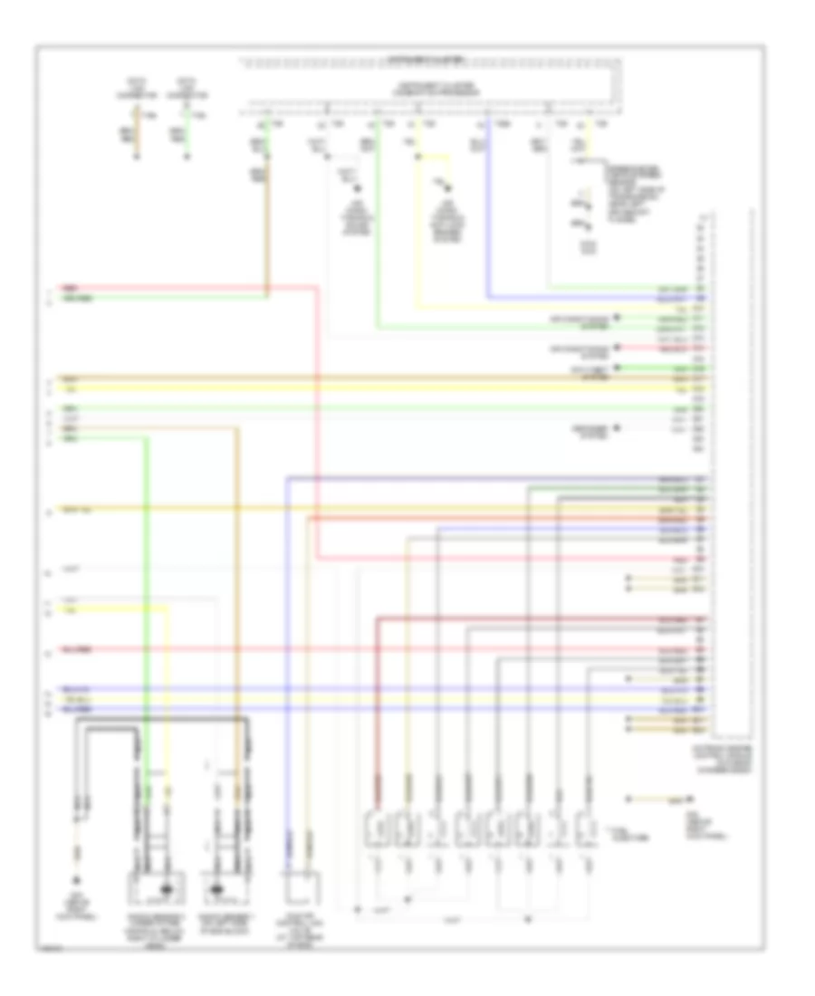
3.7L, Engine Performance Wiring Diagram (3 of 3) for Audi A8 1997
List of elements for 3.7L, Engine Performance Wiring Diagram (3 of 3) for Audi A8 1997:
- Air condi- tioning & anti-lock brakes system
- Air condi- tioning & sound system
- Air conditioning system
- Anti-theft system
- C1
- C10
- C11
- C12
- C13
- C14
- C15
- C16
- C17
- C18
- C19
- C20
- C21
- C22
- C23
- C24
- D10
- D11
- D12
- Data link connector
- Defogger system
- E10
- E11
- E12
- Fuel injectors
- G102 (n/a)
- G43 (above right kick panel)
- Idle air control (iac) valve (at top rear of eng)
- Instrument cluster
- Instrument cluster combination processor
- Knock sensor 1 (on left side of eng block)
- Knock sensor 2 (under intake manifold, below right cylinder head)
- Motronic engine control module (in plenum chamber e-box)
- Nca
- Red
- Speedometer vehicle speed sensor (on left side of transmission, near left driveshaft flange)
- T16a
- T16b
- T26
- T26a
4.2L
4.2L, Engine Performance Wiring Diagram (1 of 3) for Audi A8 1997
List of elements for 4.2L, Engine Performance Wiring Diagram (1 of 3) for Audi A8 1997:
- (on bottom of throttle body) intake air temperature sensor
- A10
- A11
- A12
- A13
- A14
- A15
- A16
- A17
- A18
- A19
- A20
- A21
- A22
- A23
- A24
- B10
- B11
- B12
- B13
- B14
- B15
- B16
- B17
- B18
- B19
- B20
- B21
- B22
- B23
- B24
- Battery
- Closed throttle position switch/ throttle position sensor
- Engine coolant temperature sensor
- Fuse s115 20a
- Fuse s116 15a
- Fuse s117 15a
- G43 (above right kick panel)
- G600 (on right cylinder head)
- G601 (on left cylinder head)
- Hot in start and run
- Ignition coil 1
- Ignition coil 2
- Ignition coil 3
- Ignition coil 4
- Ignition coil 5
- Ignition coil 6
- Ignition coil 7
- Ignition coil 8
- Motronic engine control module (in plenum chamber e-box)
- Nca
- Plug spark
- Power output stage 1 (at right side of eng compt, near washer fluid reservoir cap)
- Red
- Solid state
- Spark plug
- T4a
- Transmission control module (in plenum chamber e-box)
- Transmissions system
4.2L, Engine Performance Wiring Diagram (2 of 3) for Audi A8 1997
List of elements for 4.2L, Engine Performance Wiring Diagram (2 of 3) for Audi A8 1997:
- (above right kick panel) g43
- (not used)
- (on rear of left cylinder head) camshaft position sensor
- 87f
- 87a
- Central electric panel
- Dti
- Electronic box
- Engine speed(rpm) sensor (on left front transmission)
- Evaporative emission canister purge regulator valve
- Fuel injector air control valve (on front of intake manifold)
- Fuel pump
- Fuel pump relay
- Fuse s1 15a
- Fuse s3 20a
- Fuse s4 15a
- G43 (above right kick panel)
- G51 (left trunk)
- Heated oxygen sensor (ho2s) 1 (near rear of right exhaust manifold)
- Heated oxygen sensor (ho2s) 2 (near rear of left exhaust manifold)
- Hot at all times
- Hot in start and run
- Instrument cluster system
- Intake change over valve (on front of intake manifold)
- Mass air flow (maf) sensor (inside upper air cleaner housing)
- Nca
- Oxygen sensor (behind twc) (in right exhaust pipe, downstream from three way catalytic converter)
- Oxygen sensor 2 (behind twc) (in left exhaust pipe, downstream from three way catalytic converter)
- Power output stage 2 (at right side of eng compt, near washer fluid reservoir cap)
- Red
- Solid state
- St4
- T4a
4.2L, Engine Performance Wiring Diagram (3 of 3) for Audi A8 1997
List of elements for 4.2L, Engine Performance Wiring Diagram (3 of 3) for Audi A8 1997:
- Air condi- tioning & anti-lock brakes system
- Air condi- tioning & sound system
- Air conditioning system
- Anti-theft system
- C1
- C10
- C11
- C12
- C13
- C14
- C15
- C16
- C17
- C18
- C19
- C20
- C21
- C22
- C23
- C24
- D10
- D11
- D12
- Data link connector
- Defogger system
- E10
- E11
- E12
- Fuel injectors
- G102 (n/a)
- G43 (above right kick panel)
- Idle air control (iac) valve (at top rear of eng)
- Instrument cluster
- Instrument cluster combination processor
- Knock sensor 1 (on left side of eng block)
- Knock sensor 2 (under intake manifold, below right cylinder head)
- Motronic engine control module (in plenum chamber e-box)
- Nca
- Red
- Speedometer vehicle speed sensor (on left side of transmission, near left driveshaft flange)
- T16a
- T16b
- T26
- T26a