INSTRUMENT CLUSTER
Instrument Cluster Wiring Diagram (1 of 3) for Audi A8 1997

List of elements for Instrument Cluster Wiring Diagram (1 of 3) for Audi A8 1997:
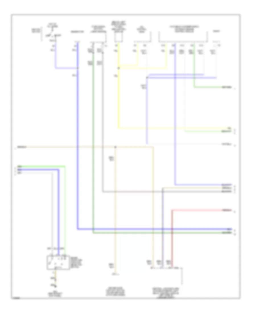
Instrument Cluster Wiring Diagram (2 of 3) for Audi A8 1997
List of elements for Instrument Cluster Wiring Diagram (2 of 3) for Audi A8 1997:
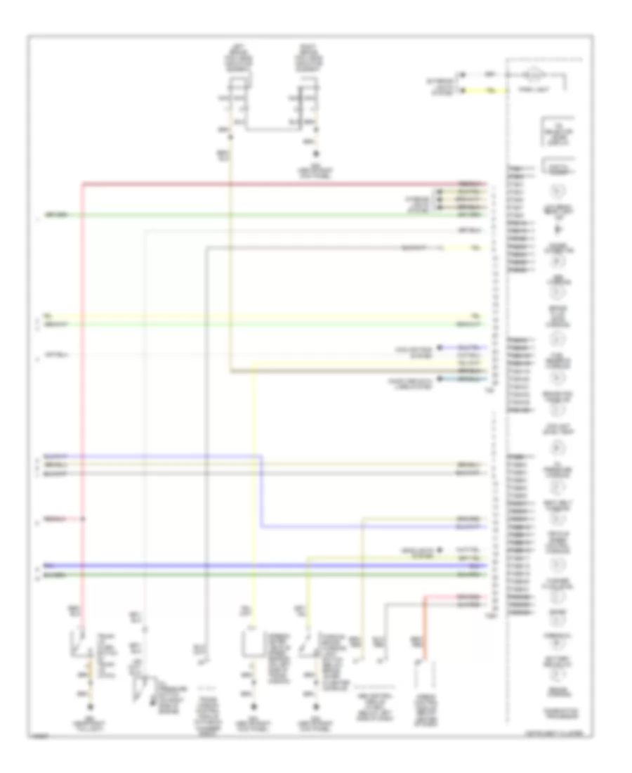
Instrument Cluster Wiring Diagram (3 of 3) for Audi A8 1997
List of elements for Instrument Cluster Wiring Diagram (3 of 3) for Audi A8 1997: