ENGINE PERFORMANCE
2.0L TURBO
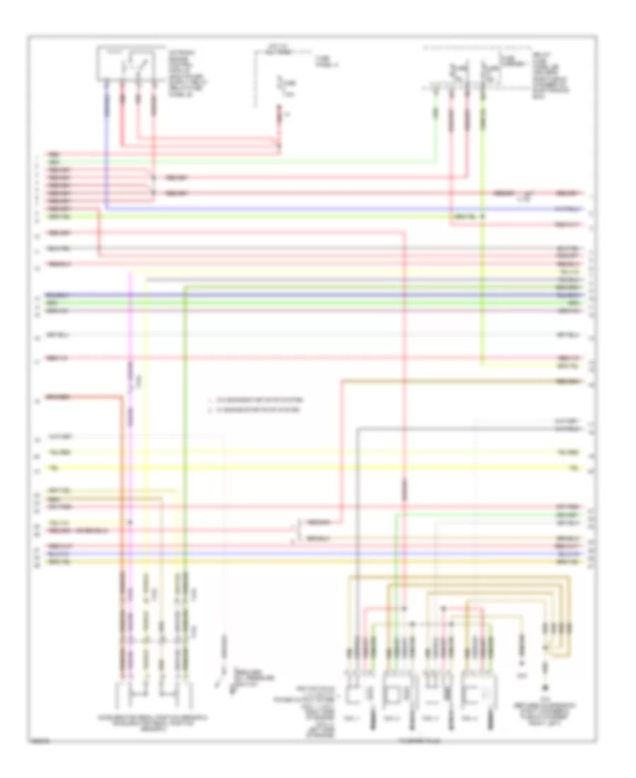
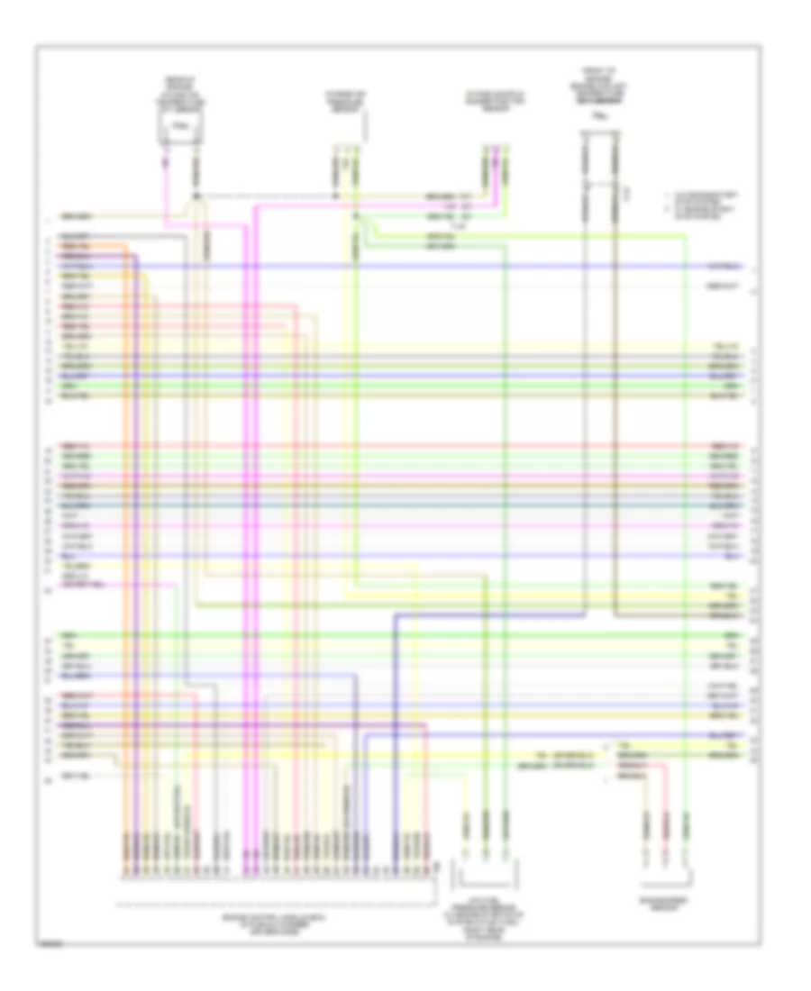
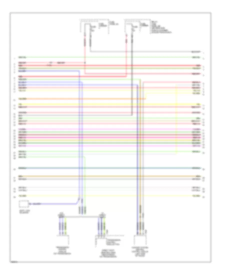
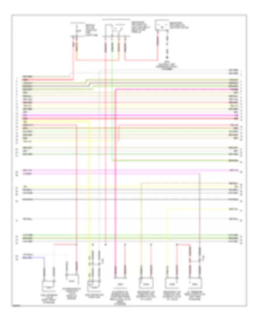
2.0L Turbo, Engine Performance Wiring Diagram (1 of 7) for Audi Q5 2.0T 2011

List of elements for 2.0L Turbo, Engine Performance Wiring Diagram (1 of 7) for Audi Q5 2.0T 2011:
- (between suspension strut chamber & plenum chamber front left) g12
- (left side of trunk) comfort system central control module
- Brake booster pressure sensor (w/ engine start/stop system)
- Cooling fans system
- Cruise control system
- Engine control module (ecm) (in plenum chamber driver's side)
- Fuse 15a
- Fuse 20a
- Fuse 5a
- Fuse carrier 1
- G12 (between suspension strut chamber & plenum chamber front left)
- Nca
- Oil level thermal sensor
- Oxygen sensor (o2s) behind 3-way catalytic converter (twc) (behind three way catalytic converter)
- Red
- Relay/fuse panel sb (driver's side plenum chamber on electronics box)
- Starting/ charging system
- Stop system
- System
- T17r
- T32d
- T94
- Transmission neutral position sensor (w/ engine start/stop system)
- Transmissions
- Vehicle positioning system interface control module
- W/ engine start/
- W/o engine start/
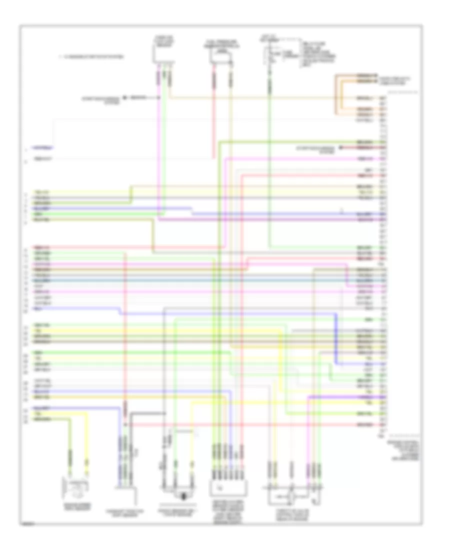
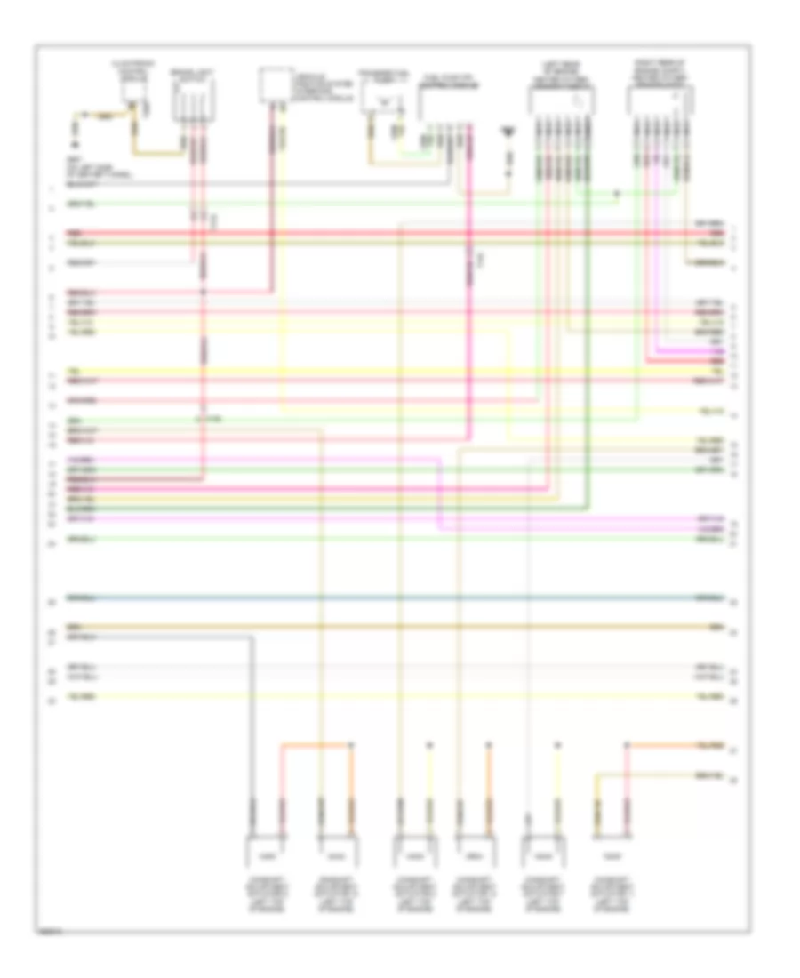
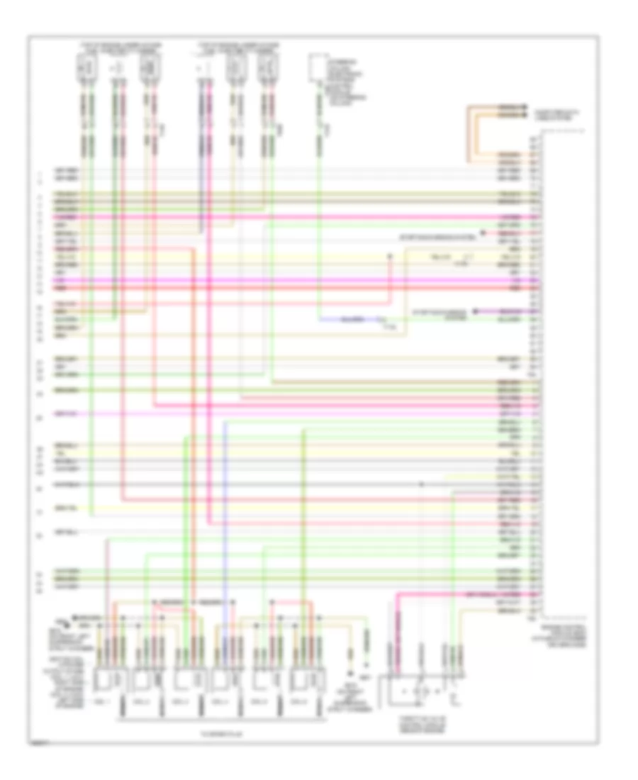
2.0L Turbo, Engine Performance Wiring Diagram (2 of 7) for Audi Q5 2.0T 2011
List of elements for 2.0L Turbo, Engine Performance Wiring Diagram (2 of 7) for Audi Q5 2.0T 2011:
- 10a
- Accelerator pedal position sensor & accelerator pedal position sensor 2
- Coil 1
- Coil 2
- Coil 3
- Coil 4
- Fuse 110a
- Fuse 15a
- Fuse carrier 1
- Fuse panel a
- G12 (between suspension strut chamber & plenum chamber front left)
- G15
- Hot at all times
- Ignition coils 1, 2, 3 & 4 w/ power output stage (coil 1, 2 & 3: right side of engine) (coil 4: left side of engine)
- Nca
- Red
- Reduced oil pressure switch
- Relay/ fuse panel sb (driver's side plenum chamber on electronics box)
- T17e
- T17q
- T17r
- To spark plug
- W/ engine start/stop system
- W/o engine start/stop system
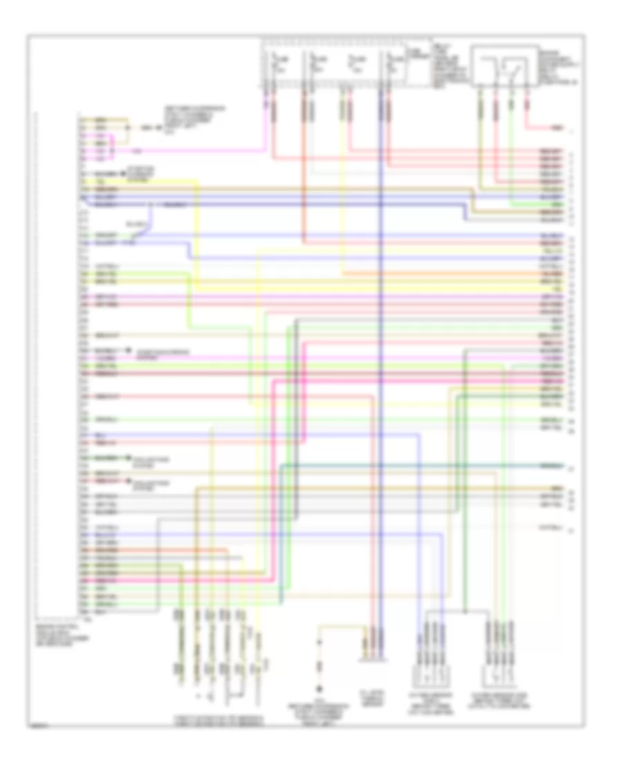
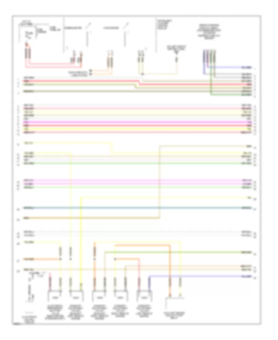
2.0L Turbo, Engine Performance Wiring Diagram (3 of 7) for Audi Q5 2.0T 2011
List of elements for 2.0L Turbo, Engine Performance Wiring Diagram (3 of 7) for Audi Q5 2.0T 2011:
- (left top of engine)
- (top of right cylinder head)
- Auxiliary engine coolant pump relay
- Brake light switch
- Camshaft adjustment actuator 1
- Camshaft adjustment actuator 2
- Camshaft adjustment actuator 3
- Camshaft adjustment actuator 4
- Camshaft adjustment actuator 5
- Camshaft adjustment actuator 6
- Camshaft adjustment actuator 7
- Camshaft adjustment actuator 8
- Fuel level sensor & transfer pump (fp)
- Fuel pump (fp) control module
- Fuse 25a
- Fuse carrier
- Fuse panel sc
- G663
- T17e
- T17q
- W/ engine start/stop system
- W/o engine start/stop system
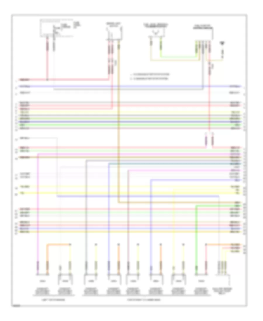
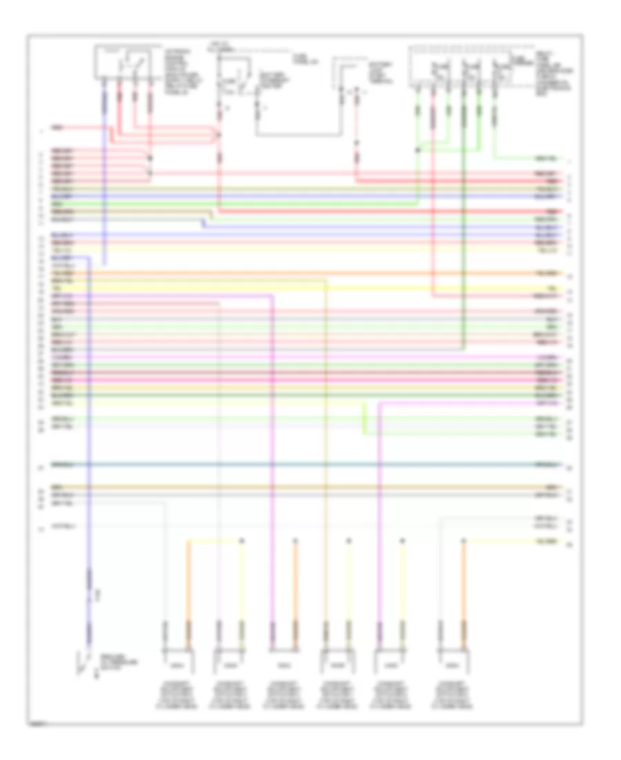
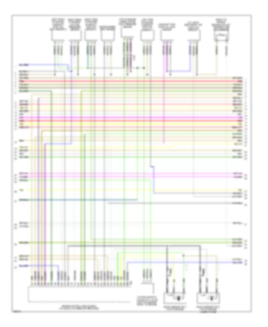
2.0L Turbo, Engine Performance Wiring Diagram (4 of 7) for Audi Q5 2.0T 2011
List of elements for 2.0L Turbo, Engine Performance Wiring Diagram (4 of 7) for Audi Q5 2.0T 2011:
- (left side of trunk) comfort system central control module
- (not used)
- (on transmission) transmission control module
- Camshaft adjustment valve 1 (right rear of engine)
- Climatronic control module
- Climatronic refrigerant shut-off valve (rear center of engine compt)
- Coil start injector (w/ start/stop system)
- Computer data lines system
- G687 (on left side of center tunnel)
- Instrument cluster control module
- Leak detection pump (ldp) (w/o start/stop system)
- Left electro hydraulic engine mount solenoid valve (a/t)
- Right electro hydraulic engine mount solenoid valve (w/ start/stop system)
- T17b
- T17q
- T20e
- T32d
- W/ engine start/stop system
- W/o engine start/stop system
2.0L Turbo, Engine Performance Wiring Diagram (5 of 7) for Audi Q5 2.0T 2011
List of elements for 2.0L Turbo, Engine Performance Wiring Diagram (5 of 7) for Audi Q5 2.0T 2011:
- (top of engine under intake) fuel injectors 1, 2, 3 & 4
- (top of engine under intake) fuel pressure sensor
- Evap canister purge regulator valve (rear of engine)
- Fuel quality sensor (w/ engine start/stop system & flex fuel)
- Intake manifold runner control (imrc) valve
- Oil pressure regulation valve (left side of engine)
- T14f
- T17t
- T8w
- Turbocharger recirculation valve
- W/ engine start/stop system
- W/o engine start/stop system
- Wastegate bypass regulator valve
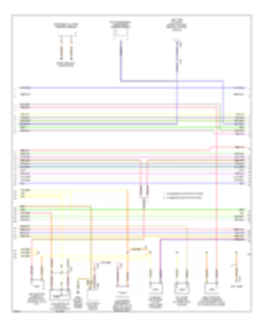
2.0L Turbo, Engine Performance Wiring Diagram (6 of 7) for Audi Q5 2.0T 2011
List of elements for 2.0L Turbo, Engine Performance Wiring Diagram (6 of 7) for Audi Q5 2.0T 2011:
- (front of engine) engine coolant temperature (ect) sensor
- (rear of engine) intake air temperature (iat) sensor
- Charge air pressure sensor
- Engine control module (ecm) (in plenum chamber driver's side)
- Engine speed sensor
- Intake manifold runner position sensor
- Low fuel pressure sensor (w/ engine start/stop system & flex fuel) (right rear of engine)
- Stop system w/ engine start/ stop system
- T14f
- T60
- W/o engine start/
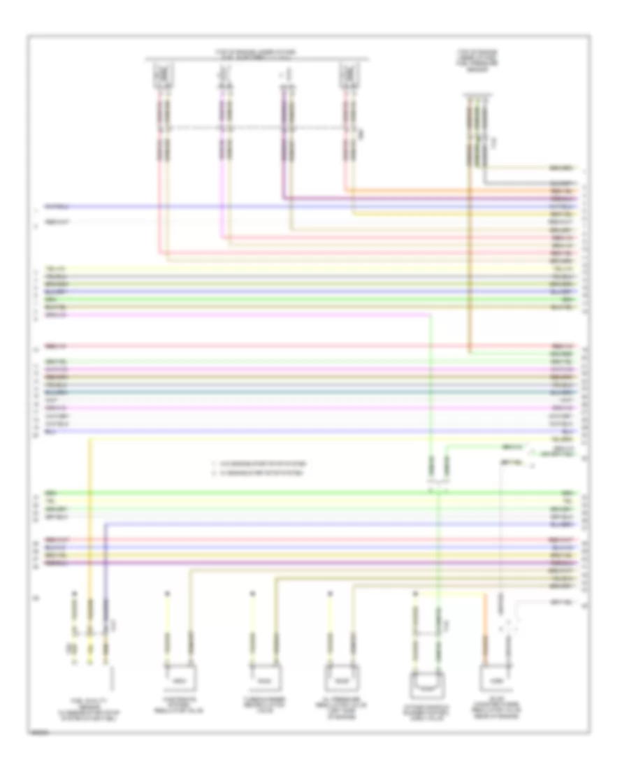
2.0L Turbo, Engine Performance Wiring Diagram (7 of 7) for Audi Q5 2.0T 2011
List of elements for 2.0L Turbo, Engine Performance Wiring Diagram (7 of 7) for Audi Q5 2.0T 2011:
- Camshaft position (cmp) sensor
- Computer data lines system
- Engine control module (ecm) (in plenum chamber driver's side)
- Engine speed (rpm) sensor
- Fuel pressure regulator valve
- Fuse 5a
- Fuse carrier
- Heated oxygen sensor (ho2s) & oxygen sensor (o2s) heater (right rear of engine compt)
- Hot at all times
- Knock sensor (ks) 1 (top of engine)
- Mass air flow (maf) sensor
- Nca
- Relay/fuse panel sb (driver's side plenum chamber on electronics box)
- Starting/charging system
- T14f
- T60
- T94
- Throttle valve control module (rear of engine)
- W/ engine start/stop system
3.2L
3.2L, Engine Performance Wiring Diagram (1 of 8) for Audi Q5 2.0T 2011
List of elements for 3.2L, Engine Performance Wiring Diagram (1 of 8) for Audi Q5 2.0T 2011:
- (between suspension strut chamber & plenum chamber front left) g12
- Cooling fans system
- Engine control module (ecm) (in plenum chamber driver's side)
- Fuse 15a
- Fuse 20a
- Fuse 5a
- Fuse carrier
- G12 (between suspension strut chamber & plenum chamber front left)
- Nca
- Oil level thermal sensor
- Oxygen sensor (o2s) (behind three way catalytic converter)
- Oxygen sensor (o2s) 2 (behind three way converter)
- Red
- Relay/ fuse panel sb (driver's side plenum chamber on electronics box)
- Starting/ charging system
- Starting/charging system
- T17e
- T17q
- T17r
- T94
- Throttle position (tp) sensor & throttle position (tp) sensor 2
3.2L, Engine Performance Wiring Diagram (2 of 8) for Audi Q5 2.0T 2011
List of elements for 3.2L, Engine Performance Wiring Diagram (2 of 8) for Audi Q5 2.0T 2011:
- 10a
- Battery interrupt igniter
- Battery jump start terminal
- Camshaft adjustment actuator 1 (top of right cylinder head)
- Camshaft adjustment actuator 2 (top of right cylinder head)
- Camshaft adjustment actuator 3 (top of right cylinder head)
- Camshaft adjustment actuator 4 (top of right cylinder head)
- Camshaft adjustment actuator 5 (top of right cylinder head)
- Camshaft adjustment actuator 6 (top of right cylinder head)
- Fuse 110a
- Fuse 15a
- Fuse carrier
- Fuse panel sa
- Hot at all times
- Red
- Reduced oil pressure switch
- Relay/ fuse panel sb (driver's side plenum chamber on electronics box)
- T14e
3.2L, Engine Performance Wiring Diagram (3 of 8) for Audi Q5 2.0T 2011
List of elements for 3.2L, Engine Performance Wiring Diagram (3 of 8) for Audi Q5 2.0T 2011:
- Comfort system central control module (left side of trunk)
- Direct shift gear box (dsg) mechatronic (on transmission)
- Fuse 25a
- Fuse 5a
- Fuse carrier
- Fuse panel sc
- Red
- Relay/ fuse panel sb (driver's side plenum chamber on electronics box)
- Shift lock solenoid
- T16r
- T17q
- T17r
- T32d
- Transmission control module (on transmission)
- Transmission control module (tcm)
- W/ direct shift
- W/o direct shift
3.2L, Engine Performance Wiring Diagram (4 of 8) for Audi Q5 2.0T 2011
List of elements for 3.2L, Engine Performance Wiring Diagram (4 of 8) for Audi Q5 2.0T 2011:
- (left rear of engine) heated oxygen sensor (ho2s) 2
- (right rear of engine compt) heated oxygen sensor (ho2s)
- Brake light switch
- Camshaft adjustment actuator 10 (left top of engine)
- Camshaft adjustment actuator 11 (left top of engine)
- Camshaft adjustment actuator 12 (left top of engine)
- Camshaft adjustment actuator 7 (left top of engine)
- Camshaft adjustment actuator 8 (left top of engine)
- Camshaft adjustment actuator 9 (left top of engine)
- Climatronic control module
- Fuel pump (fp) control module
- G663
- G687 (on left side of center tunnel)
- Nca
- Red
- T17e
- T17q
- T17r
- T20e
- Transfer fuel pump
- Venicile positing system interface control module
3.2L, Engine Performance Wiring Diagram (5 of 8) for Audi Q5 2.0T 2011
List of elements for 3.2L, Engine Performance Wiring Diagram (5 of 8) for Audi Q5 2.0T 2011:
- (on left side of center tunel) g687
- (rear of engine) manifold absol- ute pressure (map)/ intake air temperature (iat) sensor
- Auxiliary engine coolant pump relay
- Camshaft adjustment valve 1 (exhaust) (right rear of engine)
- Camshaft adjustment valve 1 (right rear of engine)
- Camshaft adjustment valve 2 (exhaust) (left rear of engine)
- Camshaft adjustment valve 2 (left rear of engine)
- Climatronic control module
- Climatronic refrigerant shut-off valve (rear center of engine compt)
- Computer data lines system
- Fuse 10a
- Fuse carrier
- Fuse panel sd
- Hot at all times
- Instrument cluster control module
- Red
- Speedometer
- T17b
- T17q
- T20e
- Tachometer
3.2L, Engine Performance Wiring Diagram (6 of 8) for Audi Q5 2.0T 2011
List of elements for 3.2L, Engine Performance Wiring Diagram (6 of 8) for Audi Q5 2.0T 2011:
- (front of engine) engine coolant temperature (ect) sensor
- (left front of engine) camshaft position (cmp) sensor 2
- (left side of engine) camshaft position sensor 4
- (right rear of engine) low fuel pressure sensor
- (right side of engine) camshaft position sensor 3
- (top of engine under intake) fuel pressure sensor
- (w/ ulev2) secondary air injection sensor 1
- Camshaft posi- position (cmp) sensor
- Engine control module (ecm) (in plenum chamber driver's side)
- Engine speed (rpm) sensor
- Intake manifold tuning (imt) valve position sensor (front of engine)
- Knock sensor (ks) 1 (top of engine)
- Knock sensor (ks) 2 (top of engine under intake)
- Nca
- Red
- T14e
- T60
3.2L, Engine Performance Wiring Diagram (7 of 8) for Audi Q5 2.0T 2011
List of elements for 3.2L, Engine Performance Wiring Diagram (7 of 8) for Audi Q5 2.0T 2011:
- 30a
- Evaporative emission (evap) canister purge regulator valve (rear of engine)
- Fuel metering valve (right front of engine)
- G615 (on front left suspension strut chamber)
- Intake manifold tuning (imt) valve (front of engine)
- Leak detection pump (ldp)
- Oil pressure regulator valve (left side of engine)
- Red
- Second- ary air injection (air) pump fuse
- Secondary air injection (air) pump motor
- Secondary air injection (air) pump relay (relay/fuse panel b)
- Secondary air injection (air) solenoid valve (w/ ulev2)
- Secondary air injection (air) solenoid valve 2 (w/ ulev2)
- T14e
- T17q
3.2L, Engine Performance Wiring Diagram (8 of 8) for Audi Q5 2.0T 2011
List of elements for 3.2L, Engine Performance Wiring Diagram (8 of 8) for Audi Q5 2.0T 2011:
- (top of engine under intake) fuel injector cylinders
- Coil 1
- Coil 2
- Coil 3
- Coil 4
- Coil 5
- Coil 6
- Computer data lines system
- Engine control module (ecm) (in plenum chamber driver's side)
- G600
- G601
- G615 (on front left suspension strut chamber)
- Ignition coil w/power output stage (coil 1, 2 & 3: right side of engine) (coil 4, 5 & 6: left side of engine)
- Module (on steering column)
- Nca
- Red
- Starting/charging system
- Steering column electronic systems control t16f
- T14e
- T17b
- T17q
- T17r
- T60
- T6ad
- T94
- Throttle valve control module (rear of engine)
- To spark plug